

Emerson Freitas Jaguaribe , Adriano Sitônio Rumão , Fernanda de Souza Silva , Vicente de Vasconcelos Claudino Filho , Wendell Venício de Araújo Galdino & Francisco Everton Tavares de Luna
I. INTRODUCTION
A t least five facts underlie the understanding that biomass is the most important source of energy in the world, [1], [2], [3], [4]. [5] [6], and they are based on the following: 1. It is a renewable fuel, [7], [8];
It is neutral as regards the emission of greenhouse gases, [1], [9], [10];
It is capable of replacing conventional fossil fuels, [1] to [6];
It is abundant, [2], [3] and [6]; Its resources are found almost everywhere [11-12]. There are several biomass conversions, with different characteristics and results [13]. The most efficient way to make the internal chemical energy of biomass available is through the production of gas either by biochemical (fermentation) or thermo chemical (pyrolysis) processes, the latter requiring more external energy, but with faster practical results [14].
a) Biomass Gasifier and Gasification Process
As well known, depending on their characteristics (method of heating, gasification agent, pressurization, transport processes, etc.) gasifiers may be classified into different types, [13], [15]. When the distinction is based on the way biomass and the gas flow move, biomass gasifiers are conceived of as fixed bed (updraft, or downdraft), fluidized bed, entrained flow, etc. The fixed bed gasifier with a fuel hopper top (also known as moving bed) is the most common [16]. It has been preferred to the closed top gasifier, such as the Imbert gasifier (throated or closed top gasifier). The reasons are: the fuel is easily fed; quick access to the instrumentation for needed control measurements; air and biomass pass uniformly downward through the four zones (drying, pyrolysis, combustion and reduction), avoiding excessive deviation from the local high average temperature; less trouble with channeling or bridging events; the top zone may be easily and conveniently adjusted [15].
Gasification agents may be air, steam, oxygen or . The fixed bed gasifier, also considered very suitable for internal combustion engines, by reason of producing low tar content, [16], [17], is appropriate for small to medium scale thermal applications [18]. Depending on the gasification agent flow direction, a gasifier may be designated as countercurrent, co-current, cross flow, etc. Generally speaking, the co-current gasifier is used in small scale power generation and the air coming from nozzles set around the reactor zone, as well as from the top (about 60%) moves downward in the same direction as the produced gas (the poor gas). It is observed that in co-current gasifiers air input rates regulate the fuel consumption rates [19]. On the other hand, the reactor is simple to construct and generates a poor gas with low tar in its composition [20], [21].
Particle size is one of the most recurrent independent variables appearing in almost all pyrolysis or devolatilization models through a non-dimensional number . However, most pyrolysis studies do not make reference to any non-dimensional number, see e.g. , , , . Thus, considerations of the influence of the fuel dimension on the gasifier functionality, mostly come from phenomenological results, allowing to enunciate some statements such as: 1. Fine grained, or fluffy particles may produce gas flow difficulties inside the gasifier body reactor [27], with considerable pressure drops over the reduction zone;
Disproportional large sizes can give rise to bridging and channeling problems [4];
Biomass particle size, as well as, its moisture content are important factors affecting the combustion and heat recovery, especially if combustion is incomplete [22], [24] and [28];
The flame propagation speed, i.e., the rate of progress of the apparent flame zone, is dependent on the particle size, as well as on the air supply rate, and the calorific value of the solid fuel, Shin et al. [29];
A reduction in the fuel particle size leads to a significant improvement in the gasification parameters, Hernandez et al. [30].
Not only should size, but also particle density be considered when the goal is to improve gasification results. In fact, it is easy to notice that density often figures in the chemical kinetics and transport phenomena correlations, where those fundamentals, as mentioned above, are necessary to help to describe the pyrolysis models , , and . Huff demonstrated the importance of size, shape, density, moisture, and wall furnace temperature in the burning time of single pieces in fireboxes.
In reading the technical literature, we understand that the influence of the biomass particle size on the gasification process has been extensively, theoretically or experimentally, studied. However, it should be noted that most of the studies, experimental, or theoretical (models), take into account just isolated particles, [21], [22], [28], [29], [30], [31], [32], [33].
It was only around 1920 that poor (producer) gas was used to fuel engines, Shrinivasa et al. [34]. In fact, the petroleum shortage during World War II led to widespread applications of gas generation in the transportation industries of Western Europe, La Fontaine et al. [35]. As mentioned by FAO [27], spark ignition engines can be run on poor gas (producer gas) alone, and Diesel engines can be converted into full poor gas after being submitted to some modifications, or run in a dual mode. The use of poor gas on internal engines, tar and particulate contents have since been proved too great a hurdle. This fact motivated the Indian Institute of Science in Bangalore, see Dasappa et al. [36], to develop biomass gasifiers capable of cleaning and cooling the poor gas, to be used in dual fuel mode (diesel/poor gas). In fact, the majority of poor gas application in engines uses the dual mode, e.g. Shrinivasa et al. [34], Dasappa et al. [36], Sridhar et al. [37], Dasappa et al. [38], Kalina [39] and Ghosh et al. [40]. Less frequent is the utilization of IC engines fueled just on poor gas: Raman et al. [41], for example, used an engine designed to run on natural gas to operate on producer gas, and Gitano [42] modified a gasoline two-stroke genset for operating on syngas (producer gas) from a biomass gasifier.
The present work discusses the global efficiency of a system formed by a co-current, downdraft fixed bed biomass gasifier, coupled to a genset, and an Otto Cycle engine to generate electricity. The biomass gasifier fuels the genset with a hundred percent poor gas. The influence of some biomass properties, such as size, density and moisture content on this overall process is analyzed.
II. PRODUCING THE POOR GAS
a) Dynamics of the gasifier reactor
At least four stages are necessary for biomass gasification: drying, pyrolysis, combustion and reduction. Being dependent on heat transfer properties, the drying process, aside from the moisture and the ash content, may also depend, as already reported, on some fuel (biomass) physical parameters, such as size, heat diffusivity, heat capacity, heat transfer coefficient, and thermal conductivity. At the beginning of the process, there is evaporation inside the fuel, production of condensable fractions with loss of water, which happens at temperatures above C. On the other hand, volatiles are released at temperatures close to C. At the same time, steam escapes from the particles, causing fuel and pores shrinkage, as well as the ending of the drying process. As the temperature increases, it is easy to detect the presence of and CO, chiefly when cellulose is heated at C, Hill [43]. Generally speaking, pyrolysis or release of volatiles have been considered as the first stage in gas production from biomass, Di Blasi [6]. The use of thermo gravimetric analysis shows that all volatiles are released up to C, the lignin at this temperature being completely thermally degraded. Tar, the product of destructive distillation, and ash in the reactor occur at temperatures higher than C, Yoshikawa [44]. It is observed that the pyrolysis product will react at high temperatures, 700 to C for existent gases, chiefly for external , in the combustion zone, where secondary reactions generally occur. During this process conversion of residual char is detected, presenting much slower reaction than the oxidation process, Basu [45], determining the overall gasification efficiency. Finally, as particles move into the reduction zone, they become smaller due to the consumption of the char by surface reactions. It is also in this zone that the char particles act as reducing agents for the remaining gaseous compounds, De Santanu [46], forming the poor gas, basically a mixture of , CO and .
b) The Experiment
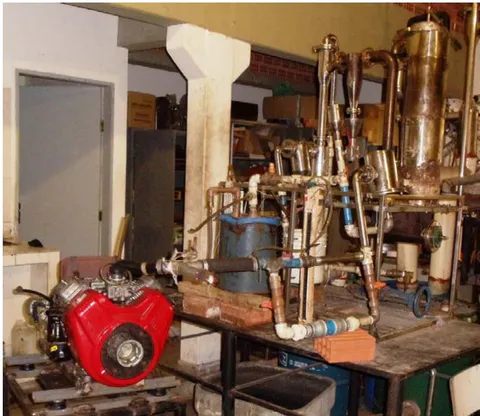
As mentioned earlier, this work deals with a system formed by a downdraft, co-current, open-top 8.5 thermal kW biomass gasifier and a genset, see Figure 1, to produce electricity. The gasifier reactor 0.90 m long with internal and external diameters of 0.16 m, and 0.18 m, respectively, has the annular space filled with vermiculite. The genset parts are: an original gasoline VANGUARD V-Twin, 2 cylinders, 18-hp Otto cycle, adapted to run on poor gas. and a generator from Toyama (model TG2500MX), single phase, 220 V and 60 Hz.
A resistive charge simulator with eight electric resistances is capable of testing electric powers up to 2.4 kW. An electric energy analyzer from HIOKI is used to evaluate the frequencies, current, and the electric power produced by the genset.
Gases emissions (CO, HC, and ) and the lambda factor are evaluated by means of an Alphatest vehicular gas analyzer.
A thermocouple, K type, is used to evaluate the exhausted gases temperature.
c) The Biomass
Four different types of waste wood material, brought from the university campus dump and cut into uneven cubic pieces, originated the four different biomass samples, characterized by their four different edges (The first, third and fourth samples were from the species Tabebuia heptaphylla, and the second from Ceasalpinia echinata). On average, the edge and the cubic volume of the samples (1 to 4) were respectively, 13 mm (2; 197 mm ), 16 mm (4,096 mm ), 20 mm (8,000 mm ) and 27 mm (19,683 mm ). For each one of the tests, the gasifier ran with just one kind of sample.
The moisture content of each one of the four samples was determined experimentally in triplicate.
For the analysis of the biomass sample results, a proximate analysis, using the ASTM E-1131 Standard Test Method for Compositional Analysis by Thermo gravimetry was also conducted in triplicate. For these tests, 30 mg of each sample with an average diameter of 100 mm, was brought to a 100 mL.min gas flow ( and synthetic air), using different temperature levels.
d) The low heating value of the poor gas
As mentioned by Reed et al. [17], the gas heating value of raw producer gas containing significant condensable volatiles (tars) is difficult to measure, since the measurements are made at room temperature after the tar has been condensed. Generally speaking, in the technical literature, we find different average values. For Reed et al. [17], the lower heating value, LHV, of the producer gas, situates between 5–7 MJ.Nm ; Barrio et al. [47] 4.85 MJ.Nm ; Albertazzi et al. [48], 5 MJ.Nm ;
Kaupp et al. [49] between 4 and 6 MJ.Nm . There are, however, two publications, Yoshikawa [44] and Garcia [50], that show the plot of the LHV of the poor gas given in function of the percentage of carbon monoxide by volume of poor gas. Based on this set of scattered points, Rumão [51], using a curve fitting process, determined Eq. (1), which produced a Pearson's correlation coefficient equal to 0.9379, with a standard deviation of MJ.Nm . The correlation, see Eq. (1), gives the LHV of the poor gas in terms of the percentage of CO by volume of poor gas, as MJ.Nm . (Typically, in the poor gas composition, for hydrogen and carbon monoxide, it is 19± 1% H and 19± 1% CO. Therefore, in Eq. (1) the effect of H was replaced by the one of CO by just altering its coefficients);
e) Efficiency of the system gasifier/genset
Equation (2) was used to evaluate the efficiency of the system (gasifier/genset)
Where
is the generated electric power, W;
is the evaluated mass flow used to feed the gasifier, kg/s;
is the average biomass low calorific value, J/kg, which was determined experimentally in triplicate.
f) Determining the efficiency of the internal combustion engine coupled to the genset
Since the final efficiency of the system depends on the efficiency of its elements, a series of experiments was made to determine the efficiency of the internal combustion engine coupled to the genset. The engine efficiency was evaluated using its original fuel, i.e. gasoline, choosing the better valve clearance to guarantee the maximum efficiency. After correcting the pressure rate of the engine running with poor gas, a new evaluation of the engine efficiency was determined, using Eq. (3)
where, is the power generated, W. , the power liberated by gasoline, whence,
m being the gasoline volumetric flow rate, , and LHV, the lower heating value, J/kg (admitted as being 42680 kJ/kg).
g) Running the system
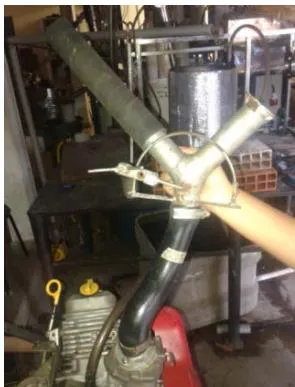
First the biomass inside the reactor is ignited with a gas torch burner. Within ten minutes, the gasifier flare is lit. The flare intensity and color start changing as well as the CO level of the poor gas. To start running the engine, the CO level must go up to 10%. To guarantee an approximate stoichiometric mixture of air/poor gas there is an Y shape mixing apparatus, see Figure 2. A load bank resistor (power range from 0.7 kW to 2.2 kW), was used to simulate the resistive load of the generator. Having stabilized the engine, (indicated by a close value of the 60 Hz frequency, as registered by the control equipment), the electrical resistances start being loaded, and all the data (power, biomass consumption, gas composition, elapsed running time, etc.) are registered. The biomass consumption is checked by means of a digital scale, considering that at the beginning of the tests, the biomass fills the fuel hopper to its maximum level. During the operation, new quantities of weighted biomass (in kg) are used to feed the gasifier, and the elapsed time is registered. The composition of the poor gas as well as that of the exhausted gases is evaluated using a Discovery G4 vehicle gas analyzer, fromAlfatest. The whole procedure is repeated for each of the four samples of wood pieces.
III. RESULTS AND DISCUSSION
a) The Biomass Moisture Content and Density
Table 1 shows the moisture content determined experimentally for the four biomass samples used to feed the gasifier. Table 2 presents the average density, experimentally determined, of the four wood samples. The values of the moisture content in Table 1 are all very similar, having magnitudes lower than . (To avoid producing lower biomass heating values, the moisture content should not be higher than , [52]).
| Sample | Essay/ Moisture Content(%) | |||
| 1 | 2 | 3 | Average (%) | |
| 1 | 10.992 | 10.442 | 9.042 | 10.159 |
| 2 | 8.280 | 10.149 | 9.304 | 9.244 |
| 3 | 9.868 | 9.793 | 10.670 | 10.110 |
| 4 | 8.274 | 9.752 | 9.544 | 9.190 |
In Table 2, we can see that sample 1 presents a density 19.7% larger than that of sample 3, which in turn has the second largest density among all the samples. Samples 2 and 4 have very similar density magnitudes. It should be noted that the average density of sample 1 is considerably higher as compared with the higher densities of different tropical species, see Reys et al. [53].
| Sample | Density (kg.m-3) | |||
| 1 | 2 | 3 | Average (%) | |
| 1 | 1083.754 | 1073.243 | 1063.308 | 1073.435 |
| 2 | 704.696 | 743.469 | 796.531 | 748.238 |
| 3 | 814.968 | 863.694 | 908.668 | 862.444 |
| 4 | 762.917 | 664.674 | 802.483 | 743.358 |
b) Proximate analysis of the biomass
Table 3 presents the results of the proximate analysis of the four different biomasses, using the ASTM E-1131 Standard Test Method for Compositional Analysis by Thermogravimetry. It shows that all the samples present high percentage of volatile matter, facilitating the conversion and the upgrading of the fuel, Digman et al. [54]; As a result of its smallest percentage of volatile matter, sample 4 presents the highest percentage of fixed carbon (FC). Thus, consonant with its FC magnitude, its HHV is larger than those of the other samples, which show similarly smaller values. It should be remembered that fixed carbon is the solid carbon of the biomass which remains in the char after it has been submitted to the devolatilization and pyrolysis processes, as pointed out by Basu [45]. On the other hand, the smallest percentage of ash was found in sample 3. In terms of moisture we can consider that all samples have similar contents.
| Sample | Volatile matter (%) | Fixed carbon (%) | Ash (%) | HHV (MJ/kg) | Moisture (%) |
| 1 | 91.470 | 4.390 | 4.140 | 15.780 | 11.090 |
| 2 | 88.544 | 6.259 | 5.197 | 15.976 | 12.550 |
| 3 | 96.215 | 2.186 | 1.599 | 15.760 | 11.730 |
| 4 | 82.556 | 15.413 | 2.031 | 18.305 | 11.620 |
c) Temperature Distribution Inside the Reactor
Table 4 shows the temperature registered inside the reactor, in the drying, pyrolysis, combustion and reduction zones. As expected, the temperatures mount till the combustion zone, declining at the reduction zone, and depending on the biomass, the temperature changes for each of the zones in question. This behavior directly influences the percentage of CO, and generation, see Figure 3. It shows the four types of biomass CO, and levels, at the engine's maximum power.
| Zone | Temperature (°C) | |||
| Sample 1 | Sample 2 | Sample 3 | Sample 4 | |
| Drying | 40.5 | 52.5 | 61.5 | 45.6 |
| Pyrolysis | 463.2 | 698.5 | 544.0 | 701.0 |
| Combustion | 954.4 | 1028.0 | 1079.0 | 1162.0 |
| Reduction | 860.0 | 844.0 | 952.7 | 1014.0 |
d) Behavior of the gases CO, and of the four biomass samples, with the engine running at maximum power In Figure 3, the CO level percentage increases as the sample volume mounts. This trend repeats for the percentage levels all along most part of the curve. It seems that the size of the sample interrupts this tendency. On the other hand, the , by reason of the and CO gases formation, is the only curve that goes down continuously, presenting an almost fixed slope.
e) The Poor Gas LHV as regards the electric power generation
Figure 4 presents the CO, and percentage as regards their biomas s densities. The tendency lines of gases CO, and present, as expected, an inverse behavior to lines. Comparison between the curves in Figures 3 and 4, given the fact that the formation of the gases CO and is enhanced by the increase in temperature, indicates that the flame zone intensity is much more limited by particle density, than by particle size. This fact is supported by the data in Tables 2 and 4, which show that lower densities correspond to higher temperatures in the pyrolysis zone. In consequence, the behavior in Figure 4, is characterized by an increasing tendency, as opposed to what occurs in Figure 3.
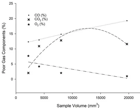
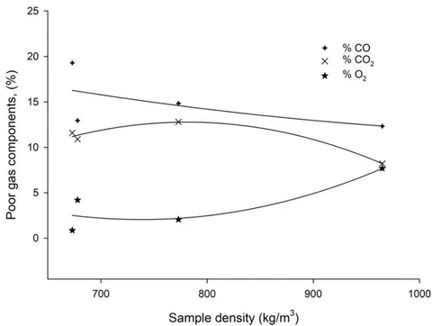
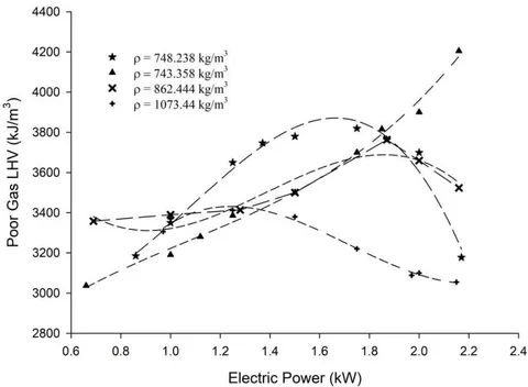
Figure 5 shows the heating value curves of the poor gas as a function of the electric power generation for the four samples. Differently from what happens with the majority of gasifiers, which use a blower to improve combustion, the enhancement of the flame inside the gasifier is mainly done by engine aspiration, acting as a driving force for gasification. As mentioned by Shin [29] the biomass size, as well as its calorific value may also influence the flame propagation speed. In Figure 5 we can see that considering the full range of variation of the electric generated power, the lowest LHV average is related to the samples having the highest average densities – 1073.435 kg.m and 862:444 kg.m - i.e. samples 1 and 3, respectively (see Table 2). Whereas sample 4 ( kg.m ), with the lowest average density and the largest LHV value, is the only one to show a continuous rising of the LHV. On the other hand, the second largest LHV value is produced by sample 2 ( kg.m ), which shows a rapid evolution of the generated electric power, but rapidly falls after reaching 1.7 kW. It should be noted that samples 4 and 2 present both the lowest density and volatile matter, see Table 3, while sample 4, shows the largest physical volume.
f) Biomass Specific Consumption
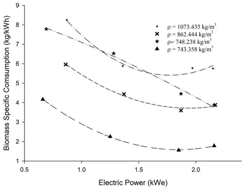
Figure 6 presents the biomass specific consumption in terms of the electric generated power, for the four different sizes of biomass. We see that, in general, the specific consumption of the biomass decreases with the increase of the generated power level, the lowest consumption being achieved by sample 4 type (considering the whole range of electric power generated), and sample 3 coming next (their densities are respectively 743.358 kg.m and 862.444 kg.m . For the electric power ranging from 0.9 kW to 2.2 kW, the consumption raised on average, 2.5 kg/kWh, when the gasifier was fueled with sample 1 type ( kg.m ). When the system is running with sample 4 biomass type, ( kg.m ) the consumption is the smallest, as compared with the other biomass types.
g) Efficiency of the system Gasifier/ Otto Cycle engine/Generator
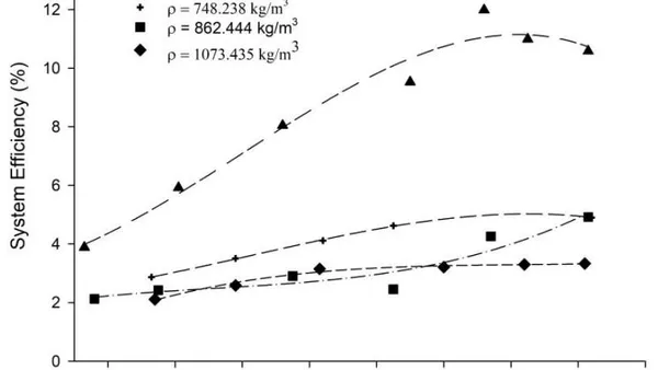
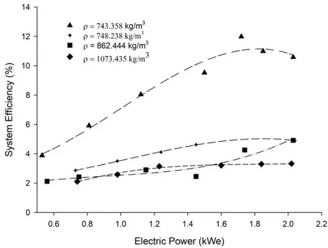
Figure 7 presents the plot for the system (gasifier/genset) efficiency, see Eq. (2), in terms of the generated electric power. It shows that from the smallest power up to , no matter the sample, the efficiency of the system tends to increase. From this point on, in three of the cases, the curves show a slight decrease as the electric power increases. The highest efficiency results from the use of sample 4 biomass , when the electric power reached 1.85 kW. In this connection, Tinaut et al. [55] using a one-dimensional stationary model of biomass gasification to study the effect of the biomass particle size on the gasification process in a downdraft fixed bed gasifier, showed that the maximum efficiency was achieved with a smaller particle size. In their case, the model was validated experimentally in a small-scale gasifier by comparing the experimental temperature fields, biomass burning rates with predicted results. However, the biomass density was not taken into consideration. In another model developed by Thunman et al. [24], concerning solid fuel conversion in a grate furnace using a fixed bed fuel bed, they concluded that particle density has small influence on the conversion rate, but noted that the particle size influenced the combustion behavior. In our case, however, small density has shown to have a beneficial influence on the various aspects of the gasifier, i.e. on its behavior and on the electricity production system, see Figure 6.
h) The Genset Efficiency Under Maximum Power Generation
The use of Eq. (3), gave as result , to generate 2 kW electric power. And as we have seen, the maximum efficiency of the system (gasifier/genset), , for generating electricity was 11.9%, which may be considered low. If the efficiency of the genset, , running on its maximum power is of 13.5%, i.e. 80%, of the power determined when run on gasoline, it becomes evident, from Eq. (3), that the gasifier efficiency, , is, in fact, 88.1%,
IV. CONCLUSIONS
The dissimilar curves in Figures 3 and 4, are an indication that we cannot analyze gasification performance referring just to biomass size, as Hernández et al. [30] did. Therefore, because of an existing correlation between biomass size and density, we can conclude, see Figure 3, that the larger the sample, the greater the CO percentage. Concerning the formation, it seems that there is a sample size limit (associated with a determined density value), when its production decreases caused by flammable shortage.
The most remarkable fact registered in the several tests concerning sample 4 ( ) is that it allows the maximum temperature of the reactor combustion zone. Analyzing its average figures of moisture content, density, and higher heating value, and comparing them with those of other samples, it is clear that sample 4 reunites the suitable property values to guarantee the adequate conditions for generating electricity, with the smallest biomass consumption. In other words, it shows the best effective energy efficiency among all the samples. It is also possible to conclude that the smaller the density, the slower the specific consumption, see Figure 6. Consequently, lower density helps the gases residence time raise, enabling a more efficient gasification, as indicated by the decreased concentration in , see Figure 4. According to Billaud et al. [56], formation occurs from combustion reactions and is directly bound up with the amount of . As a consequence of higher temperatures, there is an elevation in carbon monoxide concentration, a flammable gas, cf. Yin et al. [57]. It should be mentioned that similar results were obtained by Feng et al. [25], in studying a catalytic steam gasification of biomass. The only divergence is the behavior of , which decreased in a certain portion of the curve, due to the increase of the volume sample, as well as of its density. On the other hand, it should be noted that, given the HHV function of the CO level, the higher heating value of the poor gas made sample 4 biomass ( kg.m ), the only one capable of offering the system maximum efficiency in generating electric power.
Considering both the maximum efficiency of the system, and the efficiency of the engine running with poor gas, we can conclude that the gasifier efficiency with maximum power is about 88.1%, undoubtedly, a standout figure, Ptasinsky [58].
Funding sources
This research did not receive any specific grant from funding agencies in the public, commercial, or not-for-profit sectors.
Compliance with Ethical Standards:
The authors declare that they have no conflict of interest.