

I. INTRODUCTION
We have considered a method for creating a metamaterial in the radio frequency spectrum, where two parallel communication line elements are used as a cell of a metamaterial, one of which is a dielectric, the second is series-periodically connected odd single-wire open communication lines [1]. From this pair of a single element, a multilayer metastructure is created taking into account the phase of the backward waves. This method of creating Left handed materials (LHM) material [2] is broadband (non-resonant) and more versatile as applied to antenna technology than the second method of realizing a metamaterial in the form of a metastructure with a cell size much smaller than the wavelength of the transmitting signal, containing thin conducting rods and open frames [3-4].
As an example of resonator unit cells, we present the results , where a variety of cell shapes are considered in the form of broken and inserted into each other triangles, quadrangles, oval and other types, the sizes of which actually determine the narrowband characteristics, radiation pattern and gain of antennas. The external dimensions of such antenna cells reach 5-6 mm, with a gap of the order of 0.1-0.4 mm. The limited size of the unit cell does not allow mastering the creation of metamaterials in this way in the infrared (IR) and optical ranges.
Next, we will consider the possibilities of the first method for creating metamaterials in the IR and optical ranges . These works develop a new direction in the science of metamaterials and their applications in a wide field. This is due to the fact that Hyperboloid metamaterials make a scientific and practical contribution to optics as well as laser effects in their time. Nonlinear signal transfo-rmations using indefinite tensors and [13] are practically implemented in all areas of optics: in the processes of scattering, absorption, reflection, diffraction of light, in holographic effects, wave and waveguide phenomena, in focusing light and others.
Along with hyperboloid metamaterials, an alternative direction has been developing in recent years the use of magneto-optical properties of borate glasses with paramagnetic additives ions of , , , and others [14-18]. It should be noted the features of the radiation-optical and thermo-radiation properties of potassium-aluminoborate (KAB) glasses, activated by ions, in which, on the one hand, the radiation-optical properties are well studied [18], and on the other hand, they exhibit peculiar transformations of paramagnetic radiation-induced color centers into oxygen-containing medium of the form and , meaning 3x and 4x coordinated boron. The latter arise under the influence of X-ray and gamma irradiation of 60Co and temperature [17-18]. Radiation-induced color centers are and - respectively, electronic and hole color centers in borate glasses, interacting and constituting complexes of the type and other complexes with , ions [18].
It turned out that the simultaneous effect of the thermo radiation field causes a change in the coordination state of the activator ions in the medium in such a way that negative differential absorption is observed and, as a consequence, the medium becomes with a negative refractive index [19-20].
In this work, in contrast to , a method is proposed for studying RHM (Right handed materials) and LHM materials in order to create materials in the optical range, taking into account the analogies of oscillatory processes with wave processes . In the calculations, we will use computer programs . Some questions of the theory of an effective medium in metamaterials can be found in .
II. FEATURES OF THE ANALOGY OF AN OPTICAL WAVE FIELD WITH RADIO OSCILLATIONS IN A COMMUNICATION SYSTEM WITH DISTRIBUTED PARAMETERS
As a radio frequency analogy, let us consider an equivalent circuit of a communication system with distributed parameters with limited linear spatial dimensions. In this case, moving and backward waves will exist in the metamaterial located between the transmitter and the receiver, similar to the phenomena in a moving wave lamp or a backward klystron used on microwave waves.
For simplicity of calculations, consider a plane scalar monochromatic wave of the form
If we take both terms in expression (1), then we can consider nonlinear processes, if we take only the second term of equation (1), then we can consider linear processes. In this case, it is necessary to add a complex conjugate term. Formula (1) can be expressed as follows:
Where
Here \left|A\right|e^{i\phi} is the complex vibration amplitude.
The value is determined from the following relation
Which determines the projection of the direction of wave propagation
It can be shown that in a rectangular coordinate system the components of the vector are as follows:
Where the angle is chosen between k and the plane OYZ, between and the projection k on the plane OYZ. It can be seen from (5) that there are only two independent angular variables:
From (4) we find
hence
For the propagation of a plane wave in free space from the cutting plane of the transmitting antenna, the following condition must be met:
If (9) is not satisfied, then we get an inhomogeneous wave, which exponentially decays, at least along one of the coordinates . Such a wave is also a solution to the wave equation.
Note that equations and expressions (5) - (9) can be used to determine the radiation pattern of the transmitting antenna in a linear approximation.
Since the electromagnetic field in the form of a plane wave (8) with different parameters is a solution to the wave equation, the solution will also be in the form of a sum (integral) of fields of the form (8) for a three-dimensional system:
where is a complex function that describes the amplitude and phase of an individual plane wave with the direction of propagation, which determines the set of real variables , that is, all possible plane waves, including inhomogeneous ones.
Equation (10) is a generalization of the solution of the wave equation to the case of a nonplanar monochromatic wave, for example, for a spherical wave. From expression (10), one can pass to the real field by multiplying by and adding the complex conjugate term to the expression.
Let's solve the following problem: the values of the wave equation are given on the plane z=0 (the initial plane of the antenna location) of the directional pattern. It is required to find a solution of the wave equation for , which turns into a given function on the plane z=0.
From the conditions of Kirchhoff radiation on an infinite sphere of the wave field, this function should be equal to zero. From (10) we obtain the following
где
Having determined the frequency spectrum from (12) and , we find the boundary conditions at . It follows from (4.15) that for heterogeneous moving waves
and for z>0
For z < 0, we obtain a solution corresponding to backward waves
wherein
Formula (18) is valid for any value of z. The coordinates of points in the space x, y have the dimension of length l. The variables u1, u2 have the dimension of inverse wavelength cm-1 and correspond to spatial frequencies. Formulas (13) and (14) correspond to two-dimensional (D2) Fourier integrals [30]; formulas (15-18) correspond to the usual one-dimensional (D1) Fourier integrals.
III. CALCULATION OF THE SIGNAL TRANSMISSION SYSTEM BY WAVE ANALOG FOR RHM
Consider a signal transmission system over a wave channel. For calculations, we will use formulas (15) - (18) in a simplified one-dimensional (D1) version.
Recall that to calculate the signal spectrum (17), you need to know the specific form of the input function . As mentioned earlier, as we take the spectral dependence of KAB - glass [14-15, 18], and the shape of the absorption spectrum for a separate spectrum of the color center in the form of a Gaussian curve:
Where maximum amplitude of the Gaussian curve; the half-width of the Gaussian is formally equal to .
; Gaussian curve parameter; resonant frequency. Then formula (19) takes the following form
Where for simplicity of calculations for the RHM material the following designations are adopted:
After transformations and calculations using the theory of residues [30], we obtain
to simplify the solution of the problem; as a result, formula (23) is reduced to the following form
where
To determine the amount of deductions, change the following parameters . After the appropriate calculations, we arrive at the following equation
where through
IV. CALCULATION OF THE SIGNAL TRANSMISSION SYSTEM OVER THE WAVE CHANNEL TAKING INTO ACCOUNT THE PRESENCE OF LHM MATERIAL
Calculations carried out similarly to the previous paragraph, taking into account the LHM of the material in the III-square , lead to the following formulas:
For spatial spectrum and for field distribution
Where the physical meaning of the variable u is reflected: on the one hand, u - has the meaning of "spatial frequencies", having the dimension of the wavelength, on the other hand, it determines the propagation of plane waves, on which we mark the extended wave field. By analogy with (23) - (26) for a medium with a metamaterial (LHM), taking into account the change of variables and the application of the theory of residues [30], we obtain:
from which
real part,
Imagine part.
The following formulas were obtained for a metamaterial with a negative absorption coefficient:
V. CALCULATION RESULTS AND THEIR DISCUSSION
Using the previously obtained formulas (22), (28) - (30), we find the ratio of the spatial frequency spectra
where . To use a tabbed function [31]
transform
then (32) gets the following form
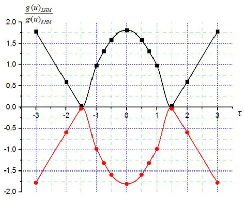
Calculations by formula (33) are presented in Fig. 1.a. Figure 1 shows that in the direction of propagation of "moving waves" (u=1), a spatial spectrum is observed (Fig. 1.a) with absorption of moving waves in the frequency
, there is an increase harmonics.
Calculations for depending on as well as for . This is due to the fact that in (33) and even functions. However, if we take into account the phase of oscillations according to (22), (26-30), then at we get
When u=k=-1,
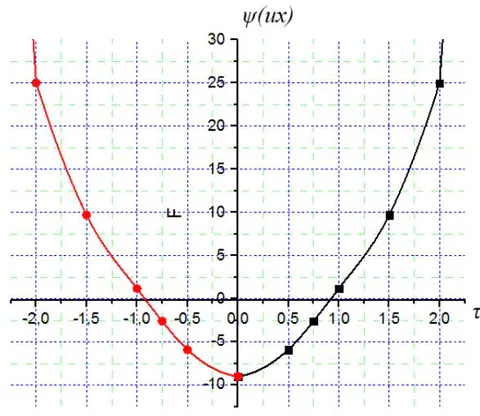
Calculations by formula (35) are presented in Fig.1.b, from the phase dependence of the spatial spectrum, it can be seen that the phase of the "moving wave" and "backward wave" changes its sign at .
Then let us determine the distribution of the amplitude of the electromagnetic field in a medium with a metamaterial (LHM) in relation to ordinary materials (RHM), for this we use formulas (25) and (31)
We transform this formula to a successful one for calculations using a tabulated function
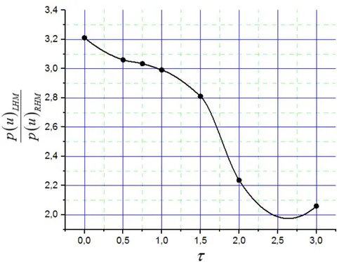
\frac{p(u)_{LHM}}{p(u)_{RHM}} = \sqrt{1 + \frac{\left[ 300 - 2.506\varphi^{-1}\left(-\frac{x^{2}}{2}\right) \right]^{2}}{2.8\cdot10^{4}}} \tag{1}\tag{37}Figure 2 shows a graph of dependence (37) depending on the relative frequency , in this case, taken as a unit of measurement. Table 1: Amplitude-frequency characteristic
| 0 | 0,5 | 0,75 | 1 | 1,5 | 2 | 3 | |
| 3,211 | 3,06 | 3,034 | 2,991 | 2,811 | 2,237 | 2,06 |
For this amplitude-frequency characteristic (Table 1), broadband and amplification is manifested among metamaterials (Fig. 2).
VI. CONCLUSIONS
It should be noted that small gain is not a problem, since in practice, both series connected and parallel elements are created, which can provide significant gain in comparison with the considered unidirectional linear system.
Thus, the problem of obtaining a metamaterial from amorphous glass has been theoretically solved. As samples, it is necessary to take amorphous films made of magneto-optical potassium-aluminoborate glass with additions of iron oxide, which provides the necessary metamaterial parameters during radiation processing, at sufficiently high temperature irradiation.
ACKNOWLEDGMENTS
We thank A N Yurasov for his help in our research.