I. INTRODUCTION
A turbine blade is the part which makes up the turbine segment of a gas turbine. The blades are responsible for extracting energy from the high temperature, high pressure gas produced by the combustor. The turbine blades are usually the restricting component of gas turbines. To survive in this difficult environment, turbine blades often use exotic materials like super alloys and many different methods of cooling, such as internal air channels, boundary layer cooling, and barrier coatings Blade fatigue is a major source of failure in steam turbines and gas turbines. Fatigue is caused by the stress induced by vibration and resonance within the operating range of machinery. To protect blades from these high dynamic stresses, friction dampers are used. Blades of wind turbines and water turbines are designed to operate in different conditions, which typically involve lower rotational speeds and temperatures. Gas turbine engine, a single turbine segment is comprised of a plate or center point that holds numerous turbine sharp blades. Turbine section is connected to a compressor section via a shaft (or "spool"), and that compressor section can either biaxial or centrifugal. The temperature is then greatly increased by combustion of fuel inside the combustor, which sits between the compressor stages and the turbine stages. The high-temperature and high-pressure exhaust gases then pass through the turbine stages. The stages separate energy from this stream, bringing down the pressure and temperature of the air. This process is very similar to how an axial compressor works, only in reverse. The number of turbine stages varies in different types of engines, with high-bypass-ratio engines tending to have the most turbine stages. The number of turbine stages can have a great effect on how the turbine blades are designed for each stage. Many gas turbine engines are twin-spool designs. Other gas turbines use three spools, adding an intermediate pressure spool between the high- and low-pressure spool. The high-pressure turbine is exposed to the hottest, highest-pressure air, and the low-pressure turbine is subjected to cooler, lower-pressure air. The difference in conditions leads to the design of high-pressure and low-pressure turbine blades that are significantly different in material and cooling choices even though the aerodynamic and thermodynamic principles are the same. Under these severe operating conditions inside the gas and steam turbines, the blades face high temperature, high stresses, and potentially high vibrations. Steam turbine blades are critical components in power plants which convert the linear motion of high-temperature and high-pressure steam flowing down a pressure gradient into a rotary motion of the turbine shaft. The present paper deals with the thermal stresses that arise due to temperature gradient within the blade material. The analysis is carried out under steady state conditions using Ansys software. The study has been conducted with three different materials stainless steel, Titanium alloy, Aluminium alloy.
II. LITERATURE REVIEW
In today's economic climate, cost pressure is a pervasive problem. One way to reduce costs is to carry out repair of single components within assemblies. In some applications, the regeneration can save up to of the costs compared to the replacement with remanufactured components. Due to the high potential in cost saving, most companies try to keep their knowledge in repair processes for themselves. Much effort is put into the improvement of processes in the maintenance, repair, and overhaul (MRO) of engines. An engine consists of approximately 30,000 components. Their repair takes a significant volume of the engine business with an increasing trend. Furthermore, Rupp indicates that the material costs add up to in the maintenance costs of engines. The repair or regeneration of components such as castings, seal fins/labyrinth, and notches is mostly carried out manually. Engine components of particular interest regarding the regeneration process are compressor, and turbine blades and vanes due to their high value. Most available references regarding the regeneration of those components concern the material deposit. Information on the recon touring is even harder to find.Nevertheless; this final shape cutting of a work piece is a crucial step regarding the later workpiece quality. Engine blades are an example for workpieces that have high requirements in accuracy and quality combined with a complex shape and difficult material conditions. The usual procedure for recon touring is characterized by a lot of manual working steps. This includes, e. g., manual grinding in the area of interfering contour. Achieving the final contour and a suitable surface topography is the most important aim. In order to limit the variety of occurring damages, Carter classifies these into basic groups. He describes and lists common failure mechanisms occurring at engine blades. Damage types are
Micro structural changes: due to high variations in temperature
Oxidation: due to chemical reactions of the workpiece material with the ambient air
Cracks: through high tensile stresses caused by thermal fatigue
Abrasion: through sand or small particles
Deformation: due to the impact of foreign objects or creep
Entire breakages: through foreign objects or thermo mechanical cracks or creep.
Any damage can be reduced to at least one of the three main causes: thermal influence, mechanical influence, or chemical influence. This paper in the following gives a literature review about regeneration processes related to the aviation industry. Moreover, it collects and generalizes detailed information on the machining point of view. The scientific basics extracted from the references can be transferred to other mechanical engineering sectors.
III. MODELLING OF SLAP AND SLIDER FOR FRICTION SURFACE
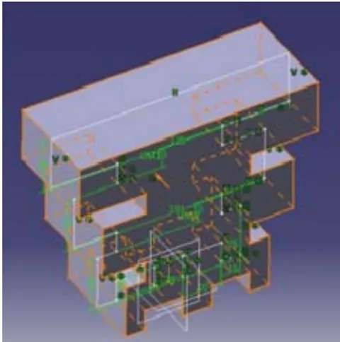
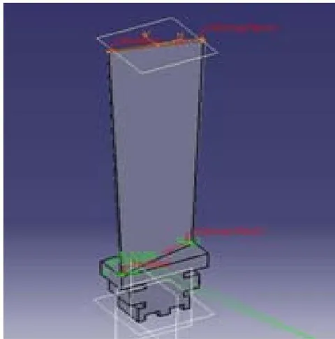
For Designing and analyzing an engineer must be familiar with the cause, which the manufacturing and thermal analysis done on the materials. Slap and slider are designed individually and assembled in order to obtain the final shape of the turbine blade. The slap and slider of the blade are designed as per the design standards using CATIA software as shown below:
IV. THERMAL ANALYSIS OF TURBINE BLADE
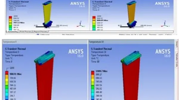
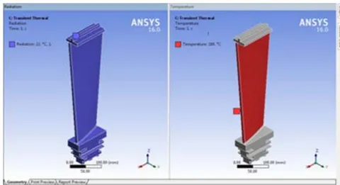
For thermal analysis of the turbine blade, ANSYS software is used. The blade is then analyzed sequentially with thermal analysis preceding structural analysis. The model is discretised using noded plane element & structural solid element. The thermal analysis is done by applying the temperature load of 80 °C on the front flat face of the model as shown in figure. Pertain the radiation load on the inward faces of the display, as laid out in fig. The inward faces are presented to air. The ambient temperature is 22 °C. The model is meshed and the boundary conditions applied for the thermal analysis. The model is meshed, boundary condition are applied for the analysis.
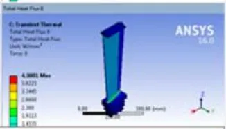
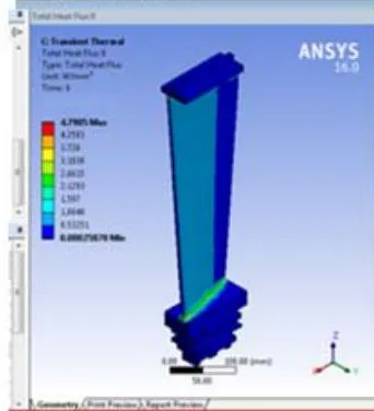
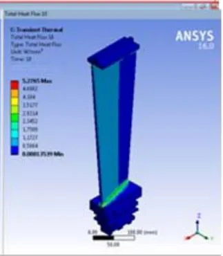
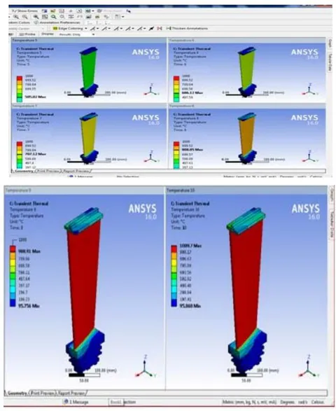
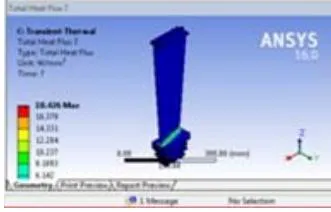
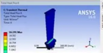
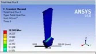
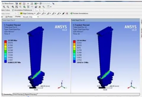
After the thermal boundary conditions are applied, it is now important to analyze the behavior of the model with respect to the boundary conditions applied. The analysis that is carried out for different materials is shown in following figures
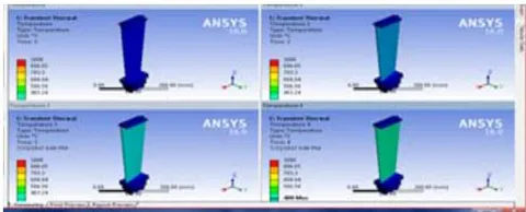
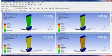
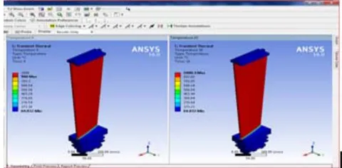
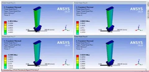
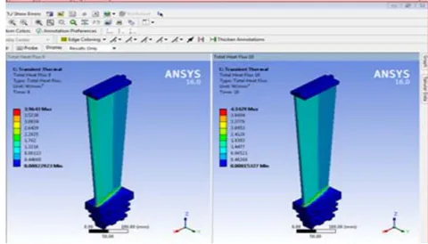
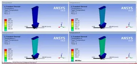
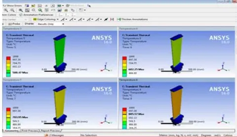
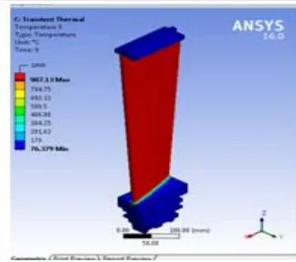
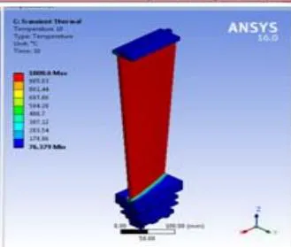
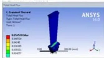
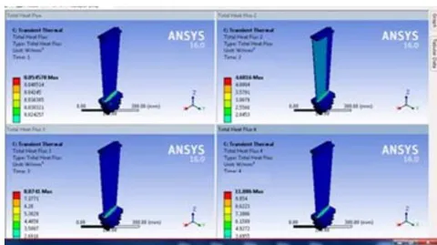
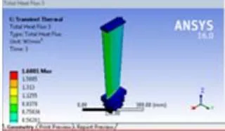
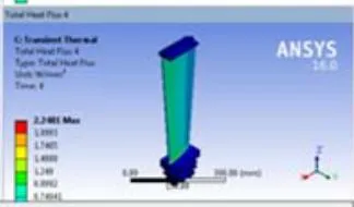
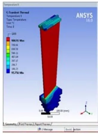
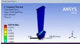
For Aluminum Alloy
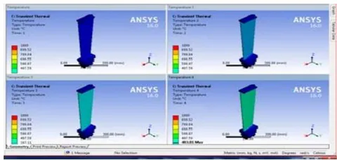
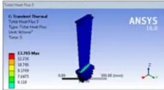
V. RESULT AND DISCUSSION
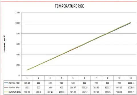
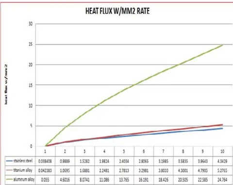
After the conduction of the thermal analysis on turbine blade is done using Ansys software. The results that are obtained with the rise in Temperature and Heat Flux by Temperature rise from 100 to 1000°C for different alloys is mentioned in the following table below:
| Heat Flux W/Mm2 | Temperature C | |||||
| S.No | Stainless Steel | Titanium Alloy | Aluminum Alloy | Stainless Steel | Titanium Alloy | Aluminum Alloy |
| 1 | 0.038408 | 0.042383 | 0.055 | 100.14 | 100.1 | 100.01 |
| 2 | 0.9889 | 1.0695 | 4.6016 | 200 | 200 | 200.9 |
| 3 | 1.5282 | 1.6881 | 8.0741 | 300 | 300 | 302.45 |
| 4 | 1.9824 | 2.2481 | 11.086 | 400 | 400 | 403.81 |
| 5 | 2.4034 | 2.7813 | 13.765 | 500 | 500.47 | 505.02 |
| 6 | 2.8065 | 3.2981 | 16.191 | 600 | 602.25 | 606.12 |
| 7 | 3.1985 | 3.8033 | 18.426 | 700 | 703.95 | 707.12 |
| 8 | 3.5835 | 4.3001 | 20.505 | 800 | 805.57 | 808.05 |
| 9 | 3.9643 | 4.7905 | 22.585 | 900 | 907.13 | 908.91 |
| 10 | 4.3429 | 5.2765 | 24.764 | 1000.4 | 1008.6 | 1009.7 |
The graphical representation for rise in Temperature and Heat Flux from C to C for different alloys are shown below
9. "Ch10-3". Hq.nasa.gov. Retrieved 2010-03-26.
Mattingly, Jack D. (2006). Elements of Propulsion: Gas Turbines and Rockets. AIAA Education Series. Reston, VA: American Institute of Aeronautics and Astronautics. p.
ISBN 1-56347-779-3.