The inability of pure relational DBMSs to meet the new requirements of the applications that have emerged on the web has led to the advent of No SQL DBMSs. In the last few years, significant progress has been made in integrating into relational DBMSs the features that are essential to consider those new requirements that primarily concern flexibility, performance, horizontal scaling, and very high availability. This paper focuses on the features that can enable relational DBMSs to provide applications with the flexibility to work with various non-relational data models while providing the guarantees of independence, integrity, and performance of query evaluation.
## I. INTRODUCTION
Data models are used in database technology: (1) To define the logical structure of the content of a database, (2) To provide DBMSs with the capability to maintain the integrity of that content, and (3) To provide an abstract language for the manipulation of that content.
[1] considers that each data model characterizes, using four sets (T, S, O, C) of its own, a virtual machine with which the users of the database interact, where: T is a set of data types, S is a set of data structure types, O is a set of data operation types, and C is a set of integrity constraint types.
Conceptual models (such as UML [2] and the entity-relationship model [3]) and the pure relational model [4] are those that have been the subject of many theoretical studies about their set C. Consequently, those data models are the ones that offer the most possibilities to guarantee data quality and reliability thanks to the simple and complex types of integrity constraints contained in C [5-6].
In exchange, the pure relational model stores data in tabular relations made of rows where each column contains an atomic value. While such rigidity is very suitable for structured data describing non-complex entities in the real world, such rigidity is inappropriate for structured, semi-structured, unstructured, or hybrid data describing complex entities [5] or for data organized as a graph.
The other commonly used data models are alternative models of the pure relational model. Among them are [7-10] the nested relational model, the object-oriented model, the document-oriented model (XML [11] and JSON [12], for example), the graph-oriented model, the column-oriented model, and the key/value-oriented model. Those data models have been introduced in database technology with the primary purpose of providing greater flexibility than the pure relational model thanks to the kinds of data types, data structure types, and data operation types contained in T, S, and O, on the one hand, for describing the data structure of the complex entities and, on the other hand, for handling the variability in the data types and the data structure types due to data source diversity [9].
In exchange (see paragraph 3), those data models sacrifice data independence and typically consider only a subset of the simplest integrity constraint types of the pure relational model, such as primary, unique, and referential keys. Additionally, some of those data models induce other integrity constraint types, such as the integrity constraints on the materialization of relationships that most DBMSs ignore. Those data models, therefore, lead the DBMSs to sacrifice the guarantees of independence and integrity.
The guarantees, other than the guarantee of integrity, on which purely relational DBMSs have also focused concern: (1) Data independence, (2) Confidentiality, (3) Simultaneous access to data, (4) Data security after an incident, (5) Performances in terms of possibilities of handling high volumes of data and in terms of data access speed, (6) The adequacy of the access interface for data manipulation according to the relational approach.
After the adoption of those purely relational DBMSs, new types of applications with new requirements that those purely relational DBMSs are unable to satisfy have emerged on the web.
Indeed [9], to guarantee data consistency and to avoid storage anomalies, the primary purpose of the techniques used in the design of a pure relational database is to eliminate, through a normalization process, any possibility of redundancy at the data level. For those new types of applications, it is, on the contrary essential to use redundancy and distribution to guarantee, on the one hand, the availability of the data whenever a failure happens and, on the other hand, the horizontal scaling of the services that the DBMSs offer to those applications.
In addition, to avoid the occurrence of anomalies generated on the data by the concurrency of the execution of the transactions and to ensure that recovery is possible whenever an incident occurs, pure relational DBMSs provide transactions with a runtime environment whose properties ensure ACIDity, i.e., Atomicity, Consistency, Isolation, and Durability. When the data are duplicated and distributed, DBMSs should, instead, provide a runtime environment with properties to ensure Consistency (C), Availability (A) for reads and writes, and tolerance for Network Partitioning (P). Brewer's CAP theorem states that a NoSQL DBMS can simultaneously provide only two properties [10].
As a result, new types of DBMSs (the object-oriented DBMSs [8] and the NoSQL DBMSs [9]), purely non-relational, have been designed to provide an adequate response to the rigidity of the pure relational model and those new requirements by relying on the alternative data models of the pure relational model and by moving away from its strengths in favor of the improvement of performances, of the scaling, and of the availability.
Simultaneously, an evolutionary approach has also emerged. The ambition of that approach is to integrate new features in the relational DBMSs to consider the requirements relating to the logical structure of databases [13,14] as well as the requirements relating to performances, scaling, and very high resistance to failures [15,16] while preserving the benefits of the pure relational model.
The guarantees pursued in that evolutionary approach concern: (1) Data independence, (2) Flexibility to work with various non-relational data models, (3) Data consistency, (4) Efficiency of data physical access, (4) Application scaling, (6) Availability for read and write operations, (7) Resistance to network partitioning whenever an outage happens.
In this paper, we focus on the ANSI/SPARC architecture [17] on which that evolutionary approach should rely to allow relational DBMSs to offer each application the flexibility to work with its preferred non-relational data model without sacrificing the guarantees of independence, integrity, and efficiency of evaluating queries on the database.
The explicit adoption of the restrictions of this ANSI/SPARC architecture of the schemata by a DBMS leads applications to manipulate a database by relying on a non-relational model, whereas the data model used to model that database internally is the pure relational model.
Take the view that data mapping means: redefining, using another data model, the data representation defined by relying on a given data model. The contribution of this paper is that it shows that with this ANSI/SPARC architecture of the schemata, it is possible to implement a process of data mapping that allows applications to manipulate a database according to the approach they prefer, whereas internally, that database is manipulated at the logical and physical levels as if it was a nested-relational database, with all the resulting benefits on the independence, integrity, and query evaluation efficiency guarantees. That process of data mapping is performed by relying on a relational database organized at the logical and physical levels for fast access to the abstract data that describe the complex real-world entities and by reusing the frameworks developed as part of relational database technology, thus preserving the results of investments made around that technology since its advent in 1970.
In the following, we address successively: (1) For illustration purposes, the rules commonly used to redefine the representation of a database, defined by relying on the UML conceptual model, using, on the one hand, the pure relational model as described in SQL2, and on the other hand, the object-relational and XML models as described in SQL3, while focusing on the consequences on the integrity of relationships, (2) The logic behind the ANSI/SPARC architecture of schemata on which evolutionary approaches must rely, (3) The mapping of the data that this architecture allows to implement at the logical and physical levels, (4) The comparison of that architecture where the database used at the logical level is modeled using the pure relational model to architectures where it is modeled using an extended relational model, XML, JSON, or a data model that leads to a logical implementation using the nested relational model.
## II. RULES FOR TRANSFORMING A CONCEPTUAL SCHEMA INTO A RELATIONAL LOGICAL SCHEMA
Fig.1 outlines the essential rules commonly used to derive a relational logical schema from the UML conceptual schema of a database [18]. In those derivation rules, the materialization of the relationships of the conceptual schema and the materialization of the deductible integrity constraints of their cardinalities, as well as the materialization of inheritance relationships, are carried out using foreign keys whose semantics allow the DBMSs to ensure the data integrity as defined by the conceptual schema.
In those rules, foreign keys are underlined and marked with the symbol \*\* when they must respect the unique integrity constraint or the symbol $^+$ otherwise.
A relational logical schema derived from those rules describes the perception that enables database manipulation according to the relational approach and the perception required to guarantee data independence and integrity.
## III. RULES FOR TRANSFORMING A CONCEPTUAL SCHEMA INTO AN OBJECT-RELATIONAL OR XML LOGICAL SCHEMA
The main rules [18], based on the semantics of the new concepts of SQL3 [13], for transforming a UML conceptual schema into an object-relational schema are defined in Fig.2. Rules that involve logical pointers are surrounded. Those rules are intended to facilitate the manipulation of the database according to the object-oriented approach.
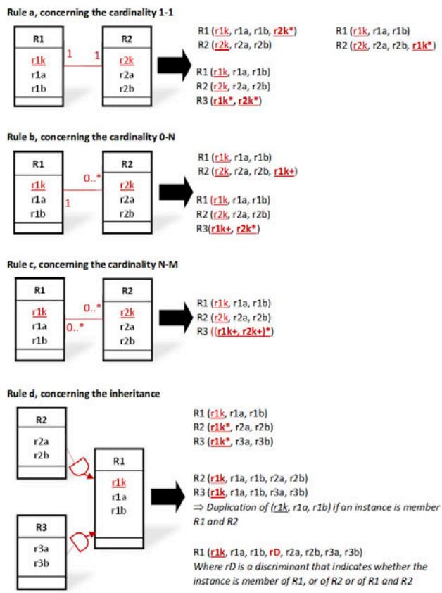 Fig. 1: Main Rules for Transforming a UML Conceptual Schema to a Relational Logical Schema
In those rules of Fig. 2:
1. "Ri (ria, rib,...) should be interpreted as denoting an object-relational table named "Ri" characterized by its atomic, composed, or relation-valued attributes named "ria, rib,..."
2. "RiTuple (ria, rib,...) should be interpreted as denoting a composed attribute characterized by its atomic, composed, or relation-valued attributes named "ria, rib,..."
3. "RiTupleSet (ria, rib,...) should be interpreted as denoting a relation-valued attribute containing a set of tuples characterized each by its atomic, composed, or relation-valued attributes named "ria, rib,..."
4. "RiRef" should be interpreted as denoting an atomic attribute containing a reference to an object of the object-relational table "Ri", i.e., a logical pointer to that object.
5. "RiRefSet (:RiRefType)" should be interpreted as denoting a relation-valued attribute containing a set
of references to the objects of the object-relational table "Ri", i.e., a set of logical pointers to those objects, where the type of those logical pointers is denoted by "RiRefType".
6. "rik*" should be interpreted as denoting a foreign key corresponding to the primary key of the table "Ri" that respects the uniqueness integrity constraint.
7. "rik+" should be interpreted as denoting a foreign key corresponding to the primary key of the table "Ri" that does not respect the uniqueness integrity constraint.
8. "RiRefSet (rik)" should be interpreted as denoting a relation-valued attribute containing a set of tuples where each tuple contains a value of the foreign key "rik" corresponding to the primary key of the table "Ri".
The rules based on foreign keys are applicable for deriving an XML logical schema from a conceptual schema, as defined in SQL3 [14], by considering that the tags of the XML elements and attributes have been omitted for each XML document. In addition, it should also be considered that for an object-relational table named "Ri", the type of an attribute can be XMLTYPE and thus contain an XML document stored (as an atomic value) with all its tags in the binary format of XML
and managed using the technology of the document-oriented DBMSs. Therefore, in an object-relational table, the content of an object or attribute can be, respectively, an XML document shredded in several attributes, or an XML document stored in a single attribute.
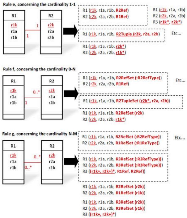 Fig. 2: Main Rules for Transforming a UML Conceptual Schema to an Object-Relational or XML Logical Schema
Those rules depict that the object-relational model and the XML model give the possibility of materializing each relationship by a set of pairs of unidirectional semantic links where in each pair, each link must be the inverse of the other, despite that the semantics of the concepts used, namely the concepts of logical pointer and foreign key, does not say how DBMSs should do to ensure the integrity of those links.
Furthermore, the data's logical structure based on the object-relational and XML models arises from design decisions that depend on both the data's semantics and the ways the user's applications intend to process those data but not only on the data's semantics, as for data's logical structure based on the relational model. After a change in the hierarchical structure of the data in the logical schema, the developer may be forced to modify the application logic accordingly [19].
## IV. THE LOGIC BEHIND THE ARCHITECTURE OF THE SCHEMATA IN THE EVOLUTIONARY APPROACH
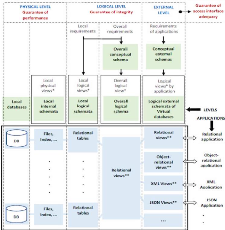
Fig. 3 schematizes the ANSI/SPARC architecture of the schemata on which evolutionary approaches should rely. One of the key features of that architecture is that it forces to decouple, on the one hand, the description concerning the perception that aims at facilitating data manipulation by applications and, on the other hand, the description of the perception induced by the database used internally for ensuring independence and integrity.

View* for perception | View** for virtual or derived table Fig. 3: The ANSI/SPARC Architecture of the Schemata, Which Provides Integrity and Independence Guarantees
Since the pure relational model is the one where T, S, O, and C offer the most possibilities to guarantee independence and integrity, that architecture leads to doing so that the perception induced by the database used internally to ensure independence and integrity can only be described using a pure relational logical schema.
As for the perception that aims to facilitate the manipulation of the database by an application, that architecture makes it only possible to describe that perception by relying on an external logical schema and using a data model where T, S, O, and C offer the required flexibility to model and manipulate the database used internally according to the approach that the application prefers, regardless of the possibilities provided by C.
Depending on the query, data manipulated by that application according to its preferred approach are determined dynamically and efficiently (see paragraphs 6 and 8) from the data stored in the pure relational database used internally to guarantee independence and integrity.
That ANSI/SPARC architecture of the schemata then leads to data mappings at the logical and physical levels. Those data mappings are required: (1) when designing the relational overall logical schema of the database, (2) when designing a physical database, (3) when designing the external logical schema of an application, (4) and when generating and optimizing the logical execution plan of a query.
## V. DATA MAPPING IN THE DESIGN PROCESS OF THE OVERALL RELATIONAL LOGICAL SCHEMA
The overall relational logical schema that defines a database used internally intended to be manipulated according to non-relational approaches can be derived simply from an overall conceptual schema by bringing out in that conceptual schema the whole-part relationships arising from the perception of the real-world's complex entities. For each real-world's complex entity denoted by "E1", all the other entities whose existence of their instances depends on an instance of "E1" must be identified by relying, as proposed in [3], on the concept of "existence dependency" of one entity on another and the concepts of "regular" (entity/relationship) and "weak" (entity/relationship).
Let's take the real-world's entities "Employee" and "Child" as examples. Each instance of "Child" depends on the existence of one instance of "Employee". Therefore, the entity "Child" is a weak entity. In an overall relational logical schema derived from an overall conceptual schema, the tabular relations derived from the existence dependency of "Child" on "Employee" must be "Employee (E-no, E-name, E-age,...) and "Child (E-no+, Child-name, Child-age,...) where "E-no" in the tabular relation denoted by "Child" is a foreign key. Notice that in Fig.1, this is a variant of the first of the two transformation possibilities defined by rule b, where the foreign key is part of a primary key. That rule allows us to describe, in the relational logical schema, the data about each complex entity of the real world using a hierarchy of tabular relations linked by foreign keys, where each abstract data that describes one instance of that complex entity must be stored in a hierarchy of rows distributed in those tabular relations.
The purpose of that rule, which says how to map each instance of a complex entity in the relational database used internally, is to result, as described in the next paragraph 6, in a physical organization of that database, which can guarantee fast access to each abstract data that describes an instance of a complex entity.
## VI. DATA MAPPING IN THE DESIGN PROCESS OF THE PHYSICAL DATABASE
The primary purpose of the design process of a physical database is to make explicit how each abstract data describing the instance of one complex entity should be organized and stored on the physical storage device to make physical access to that abstract data fast. As we saw in paragraph 5, each abstract data is stored in a hierarchy of rows distributed in tabular relations connected by foreign keys.
To achieve this, the two leading families of techniques developed within the framework of the pure relational DBMSs for the data physical storage structures on the disks can be reused and improved, i.e., physical clustering and indexes.
### a) Physical Clustering
The main choices, which can make fast physical access to each abstract data describing one instance of a complex entity, are:
1. Creating a table cluster for each regular (entity/ relationship) defined in the conceptual schema. The role of such a cluster is to group all the tabular relations connected by foreign keys, where the abstract data about the instances of that regular (entity/relationship) must be stored.
2. Storing each abstract data made of a hierarchy of rows (scattered across those tabular relations) in one or more contiguous pages of that cluster. That storage renders unnecessary the need to perform join operations for grouping those rows, which reduces to a strict minimum the average time to access all or part of each complex abstract data.
3. Implementing logically and physically those table clusters using the nested relational model [7]. The main benefit of that implementation is that this data model expands the sets T, S, and O of the relational model to overcome its limitations. As a result, this data model allows: (i) to describe each complex entity of the real world using a not decomposed complex abstract data (defined as a whole-part), (ii) to define a simple nested expression to recursively
apply the selection and projection operators to attributes nested at any level in the structure of that abstract data, (iii) to simplify that nested expression logically, and (iv) to evaluate, at the lowest possible cost, the resulting optimized nested expression, without any join operations.
When evaluating a query, those choices allow us to manipulate logically the database used internally as if it was a nested relational database where each table cluster is represented using a single nested relational table where the content of each row is a logical implementation of an abstract data stored in a hierarchy of rows of the tabular relations of the relational database, with all the benefits resulting in terms of performance.
Fig. 4.a contains as an example the conceptual schema, defined using the entity-relationship model [3], of a complex regular entity denoted by "rx" on which depend the weak entities denoted by "ry", "rz", and "rw".
The schemata of the tabular relations of the cluster, required for storing the abstract data about the instances of that entity "rx", are 'rx (A), ry (A+, B), rz (A, B)++, C), rw (A+, D, E'). As for the schema of the nested relational table that represents that cluster according to the syntax proposed in [7], it can be defined as follows: rx (A, ry (B, rz (C)), rw (D, E)).
Fig. 4.b schematizes, as an example, in one page of that cluster, the data layout of one abstract data about an instance of that entity "rx". This figure depicts that this instance of that complex entity "rx" is described by a hierarchy of rows consisting of one row from the tabular relation "rx", two rows from the tabular relation "ry", three rows from the tabular relation "rz", and two rows from the tabular relation "rw", connected by foreign keys. This figure also depicts that those rows are stored in a tree-like data structure according to the rules of the nested relational model. Each node contains a row consisting of atomic columns, subsets of pointers to child nodes where each subset corresponds to a relation-valued column, and pointers to the parent node and sibling nodes for easing navigation.
Physical storage of the rows of the relational database used internally inside the pages of the physical storage devices by following that approach is an improvement of the traditional approach. In that approach, rows are not stored only sequentially (ordering them or not). Rows are also logically organized within the pages in terms of tree-like data structures for rows that concern complex abstract data and linear data structures for rows that concern the same tabular relation.
The indexing of a tabular relation as well as access using an index to all or part of one abstract data stored inside a page within a tree-like data structure can be achieved, on the one hand, by creating a dictionary of table clusters containing, for each table cluster, the identifier of each table of that cluster, the type of that table (regular or weak), and its primary key, and on the other hand, by allocating, in the header of each page, an entry for each row within that page containing the identifier of the concerned table, the value of the primary key of that row, and its beginning address within that page.
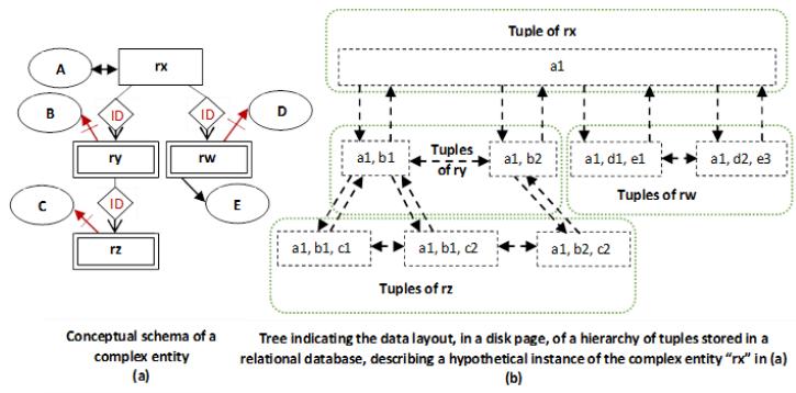 Fig. 4: Illustration of the Storage Structure in a Disk Page of Data about a Complex Entity Stored Logically in a Relational Database
### b) Indexes
Depending on a query complexity on a virtual database, its evaluation in an efficient way may require at the physical level to access the tabular relations where data are stored by following combinable different approaches:
1) A sequential approach allowing to traverse the rows of a tabular relation in a predetermined order.
2) An associative approach allowing access in a tabular relation to a set of rows qualified by the values of a subset of columns.
3) A navigational approach, allowing navigation from one row of a tabular relation towards rows in other tabular relations related in some way.
4) An approach, path expression oriented, allowing for each given path "Ti.a1.a2....an. x", derived from a hierarchy of class (or user-defined structured type) attributes, as that hierarchy is defined in [20], to determine either the set of rows of the tabular relation "Ti" or the set of the instances (either partial or not) of that path, related in the two cases to a given value of the attribute "x".
At the physical level, many techniques for creating access paths to tabular relations have been defined to fulfill those needs. The best known are join indexes [21](essential for dynamically materializing relationships of complex entities or for performing table cluster joins efficiently), pointer chains [22], secondary indexes based on $\mathsf{B}+$ trees [23] and dynamic hashing [24-25], and bitmap indexes [26].
An expression of the nested relational algebra derived from a query (as that derivation is described in paragraph 8) can be executed efficiently thanks to, on the one hand, the physical organization of the database described in this paragraph, and on the other hand, extended frameworks of the relational DBMSs.
## VII. DATA MAPPING IN THE DESIGN PROCESS OF THE EXTERNAL LOGICAL SCHEMA OF AN APPLICATION
When a DBMS adheres to the ANSI/SPARC architecture of schemata, which is schematized in Fig.3, the key role of the external logical schema of each application is to define a virtual database to allow that application to work with the data model it prefers. That virtual database is defined by creating, using a user-defined structured type, a custom-typed view for each regular (entity/relationship) defined in the conceptual schema, by following the derivation rules of Fig.
2.
To make it possible to manipulate that virtual database as if it was a nested relational virtual database, each of those typed views must be redefined using a schema that extends the schema of the nested relational table representing the cluster created at the physical level for the corresponding regular (entity/ relationship). The extension of that schema is carried out by adding the necessary attributes for the materialization of relationships.
Each cluster can therefore be considered as being the materialization of a typed view without the materialization of the relationships defined in the conceptual schema.
Consequently, the instances of a typed view in a virtual database do not have real existence as in the typed tables of a non-relational database. Those instances are derived dynamically from the tabular relations of the relational database used internally to ensure independence and integrity by relying on the data physical organization that results from using cluster and index concepts to make required computing fast.
More concretely, the data mapping in the design process of an external logical schema of an application is carried out by the database's administrator through the SELECT statements defining the typed views of the virtual database of that application. The SELECT statement defining a typed view must indicate how each instance of that typed view should be calculated dynamically using the relevant data stored in the relational database used internally for ensuring data independence and integrity. The role of triggers associated with a typed view must be to dynamically support the update operations of the instances of that typed view ("INSERT", "UPDATE", "DELETE") when the means put in place do not allow the DBMS to provide that support because this involves several tabular relations.
To facilitate the work of the databases' administrators, DBMS providers should instead consider offering the following possibility: indicating equivalently using new clauses or annotations in specification statements of the user-defined structured types, how for each user-defined structured type the value of each attribute of its instances must be calculated from the data stored in the relational database used internally for ensuring data independence and integrity, mainly concerning the relationships materialization. When evaluating a query formulated on a virtual database, the information contained in those specifications must provide the DBMS with the same possibilities as the SELECT statements and triggers associated with the typed views of that virtual database. This kind of approach for the definition of data mapping is followed, for example, in the object-relational mapper of Hibernate [27] and for storing shredded XML documents into object-relational tables [30] or relational tables [31].
For short illustrative purposes, by relying on a subset of rules presented in paragraphs 2 and 3, this can be achieved by specifying, for example.
1. For each user-defined structured type "R1" concerned: the type of the corresponding entity or relationship (regular or weak) in the conceptual schema, the name of the main table "T1p" of the overall relational logical schema, which is used for the derivation of its instances.
2. For each atomic-valued attribute "a" of that user-defined structured type "R1", whose type is a basic scalar type: the name of the column corresponding to it in the main table "T1p".
3. For each atomic-valued attribute "ai" of that user-defined structured type "R1", which is used to materialize a "1-1" relationship between "R1" and "R2" and whose type is a logical pointer type "R2RefType": the type of the relationship concerned, the name of the main table "T2p", which is used for the derivation of the instances of the structured type "R2", the name of the foreign key in "T1p", which refers to the main table "T2p" and which is used to calculate the value of that attribute "ai" corresponding to a logical pointer to an instance of "R2".
4. For each atomic-valued attribute "ai" of that user-defined structured type "R1", which is used to materialize an "N-1" relationship between "R1" and "R2" and whose type is a logical pointer type "R2RefType": the type of relationship concerned, the name of the main table "T2p", which is used for the derivation of instances of the structured type "R2", the name of the foreign key of "T1p", which refers to the main table "T2p" and which is used to calculate the value of that attribute "ai" corresponding to a logical pointer to an instance of " R2".
5. For each relation-valued attribute "ai" of that user-defined structured type "R1", which is used to materialize a "1-N" relationship between "R1" and "R2" and whose type "R2RefsetType" is a collection type of values of logical pointers: the type of relationship concerned, the name of the main table "T2p", which is used for the derivation of the instances of the structured type "R2", the name of the foreign key in "T2p", which refers to the main table "T1p" and which must for each instance of "R1" be used for the derivation of the value of that attribute "ai" corresponding to a collection consisting of logical pointers to the instances of "R2", which point back to that instance of "R1".
6. For each relation-valued attribute "ai" of that user-defined structured type "R1", which is used to materialize a "1-N" relationship corresponding to a composition relationship between "R1" and "R2" and whose type "R2TuplesetType" is a collection type of the instances of the structured type "R2": the type of the relationship concerned, the name of the main table "T2p", which is used for the derivation of the instances of the structured type "R2", the name of the foreign key in "T2p", which is part of its primary key and which refers to the main table "T1p" and which must for each instance of "R1" be used to calculate the value of that attribute "ai" corresponding to a collection consisting of the instances of the structured type "R2" linked to that instance of "R1".
7. For each relation-valued attribute "ai" of that user-defined structured type "R1", which is used to materialize an "N-M" relationship between "R1" and "R2" (using the user-defined structured type "R3") and whose type "R3RefsetType" is a collection type of values of logical pointers: the type of the relationship concerned, the names of the main tables "T2p" and "T3p", which are used for the derivation of the instances of the structured types "R2" and "R3", the name of the foreign key in "T3p" being part of its primary key, which refers to the main table "T1p", as well as that of the foreign key in "T3p" being part of its primary key, which refers to the main table "T2p", which both must be used for each instance of "R1" to calculate the value of that attribute "ai" corresponding to a collection consisting of the logical pointers to the instances of "R3", which point back to that instance of "R1".
This approach gives the DBMS the capability to play its role fully.
1. By ensuring the consistency of those specifications when creating a user-defined structured type in its catalog.
2. By ensuring, when creating each typed view, the automatic generation of the nested expression, which calculates the instances of its structured user-defined type from the tabular relations of the overall relational logical schema (including for each relationship concerned the calculation of its semantic links by ensuring that each link has an inverse link).
3. By ensuring, when executing the update operations of the instances of a typed view ("INSERT", "UPDATE", "DELETE"), the transformation of those operations into processes of updating the tabular relations from which those instances are derived.
## VIII. DATA MAPPING WHEN GENERATING AND OPTIMIZING QUERY LOGICAL EXECUTION PLAN
Paragraphs 6 and 7 showed that it is possible at the logical and physical levels to represent a virtual database (defined by the external logical schema of an application) using the nested relational model. This paragraph shows how that possibility enables fast execution of queries formulated on that virtual database. Formulating a SQL query for dynamic calculation of the instances of a typed view, as described in paragraph 7, may require using the various possibilities that SQL offers for nesting other queries, particularly in the SELECT clause but also in the FROM and WHERE clauses [28].
As [32] shows, DBMSs can represent this kind of SQL query containing nested queries by an expression of the nested relational algebra that defines a logical execution plan that uses tabular relations.
Conceptually, each instance of a typed view calculated using this kind of expression of the nested relational algebra can be manipulated as if it was stored in a nested relational table, even though the value of each of its attributes is determined dynamically from values contained in the tabular relations used internally to ensure independence and integrity guarantees.
Depending on its type, by applying the transformation functions provided for this purpose to the value of each attribute determined dynamically, those instances of a typed view can be perceived and manipulated by the developer as structured abstract data corresponding either to objects or to XML documents, for example.
Consider as an example the SQL statements in row 1 of Table 1 about the creation in the catalog of an Oracle DBMS [28] of the tabular relations "CUSTOMERS" and "ORDERS", corresponding to regular entities.
The SQL statements [29] for creating the object-relational typed view "CUSTOMERS_VOR" on the regular entity "CUSTOMERS" can be defined as in row 2 of Table 1.
The expression in row 3 of Table 1 is a nested expression derived for illustrative purposes from the SELECT statement that defines that typed view.
That expression is a logical execution plan for dynamically calculating all objects in the typed view named "CUSTOMERS_VOR". It calculates each instance of that typed view so that that instance can be perceived as if it was stored in a nested relational table. The values of the atomic-valued attributes named "CUSTNO" and "CUSTNAME" of that instance are defined as being the values of the columns having the same name in a row about a customer in the tabular relation named "CUSTOMERS". As for the value of its relation-valued attribute named "CUSTORDERS", it is defined as the result of projecting on column "ORDERNO" all the rows about that customer, selected in the tabular relation "ORDERS".
Each instance calculated using that expression is matched to an object of the typed view "CUSTOMERS_VOR" simply by applying the ORACLE transformation function "MAKE_REF() to each element of the relation-valued attribute named "CUSTOMERS".
Each query formulated using the data manipulation language of the data model used to describe a virtual database can be translated by the kernel of the DBMS to a logical execution plan based on nested relational algebra, using techniques comparable to those developed for standard SQL.
For example, consider the query in row 4 of Table 1 formulated using the extended SQL language of the object-relational model on the virtual database containing the typed view "CUSTOMERS VOR".
The expression in row 5 of Table 1 is an optimized expression of the nested relational algebra derived from that query that uses only the typed views of that virtual database.
The substitution in that expression of "CUSTOMERS_VOR", which denotes the name of a typed view of that virtual database, by the expression in row 3 of Table 1, which represents the SELECT statement of that typed view, leads to the expression in row 6 of Table 1, which uses only the tabular relations of the relational database used internally.
Simplifying that expression results in the expression of row 7 of Table 1, which corresponds to the optimized logical execution plan of the initial query, generated by considering the internal representation in tabular relations of the abstract data perceived and manipulated by the developer in his query as being objects.
## IX. RELATED WORK
We exclude from the scope of our analysis the object-relational mapping [27] that the deployment technologies of the web applications perform, outside the DBMS, to ensure, from a program, the persistence of the objects in a relational database. That very popular data mapping is a functionality of those technological offerings and not of the technology of the databases. Non-relational databases are intended to render obsolete the need for this mapping which is detrimental to performance.
The following compares the architecture of the schemata of Fig.3, where the model at the logical level is the pure relational model, to four broad categories of architectures where the model at the logical level is: (i) an extended relational model where in the tables the relation-valued columns contain nested tables, (ii) an extended relational model where in the tables the relation-valued columns contain XML documents or JSON documents, (iii) XML or JSON, (iv) leads to a logical implementation using nested relational tables.
In our comparison, we focus on the following three aspects: (i) the guarantee of independence, (ii) the guarantee of integrity, (iii) and the guarantee of performance when evaluating a query on the database.
### a) The Guarantee of Independence
The approaches to designing a database commonly used are based on two major schools of thought.
In the first stage of the oldest school, the database is modeled independently of the individual perception of applications. In this first stage, the designer's primary objective is to define, using a conceptual model, the perception of the actors of the enterprise independently of any technological choice. That school is best suited when integrity is a fundamental requirement and handling the difference between data types and data structure types required by different applications is an uphill task.
The second school developed recently at the same time as NoSQL DBMSs. In that school, the database is modeled at the same time as the design of an application by relying on a flexible data model, such as the document-oriented model, to consider the specific needs of that application in terms of data organization as soon as they appear or are challenged. That school is best suited for an application when handling the variability in data types and data structure types is an uphill task.
Table 1: Examples of Paragraph 8 for Illustrating the Transformation of a Query to a Logical Execution Plan
<table><tr><td>1</td><td>CREATE TABLE CUSTOMERS (CUSTNO NUMBER (5) PRIMARY KEY, CUSTNAME VARCHAR2 (30) NOT NULL); CREATE TABLE ORDERS (ORDERNO NUMBER (8) PRIMARY KEY, ORD_CUSTNO NUMBER (5) NOT NULL REFERENCES CUSTOMERS (CUSTNO));</td></tr><tr><td>2</td><td>CREATE TYPE CUSTOMER_T; CREATE OR REPLACE TYPE ORDER_T AS OBJECT (ORDERNO NUMBER (8), ORDERCUST REF CUSTOMER_T); CREATE OR REPLACE TYPE ORDER_T_LIST AS TABLE OF REF ORDER_T; CREATE OR REPLACE TYPE CUSTOMER_T AS OBJECT (CUSTNO NUMBER (5), CUSTNAME VARCHAR2 (30), CUSTORDERS ORDER T_LIST); CREATE OR REPLACE FORCE VIEW CUSTOMERS_VOR OF CUSTOMER_T WITH OBJECT IDENTIFIER (CUSTNO) AS SELECT c.CUSTNO, c.CUSTNAME, CAST (MULTISET (SELECT MAKE_REF (ORDERS_VOR, o.ORDerno) FROM ORDERS o WHERE o.ORD_CUSTNO = c.CUSTNO) AS ORDER_T_LIST) AS CUSTOMERS FROM CUSTOMERS c;</td></tr><tr><td>3</td><td>π [CUSTNO, CUSTNAME, π [ORDERNO](σ[ORD CUSTNO = CUSTNO](ORDERS)): CUSTORDERS](CUSTOMERS)</td></tr><tr><td>4</td><td>SELECT c.CUSTNO, c.CUSTNAME FROM CUSTOMERS_VOR c WHERE c.CUSTNO = 100;</td></tr><tr><td>5</td><td>π [CUSTNO, CUSTNAME](σ[CUSTNO =100](CUSTOMERS_VOR))</td></tr><tr><td>6</td><td>π [CUSTNO, CUSTNAME](σ[CUSTNO=100](π [CUSTNO, CUSTNAME, π [ORDERNO](σ[ORD_CUSTNO=CUSTNO](ORDERS)): CUSTOMERS)))</td></tr><tr><td>7</td><td>π [CUSTNO, CUSTNAME](σ[CUSTNO=100](CUSTOMERS))</td></tr></table>
The architectures of categories (i), (ii), (iii), and (iv).
Data mapping is typically accomplished in two steps within those architectures.
In the first step, data mapping consists of deriving the perception that facilitates the manipulation of the database according to the preferred non-relational approach from the conceptual schema or the kind of use case concerned. The designer's primary objective is to meet the requirements of developers by eliminating the drawbacks that arise from impedance mismatches and by adapting the data logical structure to how the processing is conducted.
In this first step, the way the database can be perceived and manipulated is captured using user-defined structured types that allow the information system to be perceived as being made of abstract data describing instances of complex entities in the real world, optionally by using flexible schemata, easy to modify.
In the second step, data mapping consists of deriving from the user-defined structured types a storage structure for a logical implementation of the instances of those user-defined structured types that can facilitate a physical implementation on the storage devices.
For architectures where the model at the logical level is an extended relational model, XML or JSON, this amounts in the first step to defining a non-relational logical schema and in the second step to implementing each non-relational table using a set of tabular relations where all columns are atomic-valued, optionally by storing in a binary format the XML and JSON documents. As in the architecture of Fig.3, this amounts to storing the data about each instance of a complex entity in several tabular relations connected by foreign keys. As a result, this makes it possible to reuse the frameworks of the pure relational DBMSs for query optimization and evaluation. When XML and JSON documents are stored in binary format, it is also possible to rely on a hybrid system that integrates the required features for modeling the complex data concerned according to the approach of the second school.
For architectures where the model at the logical level leads to a logical implementation using nested relational tables, this comes down in the first step to defining a non-relational logical schema that meets the developers' requirements and in the second step to derive a nested relational database from that non-relational logical schema.
Therefore, in those architectures of categories (i), (ii), (iii), and (iv), the logical schema of the database always stems from the perception required for a particular application and can make it more complex for another application to manipulate that database.
The architecture where the database is modeled internally using the relational model.
As far as this architecture is concerned, it is instead the derivation of the database used internally that is carried out first from the conceptual schema before the derivation for each application of the perception that facilitates the manipulation of that database according to the required approach. The primary goal is to define, regardless of the individual perception of the applications, the data logical organization, the integrity constraints, and the data physical organization that can guarantee fast access to each abstract data that describes one instance of a complex entity in the real world. It is more in line with the key objective of the ANSI/SPARC architecture of the schemata, which is to allow DBMSs to provide data independence guarantees. As a result, compared to architectures where the data model used internally is an extended relational model, XML, or JSON, that architecture ensures greater data independence. Additionally, that architecture allows partitioning the database into datasets, for which the best school for the design can be considered independently.
### b) The Guarantee of Integrity
Among the architectures considered in this paragraph, the most common are those of categories (i), (ii), and (iii) that implement SQL3 and those of category (iii) used by document-oriented NoSQL DBMSs. Those architectures do not allow to guarantee the integrity of relationships defined in conceptual schemata when those relationships are materialized using pairs of semantic links where in each pair, each link must be the inverse of the other. The reason for that significant drawback is that the semantics of the concepts used for materializing those relationships, namely the concepts of foreign key and logical pointer, do not indicate how DBMSs can guarantee the integrity of those relationships. To overcome that shortcoming, the architecture presented in that paper materializes those relationships in a virtual database. The resulting calculation is achieved (using rules that can be predefined and played by the DBMSs) using relevant data from the relational database used internally to ensure independence and integrity. The alternatives are: (i) either to materialize each relationship using in the logical schema two functions, such as each is defined as the inverse function of the other [8], (ii) or to define and implement path constraints [33].
Furthermore, the set of types of simple and complex integrity constraints that may be defined in a pure relational logical schema is a superset of each set of the types of integrity constraints that can be defined in a logical schema of an architecture of the categories (i), (ii), (iii), and (iv). One of the main benefits of the architecture of Fig.3 is that it allows the designer to define the custom view of an application by relying on any data logical model on which the architectures of the categories (i), (ii), (iii), and (iv) rely and by enforcing types of integrity constraints that this data logical model does not consider thanks to the overall relational logical schema of Fig. 3. For some use cases, this is an alternative to extending the set $C$ of the non-relational data logical models with complex integrity constraint types that are difficult to express and enforce.
### c) The Guarantee of Performance when Evaluating a Query on the Database
One of the main benefits of the schemata architecture of Fig. 3 is that it allows applications to manipulate the data according to the approach they prefer, whereas internally, that data is manipulated at the logical and physical levels as if it were stored in nested relational tables. In other words, this allows at the logical and physical levels to manipulate as efficiently as possible the data that describe the complex entities in the real world as if they have not been broken down and distributed in tabular relations.
In the architectures where the model at the logical level is an extended relational model, XML, or JSON, when the data describing complex entities in the real world are stored internally in several tabular relations, on the contrary, this makes query evaluation inefficient because of the join operations that can result.
It should be noted, however, that for the architectures where the model at the logical level is the pure relational model, an extended relational model, XML, or JSON, when the XML or JSON documents are stored internally in the binary format, the resulting performance benefits are those recognized for document-oriented DBMSs such as MongoDB.
The architectures where the model at the logical level leads to a logical implementation using nested relational tables make it possible to use nested relational algebra for better logical optimization of queries. Those architectures also lead to an implementation of the nested relational tables on the storage devices by storing each row of those tables (corresponding to one abstract data describing an instance of a complex entity) in one or more contiguous pages using a format close to that of the nested relational model. This ensures efficient query evaluation but requires implementing a new manager of abstract data (i.e., a new complex storage engine) responsible for providing an interface for manipulating those complex abstract data at the logical level and managing their physical storage using clustering techniques.
## X. CONCLUSION
In this paper, we focused on the features that should be built into relational DBMSs so they can provide applications with the flexibility to work with the non-relational data model they prefer without sacrificing guarantees of independence and integrity, as well as the guarantee of query performance. One of the most critical aspects of the features that have been integrated into the relational DBMSs in recent years to meet the requirements of horizontal scaling and very high availability [15, 16] concerns the resulting level of performance when evaluating queries that require a considerable number of join operations. This aspect can be addressed more effectively by dynamically applying the sharding and distribution techniques to table clusters instead of directly applying those techniques to tabular relations. That choice would allow extended relational DBMSs to give applications the flexibility to work with their preferred data storage models without sacrificing any benefit of the technology of the databases.
Generating HTML Viewer...
References
31 Cites in Article
E Eessaar (2007). Using Meta-modeling in order to Evaluate Data Models.
(2012). Information technology. Object Management Group Unified Modeling Language (OMG UML).
Peter Pin-Shan Chen,P-S (1976). The entity-relationship model—toward a unified view of data.
E Codd (1990). The relational model for database management.
C Date (2003). An Introduction to Database Systems.
J Vidaković (2018). Extended Tuple Constraint Type as a Complex Integrity Constraint Type in XML Data Model -Definition and Enforcement.
H-J Schek,M Scholl (1986). The relational model with relation-valued attributes.
R Cattell (2000). ODMG-93.
A Wajid (2019). Comparison between SQL and NoSQL Databases and Their Relationship with Big Data Analytics.
H Changlin (2015). Survey on NoSQL Database Technology.
(null). W3C XML Schema.
(2002). Information technology. Database languages SQL.
No ethics committee approval was required for this article type.
Data Availability
Not applicable for this article.
How to Cite This Article
Joachim Tankoano. 2026. \u201cProviding in RDBMSs the Flexibility to Work with Various Non-Relational Data Models\u201d. Global Journal of Computer Science and Technology - H: Information & Technology GJCST-H Volume 23 (GJCST Volume 23 Issue H2).
Explore published articles in an immersive Augmented Reality environment. Our platform converts research papers into interactive 3D books, allowing readers to view and interact with content using AR and VR compatible devices.
Your published article is automatically converted into a realistic 3D book. Flip through pages and read research papers in a more engaging and interactive format.
Our website is actively being updated, and changes may occur frequently. Please clear your browser cache if needed. For feedback or error reporting, please email [email protected]
Thank you for connecting with us. We will respond to you shortly.