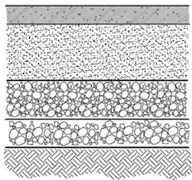
1. Subgrade (Road Bed)
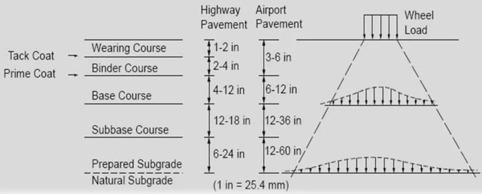
The subgrade is usually the natural material located along the horizontal alignment of the road and serves as the foundation of the pavement structure.
2. Subbase Course
Located immediately above the subgrade, the subbase component consists of material of a superior quality to that which is generally used for subgrade construction.
3. Base Course
Located immediately above the subbase, if a subbase course is not used. This course usually consists of granular materials such as crushed stone, crushed or uncrushed slag, crushed or uncrushed gravel, and sand.
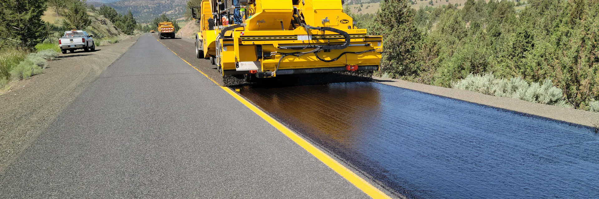
4. Surface Course
Constructed immediately above the base course, usually consists a mixture of aggregates and asphalt. It should be capable of withstanding high tire pressures, resisting abrasive forces due to traffic, providing a skid-resistant driving surface, and preventing the penetration of surface water into the underlying layers.
I. GENERAL PRINCIPLES OF FLEXIBLE PAVEMENT DESIGN
Assumed initially that the subgrade layer is infinite in both the horizontal and vertical directions, whereas the other layers are finite in the vertical direction and infinite in the horizontal direction.
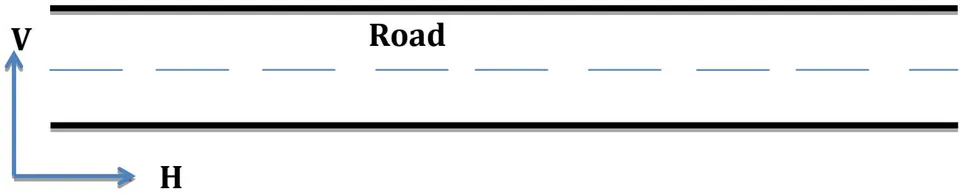
In the design of flexible pavements, the pavement structure usually is considered as a multilayered elastic system, with the material that may include the modulus of elasticity (E), the resilient modulus (R), and the Poisson ratio .
Applying of a wheel load causes a stress distribution; the maximum vertical stresses are compressive and occur directly under the wheel load. These decrease with an increase in depth from the surface.
II. AASHTO DESIGN METHOD CONSIDERATIONS
a) Pavement Performance
Structural performance is related to the physical condition of the pavement with respect to factors that hurt the capability of the pavement to carry the traffic load.
- These factors include cracking, faulting, unraveling, and so forth.
Functional performance is an indication of how effectively the pavement serves the user.
- The main factor considered under functional performance is riding comfort.
- To quantify pavement functional performance, a concept known as the serviceability performance was developed.
And Under this concept, a procedure was developed to determine the present serviceability index (PSI) of the pavement, based on its roughness and distress, which were measured in terms of the extent of cracking, patching, and rut depth for flexible pavements.
Two serviceability indices are used in the design procedure:
The initial serviceability index (pi) is the serviceability index immediately after the Construction of the pavement.
The terminal serviceability index (pt) is the minimum acceptable value before reconstruction is necessary.
b) Traffic Load
In the AASHTO design method, the traffic load is determined in Terms of the number of repetitions of an 18,000-lb (80 KN) the Single-axle load applied to the pavement.
This is usually referred to as: The Equivalent Single-Axle Load (ESAL).
A general equation for the accumulated ESAL for each category of axle load is
Where:
ESAL = Equivalent Accumulated 18,000-lb (80 KN) single-axle load.
AADT = First year annual average daily traffic.
Number of axles on each vehicle.
load equivalency factor for Single and Tandem axle.
Growth factor for a given growth rate and design period n.
365 = Convert from day to year.
Design lane factor.
| Name | Equation |
| ESAL Design lane | AADT × N × FEi × Grn × 365 × fd |
| Total ESAL | AADT × N × FEi × Grn × 365 |
| First Year ESAL Design lane | AADT × N × FEi × 365 × fd |
| Total ESAL First Year | AADT × N × FEi × 365 |
| Daily ESAL Design Lane | AADT × N × FEi × fd |
| Total Daily ESAL | AADT × N × FEi |
Table 19.4: Growth Factors
| Design Period, Years (n) | Annual Growth Rate, Percent (r) | |||||||
| No Growth | 2 | 4 | 5 | 6 | 7 | 8 | 10 | |
| 1 | 1.0 | 1.0 | 1.0 | 1.0 | 1.0 | 1.0 | 1.0 | 1.0 |
| 2 | 2.0 | 2.02 | 2.04 | 2.05 | 2.06 | 2.07 | 2.08 | 2.10 |
| 3 | 3.0 | 3.06 | 3.12 | 3.15 | 3.18 | 3.21 | 3.25 | 3.31 |
| 4 | 4.0 | 4.12 | 4.25 | 4.31 | 4.37 | 4.44 | 4.51 | 4.64 |
| 5 | 5.0 | 5.20 | 5.42 | 5.53 | 5.64 | 5.75 | 5.87 | 6.11 |
| 6 | 6.0 | 6.31 | 6.63 | 6.80 | 6.98 | 7.15 | 7.34 | 7.72 |
| 7 | 7.0 | 7.43 | 7.90 | 8.14 | 8.39 | 8.65 | 8.92 | 9.49 |
| 8 | 8.0 | 8.58 | 9.21 | 9.55 | 9.90 | 10.26 | 10.64 | 11.44 |
| 9 | 9.0 | 9.75 | 10.58 | 11.03 | 11.49 | 11.98 | 12.49 | 13.58 |
| 10 | 10.0 | 10.95 | 12.01 | 12.58 | 13.18 | 13.82 | 14.49 | 15.94 |
| 11 | 11.0 | 12.17 | 13.49 | 14.21 | 14.97 | 15.78 | 16.65 | 18.53 |
| 12 | 12.0 | 13.41 | 15.03 | 15.92 | 16.87 | 17.89 | 18.98 | 21.38 |
| 13 | 13.0 | 14.68 | 16.63 | 17.71 | 18.88 | 20.14 | 21.50 | 24.52 |
| 14 | 14.0 | 15.97 | 18.29 | 19.16 | 21.01 | 22.55 | 24.21 | 27.97 |
| 15 | 15.0 | 17.29 | 20.02 | 21.58 | 23.28 | 25.13 | 27.15 | 31.77 |
| 16 | 16.0 | 18.64 | 21.82 | 23.66 | 25.67 | 27.89 | 30.32 | 35.95 |
| 17 | 17.0 | 20.01 | 23.70 | 25.84 | 28.21 | 30.84 | 33.75 | 40.55 |
| 18 | 18.0 | 21.41 | 25.65 | 28.13 | 30.91 | 34.00 | 37.45 | 45.60 |
| 19 | 19.0 | 22.84 | 27.67 | 30.54 | 33.76 | 37.38 | 41.45 | 51.16 |
| 20 | 20.0 | 24.30 | 29.78 | 33.06 | 36.79 | 41.00 | 45.76 | 57.28 |
| 25 | 25.0 | 32.03 | 41.65 | 47.73 | 54.86 | 63.25 | 73.11 | 98.35 |
| 30 | 30.0 | 40.57 | 56.08 | 66.44 | 79.06 | 94.46 | 113.28 | 164.49 |
| 35 | 35.0 | 49.99 | 73.65 | 90.32 | 111.43 | 138.24 | 172.32 | 271.02 |
EX: If the value of design period years , and annual growth rate , Find ?
From above table
From Equation
- From table 19.3a & 19.3b
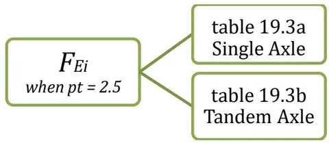
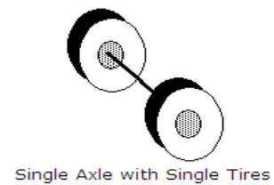
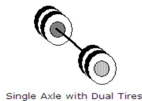
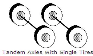

Table 19.3a: Axle Load Equivalency Factors for Flexible Pavements, Single Axles, and of 2.5
| Axle Load (kips) | Pavement Structural Number (SN) | |||||
| 1 | 2 | 3 | 4 | 5 | 6 | |
| 2 | .0004 | .0004 | .0003 | .0002 | .0002 | .0002 |
| 4 | .003 | .004 | .004 | .003 | .002 | .002 |
| 6 | .011 | .017 | .017 | .013 | .010 | .009 |
| 8 | .032 | .047 | .051 | .041 | .034 | .031 |
| 10 | .078 | .102 | .118 | .102 | .088 | .080 |
| 12 | .168 | .198 | .229 | .213 | .189 | .176 |
| 14 | .328 | .358 | .399 | .388 | .360 | .342 |
| 16 | .591 | .613 | .646 | .645 | .623 | .606 |
| 18 | 1.00 | 1.00 | 1.00 | 1.00 | 1.00 | 1.00 |
| 20 | 1.61 | 1.57 | 1.49 | 1.47 | 1.51 | 1.55 |
| 22 | 2.48 | 2.38 | 2.17 | 2.09 | 2.18 | 2.30 |
| 24 | 3.69 | 3.49 | 3.09 | 2.89 | 3.03 | 3.27 |
| 26 | 5.33 | 4.99 | 4.31 | 3.91 | 4.09 | 4.48 |
| 28 | 7.49 | 6.98 | 5.90 | 5.21 | 5.39 | 5.98 |
| 30 | 10.3 | 9.5 | 7.9 | 6.8 | 7.0 | 7.8 |
| 32 | 13.9 | 12.8 | 10.5 | 8.8 | 8.9 | 10.0 |
| 34 | 18.4 | 16.9 | 13.7 | 11.3 | 11.2 | 12.5 |
| 36 | 24.0 | 22.0 | 17.7 | 14.4 | 13.9 | 15.5 |
| 38 | 30.9 | 28.3 | 22.6 | 18.1 | 17.2 | 19.0 |
| 40 | 39.3 | 35.9 | 28.5 | 22.5 | 21.1 | 23.0 |
| 42 | 49.3 | 45.0 | 35.6 | 27.8 | 25.6 | 27.7 |
| 44 | 61.3 | 55.9 | 44.0 | 34.0 | 31.0 | 33.1 |
| 46 | 75.5 | 68.8 | 54.0 | 41.4 | 37.2 | 39.3 |
| 48 | 92.2 | 83.9 | 65.7 | 50.1 | 44.5 | 46.5 |
| 50 | 112.0 | 102.0 | 79.0 | 60.0 | 53.0 | 55.0 |
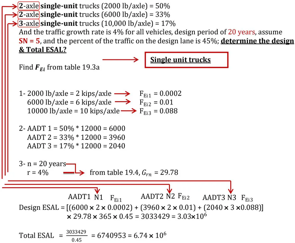
Ex 1:
Traffic (AADT) in both directions on the Highway during the first year of operation will be 12,000 with the following vehicle mix and axle loads.
Ex 2:
The presentAADT (in both directions) of 6000 vehicles is expected to grow at per annum. Assume and the percent of the traffic on the design lane is , the design life is 20 years.
If the vehicle mix is:
(3-axle tandem, 4-single axle) trucks (10000 lb/axle) = 60%
2-axle single-unit trucks (5000 lb/axle) = 30%
(3-axle single-unit, 2-axle tandem) trucks (7000 lb/axle) = 10%
Determine:
- a-Daily Design ESAL
- b- Total ESAL for the First year
- c- Total ESAL
- d- Design ESAL for (10000 lb/axle)
- e- Daily Total ESAL for (7000 lb/axle)
Solution:
1- 10000 lb/axle = 10 kips/axle
single
tandem

[5000 , = 5 , \longrightarrow \quad F_{} , = = 0.008]
7000 lb/axle = 7 kips/axle F single =
tandem
2-AADT1
AADT2 = 30% × 6000 = 1800
AADT3 = 10% × 6000 = 600
a- Daily Design ESAL
Daily Design ESAL = AADT × N × FEi × fd
DDESAL = [3600(3× 0.009 + 4 × 0.102) + 1800(2 × 0.008)
b- Total ESAL for First year
Total ESAL the First Year
c- Total ESAL
Total ESAL = AADT × N × FEi × Grn × 365
d- Design ESAL for (10000 lb/axle)
e- Daily Total ESAL for (7000 lb/axle)
c) Roadbed Soils (Subgrade Material)
AASHTO Code uses the Resilient Modulus (Mr) of the soil to define its property and convert the CBR value of the soil to an equivalent Mr value using the following conversion factor Mr CBR (for CBR of 10 or less).
d) Materials of Construction
The materials used for the construction of pavement can be classified under three general groups:
i. Subbase Construction Materials
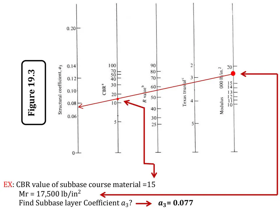
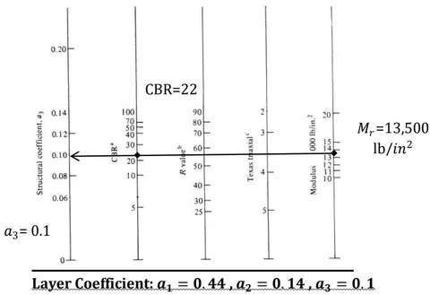
The quality of the material used is determined in terms of the layer coefficient (a3), which is used to convert the actual thickness of the subbase to an equivalent Structure Number (SN).
ii. Base Course Construction Materials
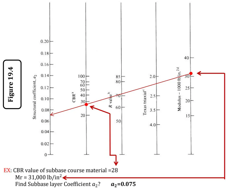
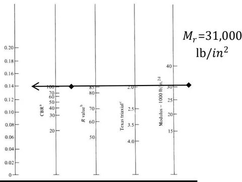
Materials selected should satisfy the general requirements for base course materials, A structural layer coefficient, a2, for the material used also should be determined.
iii. Surface Course Construction Materials
The structural layer coefficient (a1) relates to a dense graded asphalt concrete surface with its resilient modulus at .
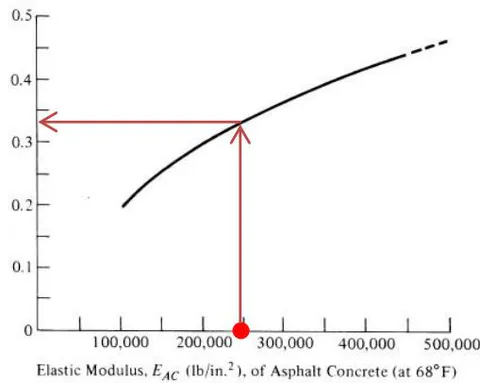
EX: Elastic Modulus of Asphalt Concrete Find Asphalt layer Coefficient ?
e) Environment
Temperature and rainfall are the two main environmental factors used in evaluating pavement performance in the AASHTO method.
The effects of temperature on asphalt pavements include stresses induced by thermal action and the impact of freezing and thawing water in the subgrade.
The effect of temperature, particularly about to the weakening of the underlying material during the thaw period, is considered a significant factor in determining the strength of the underlying materials used in the design. The effect of rainfall is due mainly to the penetration of the surface water into the underlying material, if penetration occurs, the properties of the underlying materials may be altered significantly.
The resilient modulus of materials susceptible to frost action can reduce by 50 percent to 80 percent during the thaw period, and it is likely that the strength of the material will be affected during the periods of heavy rains.
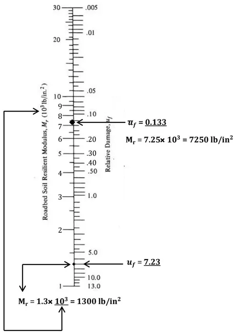
The AASHTO guide suggests a method for determining the effective, resilient modulus. In this method, a relationship is then used to determine the resilient modulus for each season based on the estimated in situ moisture content and Relative damage during the period of time.
The relative damage for each period is determined from the following chart, using the vertical scale or the equation given in the chart. The mean comparable damage then computed, and the effective subgrade resilient modulus is determined using the Chart and value of .

| Month | Roadbed Soil Modulus (lb/in.2) | Relative Damage |
| Jan. | 22000 | 0.01 |
| Feb. | 22000 | 0.01 |
| Mar. | 5500 | 0.25 |
| Apr. | 5000 | 0.30 |
| May | 5000 | 0.30 |
| June | 8000 | 0.11 |
| July | 8000 | 0.11 |
| Aug. | 8000 | 0.11 |
| Sept. | 8500 | 0.09 |
| Oct. | 8500 | 0.09 |
| Nov. | 6000 | 0.20 |
| Dec. | 22000 | 0.01 |
| Summation: | 1.59 | |
| Roadbed Soil Resilient Modulus, M1(103lb/in.2) | |
| .005 | |
| .01 | |
| .05 | |
| .10 | |
| .50 | |
| 1.0 | |
| 5.0 | |
| 10.0 | |
| 13.0 | |
Ex:
1- Find Roadbed Resilient Modulus When Relative Damage 7.23?
2- Find Roadbed Resilient Modulus For mean Relative damage ?
Using the Equation:
1- 0.723=1.18 × 10 × Solving →
2-Mean
-Using vertical scale:
f) Drainage.
The effect of drainage on the performance of flexible pavement is considered to the effect water has on the strength of the base material and roadbed soil, and The approach used is to provide for the rapid drainage of the water from the pavement structure by providing a suitable drainage layer and by modifying the structural layer coefficient.
The modification is carried out by adding a factor for the base and subbase layer coefficients and . The factors are based both on the percentage of time during which the pavement structure will be nearly saturated, and on the quality of drainage, which is dependent on the time it takes to drain the base layer to 50 percent of saturation.
Ex1:
A flexible pavement takes one day for water to be drained from within it and the pavement structure will be exposed to moisture levels approaching saturation for of the time. Find the pavement drainage coefficient?
Table 19.5: Definition of Drainage Quality
| Quality of Drainage | Water Removed Within* | ||
| Excellent 2 Good < | 2 hours 1 day < | ||
| 3 Fair Poor Very poor | 1 week 1 month (water will not drain) | ||
| Time required to drain the base layer to 7% saturation. | |||
| Table 19.6: Recommended m_i Values | |||
| Percent of Time Pavement Structure Is Exposed to Moisture Levels Approaching Saturation | 4 | ||
| Quality of Drainage | Less Than 1% | 1 to 5% | 5 to 25% Greater Than 25% |
| Excellent | 1.40-1.35 | 1.35-1.30 | 1.30-1.20 1.20 |
| Good | 1.35-1.25 | 1.25-1.15 | 1.15-1.00 1.00 |
| Fair | 1.25-1.15 | 1.15-1.05 | 1.00-0.80 0.80 |
| Poor | 1.15-1.05 | 1.05-0.80 | 0.80-0.60 0.60 |
| Very poor | 1.05-0.95 | 0.95-0.75 | 0.75-0.40 0.40 |
Pavement drainage coefficient
g) Reliability. R%
The cumulative ESAL is an essential input to any pavement design method. However, the determination of this input is usually based on assumed growth rates which may not be accurate.
AASHTO guide proposes the use of a reliability factor that considers the possible uncertainties in traffic prediction and pavement performance prediction.
For example, a reliability design level implies chance for successful pavement performance.
Table 19.7 shows suggested reliability levels based on the AASHTO guide.
Table 19.7: Suggested Levels of Reliability for Various Functional Classifications
| Recommended Level of Reliability | ||
| Functional Classification | Urban | Rural |
| Interstate and other freeways | 85–99.9 | 80–99.9 |
| Other principal arterials | 80–99 | 75–95 |
| Collectors | 80–95 | 75–95 |
| Local | 50–80 | 50–80 |
III. FLEXIBLE PAVEMENT STRUCTURAL DESIGN
drainage coefficient for the base, subbase layer layer coefficient of surface, base, and subbase Course
actual thickness in inches of the surface, base, and subbase courses
1-ByEquation
Where:
predicted number of 18,000-lb (80 KN) single-axle load applications
SN = structural number indicative of the total pavement thickness
standard normal deviation for a given reliability
overall standard deviation
Flexible pavements
Rigid pavements
Standard Deviation,
Table 19.8: Standard Normal Deviation Values Corresponding to Selected Levels of Reliability
| R% given → Reliability (R%) → Standard Normal Deviation, ZR | ||
| 1 | 50 | -0.000 |
| 60 | -0.253 | |
| 70 | -0.524 | |
| 75 | -0.674 | |
| 80 | -0.841 | |
| 85 | -1.037 | |
| 90 | -1.282 | |
| 91 | -1.340 | |
| 92 | -1.405 | |
| 93 | -1.476 | |
| 94 | -1.555 | |
| 95 | -1.645 | |
| 96 | -1.751 | |
| 97 | -1.881 | |
| 98 | -2.054 | |
| 99 | -2.327 | |
| 99.9 | -3.090 | |
| 99.99 | -3.750 | |
2-By Figure 19.8
Ex: Designing a Flexible Pavement Using the AASHTO Method
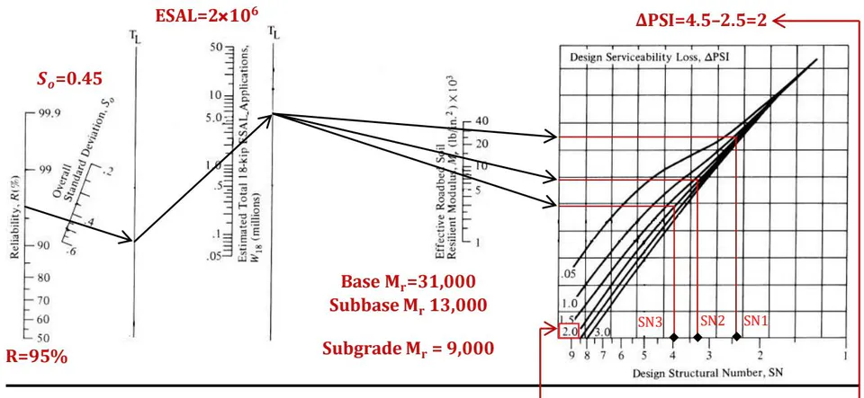
A flexible pavement for an urban interstate highway , and Standard deviation is to be designed to carry a design ESAL of . It is estimated that it takes about a week for the water to be drained from within the pavement, and the pavement structure will be exposed to moisture levels approaching saturation for of the time. The following additional information is available:
Initial serviceability index
Final serviceability index
Resilient modulus of asphalt concrete at
CBR value of base course material ,
CBR value of subbase course material ,
CBR value of subgrade material
Solution:
1- Find Drainage Coefficient from table 19.5, 19.6
Table 19.5: Definition of Drainage Quality
| Quality of Drainage | Water Removed Within* |
| Excellent | 2 hours |
| Good | 1 day |
| Fair | 1 week |
| Poor | 1 month |
| Very poor | (water will not drain) |
Table 19.6: Recommended Values
| Quality of Drainage | Percent of Time Pavement Structure Is Exposed to Moisture Levels Approaching Saturation | |||
| Less Than 1% | 1 to 5% | 5 to 25% | Greater Than 25% | |
| Excellent | 1.40-1.35 | 1.35-1.30 | 1.30-1.20 | 1.20 |
| Good | 1.35-1.25 | 1.25-1.15 | 1.15-1.00 | 1.00 |
| Fair | 1.25-1.15 | 1.15-1.05 | 1.00-0.80 | 0.80 |
| Poor | 1.15-1.05 | 1.05-0.80 | 0.80-0.60 | 0.60 |
| Very poor | 1.05-0.95 | 0.95-0.75 | 0.75-0.40 | 0.40 |
Drainage Coefficient for base and subbase layer = 0.8
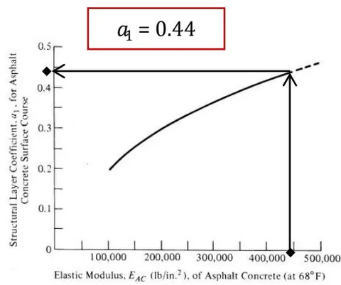
2- Find Layer Coefficient from figure 19.3, 19.4, 19.5
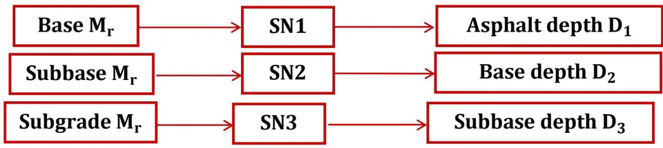
3- Find the Structure Number for each layer from figure 19.8
Principles of Pavement Design Yoder Ej (ch1,2,3).
Highway and Traffic Engineering N. Garber (ch19,20).