Joint Sequential use of the Reassigned Smoothed Pseudo Wigner-Ville Distribution and the Hough Transform vs. the Reassigned Smoothed Pseudo Wigner-Ville Distribution for Detecting and Characterizing Low Probability of Intercept Triangular Modulated Frequency Modulated Continuous Wave Radar Signals in Low Signal to Noise Ratio Environments
I. INTRODUCTION
The Low Probability of Intercept (LPI) signal used for this paper is the Frequency Modulated Continuous Wave (FMCW) signal, which is commonly used in modern radar systems [WAN10], [WON09], [WAJ08]. The frequency modulation spreads the transmitted energy over a large modulation bandwidth , providing good range resolution that is essential for discriminating targets from clutter. The power spectrum of the FMCW signal is nearly rectangular over the modulation bandwidth, so non-cooperative interception can be a challenge. Since the transmit waveform is deterministic, the form of the return signals can be predicted. This gives it the added advantage of being resistant to interference (such as jamming), since any signal not matching this form can be suppressed [WIL06]. Consequently, it is difficult for an intercept receiver to detect the FMCW waveform and measure the parameters accurately enough to match the jammer waveform to the radar waveform [PAC09].
The most prevalent linear modulation utilized is the triangular FMCW emitter [LIA09], since it can measure the target's range and Doppler [MIL02], [LIW08]. Triangular modulated FMCW is the waveform that is employed for this paper.
Time-frequency signal analysis involves the analysis and processing of signals with time-varying frequency content. These signals are best represented by a time-frequency distribution [PAP95], [HAN00], which shows how the energy of the signal is distributed over the two-dimensional time-frequency plane [WEI03], [LIX08], [OZD03]. Processing of the signal can exploit the features produced by the concentration of signal energy in two dimensions (time and frequency), instead of in one dimension (time or frequency) [BOA03], [LIY03]. Noise tends to spread out evenly over the time-frequency domain, whereas signals concentrate their energies within limited time intervals and frequency bands; therefore, the local SNR of a 'noisy' signal can be improved simply by using time-frequency analysis [XIA99]. In addition, the intercept receiver can increase its processing gain simply by implementing time-frequency signal analysis [GUL08].
Time-frequency representations are valuable for the visual interpretation of signal dynamics [RAN01]. An experienced operator can more easily detect a signal and extract the signal parameters by analyzing a time-frequency representation, vice a time representation, or a frequency representation [ANJ09].
One of the members of the time-frequency analysis techniques family is the Wigner-Ville Distribution (WVD). The WVD has several desirable mathematical properties: it is always real-valued, it preserves time and frequency shifts, and it satisfies marginal properties [QIA02]. The WVD is computed by correlating the signal with a time and frequency translated version of itself, making it bilinear. The WVD has the highest signal energy concentration in the time-frequency plane [WIL06]. By using the WVD, an intercept receiver can come close to having a processing gain near the LPI radar's matched filter processing gain [PAC09]. The WVD, however, contains cross term interference between each pair of signal components, which may limit its applications [GUL07], [STE96], and which can make the WVD time-frequency representation hard to read, especially if the components are numerous or close to each other, and the more so in the presence of The WVD of a signal is given in equation (1) as:
noise [BOA03]. This lack of readability may equate to less accurate signal detection and parameter extraction metrics, potentially placing the intercept receiver signal analyst's platform in harm's way.
or equivalently in equation (2) as:
A lack of readability must be overcome to obtain time-frequency distributions that can be easily read by operators and easily included in a signal processing application [BOA03].
Some efforts have been made recently in that direction, and in particular, a general methodology referred to as reassignment.
The original idea of reassignment was introduced to improve the Spectrogram [OZD03]. As with any other bilinear energy distribution, the Spectrogram is faced with an unavoidable trade-off between the reduction of misleading interference terms and a sharp localization of the signal components.
We can define the Spectrogram as a two-dimensional convolution of the WVD of the signal by the WVD of the analysis window, as in equation (3):
Therefore, the distribution reduces the interference terms of the signal's WVD, but at the expense of time and frequency localization. However, a closer look at equation (3) shows that delimits a time-frequency domain at the vicinity of the point, inside which a weighted average of the signal's WVD values is performed. The key point of the reassignment principle is that these values have no reason to be symmetrically distributed around , which is the geometrical center of this domain. Therefore, their average should not be assigned at this point, but rather at the center of gravity of this domain, which is much more representative of the local energy distribution of the signal [AUG94]. Reasoning with a mechanical analogy, the local energy distribution (as a function of and ) can be considered as a mass distribution, and it is much more accurate to assign the total mass (i.e. the Spectrogram value) to the center of gravity of the domain rather than to its geometrical center. Another way to look at it is this: the total mass of an object is assigned to its geometrical center, an arbitrary point which except in the very specific case of a homogeneous distribution, has no reason to suit the actual distribution. A much more meaningful choice is to assign the total mass of an object, as well as the Spectrogram value, to the center of gravity of their respective distribution [BOA03].
This is precisely how the reassignment method proceeds: it moves each value of the Spectrogram computed at any point to another point which is the center of gravity of the signal energy distribution around (see equations (4) and (5)) [LIX08]:
and thus, leads to a reassigned Spectrogram (equation (6)), whose value at any point is the sum of all the Spectrogram values reassigned to this point:
S_{x}^{(r)}\left(t^{\'},f^{\'};h\right) = \iint_{-\infty}^{+\infty} S_{x}\left(t,f;h\right)\delta\left(t^{\'}-\hat{t}\left(x;t,f\right)\right)\delta\left(f^{\'}-\hat{f}\left(x;t,f\right)\right)dt\,df\tag{6}One of the most interesting properties of this new distribution is that it also uses the phase information of the STFT, and not only its squared modulus as in the Spectrogram. It uses this information from the phase spectrum to sharpen the amplitude estimates in time and frequency. This can be seen from the following expressions of the reassignment operators:
where is the phase of the STFT of : . However, these expressions (equations (7) and (8)) do not lead to an efficient implementation, and must be replaced by equations (9) (local group delay) and (10) (local instantaneous frequency):
where and . This leads to an efficient implementation for the Reassigned Spectrogram without explicitly computing the partial derivatives of phase. The Reassigned Spectrogram may thus be computed by using 3 STFTs, each having a different window (the window function ; the same window with a weighted time ramp ; the derivative of the window function with respect to time (dh/dt)). Reassigned Spectrograms are therefore very computationally efficient to implement.
Since time-frequency reassignment is not a bilinear operation, it does not permit a stable reconstruction of the signal. In addition, once the phase information has been used to reassign the amplitude coefficients, it is no longer available for use in reconstruction. For this reason, the reassignment method has received limited attention from engineers, and its greatest potential seems to be where reconstruction is not necessary, that is, where signal analysis is an end unto itself.
One of the most important properties of the reassignment method is that the application of the reassignment process to any distribution of Cohen's class theoretically yields perfectly localized distributions for chirp signals, frequency tones, and impulses. This is one of the reasons that the reassignment method was chosen for this paper as a signal processing technique for analyzing LPI radar waveforms such as the triangular modulated FMCW waveforms (which can be viewed as back-to-back chirps).
To rectify the classical time-frequency analysis deficiency of cross-term interference, a method needs to be utilized that reduces cross-terms, which the reassignment method does.
The reassignment principle for the Spectrogram allows for a straight-forward extension of its use for other distributions as well [HIP00], including the WVD. If we consider the general expression of a distribution of the Cohen's class as a two-dimensional convolution of the WVD, as in equation (11):
replacing the particular smoothing kernel by an arbitrary kernel simply defines the reassignment of any member of Cohen's class (equations (12) through (14)):
The resulting reassigned distributions (which includes the Reassigned Smooth Pseudo Wigner-Ville Distribution (RSPWVD)) efficiently produce a reduction of the interference terms provided by a well-adapted smoothing kernel. In addition, the reassignment operators and are very computationally efficient [AUG95].
P.V.C. Hough patented the Hough transform in 1962 [HOU62], and it was later used in work accomplished by Duda and Hart [DUD72].
Consider the case where we have straight lines in an image. For every point in the image, all the straight lines pass through that point satisfy for varying values of line slope and intercept.
Now if we reverse our variables and look instead at the values of as a function of the image point coordinates , then becomes which also describes a straight line.
Consider two points and , which lie on the same line in the space. For each point, we can represent all possible lines through it by a single line in the space. Therefore, a line in the space that passes through both points must lie on the intersection of the two lines in the space representing the two points. This means that all points which lie on the same line in the space are represented by lines which all pass through a single point in the space.
To avoid the problem of infinite values which occurs when vertical lines exist in the image, an alternative formulation, (the parametric representation of a line) can be used to describe a line [CAR94], [DAH08]. This means that a point in the space (image space) is now
This can best be shown by Figure 1 below:
represented by a sinusoid in space (parameter space) rather than by a straight line. Points lying on the same line in the space define sinusoids in the parameter space which all intersect at the same point. The more points that exist on that particular line in image space; the more sinusoids will intercept at that particular point in parameter space, and consequently, the more the accumulator value at this point (parameter space) will increase, forming a 'spike' in the parameter space. Therefore, 'spikes' (peak values) in the parameter space correspond to lines in the image space. The coordinates of the point of intersection of the sinusoids in the parameter space define the parameters of the line in the space (image space). For example, if we apply the Hough transform to the WVD of a chirp (line), we obtain a peak in the parameter space located in a position which depends on the parameter values (such as chirp rate) of the chirp (line) in the image space (the WVD plot) [SHA07] [XUL93].
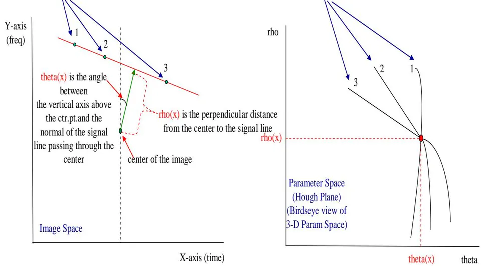
rho (x), theta (x) corresponds to the line connecting the points 1, 2, and 3 in the image space (same rho (x) and theta(x) values) [ISI96]. The more sinusoidal curves in the parameter space that pass through a particular point, the higher the accumulator value of that point will be and the higher the three-dimensional Hough Transform 'spike' will be [OLM01]. The presence of a peak in the parameter space reveals the presence of high positive values concentrated along a line in the image space - whose parameters are exactly the coordinates of the peak. The peak in the parameter space is located in a position which depends on the chirp rate of the line in the image space [BAR95]. The two-dimensional Hough transform plot is simply a birds-eye view of the three-dimensional plot, therefore a 'point' (or 'bright spot') in two-dimensional Hough transform plot is equivalent to a 'spike' in the three-dimensional Hough transform plot. The Hough transform converts a difficult global detection problem in the image space into a more easily solved local peak detection problem in the parameter space [THU04].
The Hough Transform of a given function is defined in equation (15) as:
Where is the Dirac delta function. With (as noted in the figure above), each point in the original image , is transformed into a sinusoid , where, in the image, is the perpendicular distance from the center of the image to the line at an angle from the vertical axis passing through the center of the image. Again, points that lie on the same line in the image will produce sinusoids that all cross at a single point in the Hough plot.
The expression above gives the projection (line integral) of along an arbitrary line in the x-y plane. By definition, the Hough Transform computes the integration of the values of an image over all its lines.
From the signal location (rho and theta values) of the Hough transform plot, it is possible to back-map back to the signal location in the time-frequency representation, using the same exact rho and theta values.
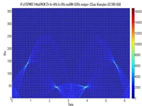
Let's give an example of back-mapping, starting with the Hough Transform plot in Figure 2:
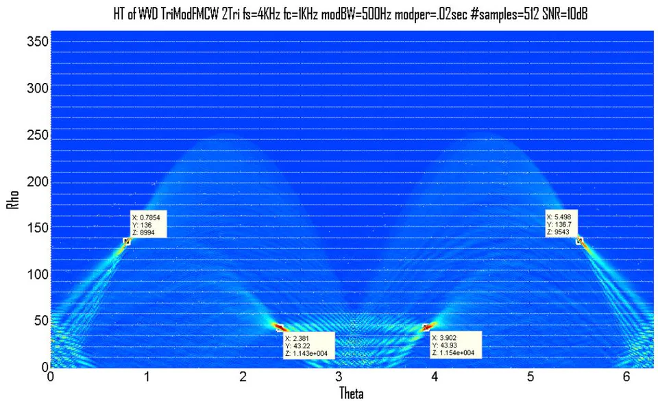
The values of rho and theta allow for back-mapping to the time-frequency distribution in order to determine the location of these 4 signals in the time-frequency distribution.
Theta is in radians, therefore we multiply by 57.3 to obtain degrees.
Rho is the number of samples, therefore we divide by 512 (the number of samples of the Y-Axis of the time-frequency distribution) to obtain rho (length) in terms of percent of the length of the entire Y-Axis of the time-frequency distribution.
Signal 1: 45.0 degrees, of Y-Axis
Signal 2: 136.4 degrees, of Y-Axis
Signal 3: 223.6 degrees, of Y-Axis
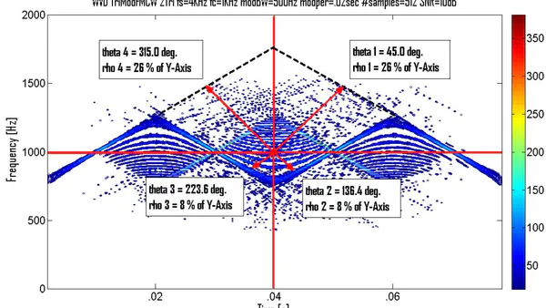
Signal 4: 315.0 degrees, of Y-Axis With these values, we can now back-map from the Hough transform plot (Figure 2) to the time-frequency distribution to find where the 4 signals are located in the time-frequency distribution (Figure 3).
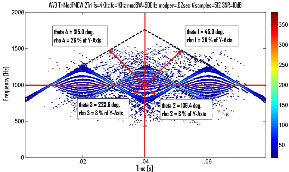
Figure 3 shows how the unique theta and rho values from the Hough transform plot can be used to back-map to the time-frequency distribution in order to find the location of the signals in the time-frequency distribution. This would be beneficial in the case where the signals in the time-frequency distribution were unable to be seen, due to cross-term interference and/or noise, but the signals were seen in the Hough transform plot. We could then back-map from the Hough transform plot, using the theta and rho values of the signals, to find the location of the signals in the time-frequency representation.
It is important to note that the Hough transform method works well in the presence of multi-component signals, in spite of the cross-terms produced by time-frequency distributions such as the WVD [TOR07]. Since the cross-terms have an amplitude modulation, the integration implicit in the Hough transform reduces them, while the useful contributions, which are always positive, are correctly integrated [BAR92], [BAR95]. Likewise, in the presence of noise, the integration carried out by the Hough transform produces an improvement in the SNR [INC07], [YAS06], [NIK08].
The Hough transform is very similar to the Radon transform. The Hough transform, like the Radon transform is a mapping from image space to parameter space. The Radon transform is usually treated as a reading paradigm (how a data point in the destination space is obtained from the data in the source space). The Hough transform is usually treated as a writing paradigm (how a data point in the source space maps onto data points in the destination space) [GIN04], [ZAl99].
Some additional advantages of the Hough transform are its ability to discard features belonging to other objects and its robustness against incomplete data [CAR06], [BEN05].
The Hough transform finds many uses today, from signal processing (such as low SNR signal extraction and chirp rate determination) to image processing (such as locating iris features in frontal face images [TOE02]).
The ability of the Hough Transform to perform well in low SNR environments, as well as in heavy cros-term environments makes it an ideal signal analysis tool to offset the classical time-frequency analysis deficiencies of cross-term interference and mediocre performance in low SNR environments. This makes for better readability, leading to more accurate parameter extractions for the intercept receiver signal analyst.
The joint sequential use of the RSPWVD and the Hough Transform (HT) will be used in this paper.
II. METHODOLOGY
The methodologies detailed in this section describe the processes involved in obtaining and comparing metrics between the joint sequential use of the Reassigned Smoothed Pseudo Wigner-Ville Distribution and the Hough Transform vs. the Reassigned Smoothed Pseudo Wigner-Ville Distribution signal processing techniques for the detection and characterization of low probability of intercept triangular modulated FMCW radar signals.
The tools used for this testing were: MATLAB (version 8.3), Signal Processing Toolbox (version 6.21), and Time-Frequency Toolbox (version 1.0) (http://tfdb.nongnu.org/).
All testing was accomplished on a desktop computer (Dell Precision T1700; Processor -Intel Xeon CPU E3-1226 v3 3.30GHz; Installed RAM - 32.0GB; System type - 64-bit operating system, x64-based processor).
Testing was performed for the triangular modulated FMCW waveform, whose parameters were chosen for academic validation of signal processing techniques. Due to computer processing resources they were not meant to represent real-world values. The number of samples was chosen to be 512, which seemed to be optimum size for the desktop computer. Testing was performed at three different SNR levels: 10dB, 0dB, and the lowest SNR at which the signal could be detected. The noise added was white Gaussian noise, which best reflects the thermal noise present in the IF section of an intercept receiver
[PAC09]. Kaiser windowing was used, where windowing was applicable. 100 runs were performed for each test, for statistical purposes. The plots included in this paper were done at a threshold of of the maximum intensity and were linear scale (not dB) of analytic (complex) signals; the color bar represented intensity. The signal processing techniques used for each task were the joint sequential use of the Reassigned Smoothed Pseudo Wigner-Ville Distribution and the Hough Transform vs. the Reassigned Smoothed Pseudo Wigner-Ville Distribution.
The triangular modulated FMCW signal (most prevalent LPI radar waveform [LIA09]) used had the following parameters: sampling frequency ; carrier frequency ; modulation bandwidth ; modulation period .
After each individual run for each individual test, metrics were extracted from the time-frequency representation. The metrics that were extracted were as follows:
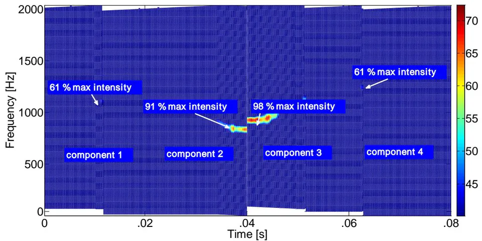
- Percent Detection: The percent of time signal was detected - signal was declared a detection if any portion of each of the signal components(4 chirp components for triangular modulated FMCW)exceeded a set threshold (a certain percentage of the maximum intensity of the time-frequency representation).
Threshold percentages were determined based on visual detections of low SNR signals (lowest SNR at which the signal could be visually detected in the time-frequency representation) (see Figure 4).
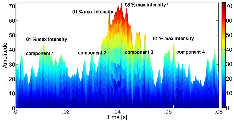


Based on the above methodology, thresholds were assigned as follows for the signal processing techniques used for this paper: RSPWVD + HT (60%); RSPWVD (60%).
For percent detection determination, these threshold values were included for each of the signal processing technique algorithms so that the thresholds could be applied automatically during the plotting process. From the time-frequency representation threshold plot, the signal was declared a detection if any portion of each of the signal components was visible (see Figure 5).
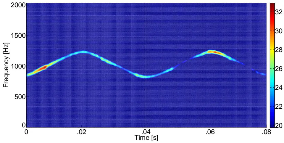
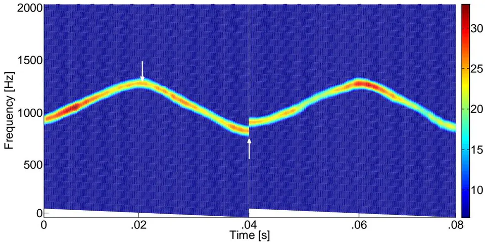
- Modulation Bandwidth (Note: Modulation bandwidth was used to calculate the Chirp Rate): The distance from the highest frequency value of signal(at a threshold of maximum intensity)to the lowest frequency value of signal (at same threshold) in Y-direction (frequency).
The threshold percentage was determined based on manual measurement of the modulation bandwidth of the signal in the time-frequency representation. This was accomplished for ten test runs for each of the signal processing techniques that were used, for the triangular modulated FMCW waveform. During each manual measurement, the max intensity of the high and low measuring points was recorded. The average of the max intensity values for these test runs was . This was adopted as the threshold value and is representative of what is obtained when performing manual measurements. This threshold was also adapted for determining the modulation period and the time-frequency localization (both are described below).
For modulation bandwidth determination, the threshold value was included for each the signal processing technique algorithms so that the threshold could be applied automatically during the plotting process. From the threshold plot, the modulation bandwidth was manually measured (see Figure 6).
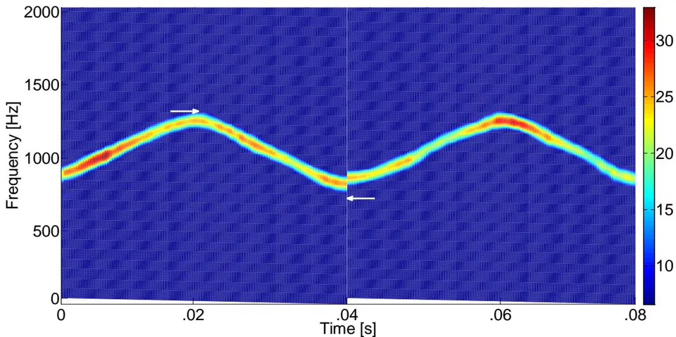
- Modulation Period (Note: Modulation period was used to calculate the Chirp Rate): The distance from the highest frequency value of signal(at a threshold of maximum intensity)to the lowest frequency value of signal (at same threshold) in X-direction (time).
For modulation period determination, the threshold value was included for each of the signal processing technique algorithms so that the threshold could be applied automatically during the plotting process. From the threshold plot, the modulation period was manually measured (see Figure 7).
- Chirp Rate: Equals (modulation bandwidth)/ (modulation period)
- Lowest Detectable SNR: The lowest SNR level at which at least a portion of each of the signal components exceeded the set threshold listed in the percent detection section above.
For lowest detectable SNR determination, these threshold values were included for each of the signal processing technique algorithms so that the thresholds could be applied automatically during the plotting process. From the threshold plot, the signal was declared a detection if any portion of each of the signal components was visible. The lowest SNR level for which the signal was declared a detection is the lowest detectable SNR (see Figure 8).
The data from all 100 runs for each test was used to produce the actual, error, and percent error for each of the metrics listed above.
The metrics for the joint sequential use of the Reassigned Smoothed Pseudo Wigner-Ville Distribution and the Hough Transform, along with the metrics for the Reassigned Smoothed Pseudo Wigner-Ville Distribution were generated. By and large, the joint sequential use of the Reassigned Smoothed Pseudo Wigner-Ville Distribution and the Hough Transform (RSPWVD + HT) outperformed the Reassigned Smoothed Pseudo
Wigner-Ville Distribution (RSPWVD), as will be shown in the results section.
III. RESULTS
Table 1 presents the overall test metrics for the two signal processing techniques used for this testing (the joint sequential use of the Reassigned Smoothed Pseudo Wigner-Ville Distribution and the Hough Transform (RSPWVD + HT) versus the Reassigned Smoothed Pseudo Wigner-Ville Distribution (RSPWVD)).
| Parameters | RSPWVD + HT | RSPWVD | ||||
| 10dB | 0dB | -3dB | 10dB | 0dB | -3dB | |
| Chirp Rate (avg.% error) | 0.41% | 0.51% | 0.68% | 1.58% | 2.81% | 5.74% |
| Percent Detection (avg.) | 100% | 100% | 72.8% | 100% | 92.4% | 8.21% |
| Lowest Detectable SNR (avg.) | [-5.04db] | [-3.02db] | ||||
From Table 1, RSPWVD + HT outperformed RSPWVD in average percent error chirp rate (10dB: 0.41% vs. 1.58%), (0dB: 0.51% vs. 2.81%), and (-3dB: 0.68% vs. 5.74%). RSPWVD + HT outperformed RSPWVD in average percent detection (10dB: 100% vs. 100%), (0dB: 100% vs. 92.4%), and (-3dB: 72.8% vs. 8.21%). RSPWVD + HT outperformed RSPWVD in average lowest detectable SNR (-5.04dB vs. -3.02dB).
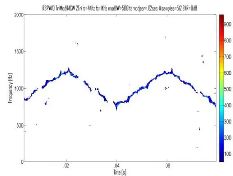
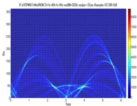
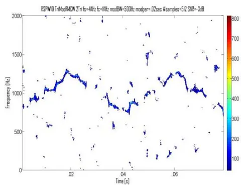
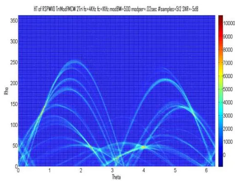
Figure 9 shows comparative plots of the RSPWVD (left) vs. the RSPWVD + HT (right) (triangular modulated FMCW signal) at SNRs of 10dB (top row), 0dB (middle row), and lowest detectable SNR (-3dB for RSPWVD and -5dB for RSPWVD + HT) (bottom row).

IV. DISCUSSION
This section will elaborate on the results from the previous section.
From Table 1, RSPWVD + HT outperformed RSPWVD in average percent error chirp rate (10dB: 0.41% vs. 1.58%), (0dB: 0.51% vs. 2.81%), and (-3dB:
0.68% vs. 5.74%). RSPWVD + HT outperformed RSPWVD in average percent detection (10dB: 100% vs. 100%), (0dB: 100% vs. 92.4%), and (-3dB: 72.8% vs. 8.21%). RSPWVD + HT outperformed RSPWVD in average lowest detectable SNR (-5.04dB vs. -3.02dB).
In previous research it was shown that the reassignment method, with its squeezing and smoothing qualities, reduces cross-term interference of classical time-frequency distributions (i.e. WVD), and produces more localized ('tighter') signals than those of the classical time-frequency distributions, making for improved readability, and consequently the extraction of more accurate metrics than the classical time-frequency distributions [STE21].
In the presence of noise, the integration carried out by the Hough transform produces an improvement in SNR [INC07], [YAS06], [NIK08], and therefore the Hough transform is better able to 'dig' the signal out of noise. This robust performance in low SNR environments translates to improved readability of the Hough Transform plot, and consequently more accurate signal detection and parameter extraction of LPI radar signals.
For the RSPWVD + HT combination, the squeezing quality of the reassignment method, combined with the integration carried out by the Hough transform, makes for 'tighter' signals (equals more accurate theta value extraction and therefore more accurate chirp rate extraction (than for the RSPWVD alone), as per the results in Table 1), and makes for 'higher' signals (equals detecting the signal at lower SNR values (than for the RSPWVD alone), as per the results in Table 1), and better percent detection (than for the RSPWVD alone) due to the signal being that much higher than the noise floor, as per the results in Table 1). Therefore the joint sequential use of the RSPWVD and the HT allows for more accurate signal detection and parameter extraction of LPI radar signals than the RSPWVD alone, making for a more informed, effective, and safer intercept receiver environment, potentially saving valuable equipment, intelligence, and lives.
V. CONCLUSIONS
Digital intercept receivers, whose main job is to detect and extract parameters from low probability of intercept radar signals, are currently moving away from Fourier-based analysis and towards classical time-frequency analysis techniques (such as the WVD), and other novel analysis techniques. Though classical time-frequency analysis techniques are an improvement over Fourier-based analysis techniques, classical time-frequency analysis techniques, in particular the WVD, suffer from cross-term interference, which can make the time-frequency representation hard to read, especially if the components are numerous or close to each other, and the more so in the presence of noise. This lack of readability may equate to less accurate signal detection and parameter extraction metrics, potentially placing the intercept receiver signal analyst's platform in harm's way.
In previous research it was shown that the reassignment method, with its squeezing and smoothing qualities, reduces cross-term interference of classical time-frequency distributions (i.e. WVD), and produces more localized ('tighter') signals than those of the classical time-frequency distributions, making for improved readability, and consequently the extraction of more accurate metrics than the classical time-frequency distributions [STE21].
The research in this paper demonstrated that through the joint sequential use of the RSPWVD and the Hough Transform, the squeezing quality of the reassignment method, combined with the integration carried out by the Hough transform, made for 'tighter' signals (equals more accurate theta value extraction and therefore more accurate chirp rate extraction (than for the RSPWVD alone), as per the results in Table 1), and made for 'higher' signals (equals detecting the signal at lower SNR values (than for the RSPWVD alone), as per the results in Table 1), and better percent detection (than for the RSPWVD alone) due to the signal being that much higher than the noise floor, as per the results in Table 1). Therefore the joint sequential use of the RSPWVD and the Hough Transform allows for more accurate signal detection and parameter extraction of LPI radar signals than the RSPWVD alone, making for a more informed, effective, and safer intercept receiver environment, potentially saving valuable equipment, intelligence, and lives.
Future plans include continuing to analyze low probability of intercept radar waveforms (such as the frequency hopping and the triangular modulated FMCW), using additional novel signal processing techniques, and comparing their results with research that has been conducted.