The measurement of a mechanical impulse of the plasma thruster has been performed using by the well-known magnetoplasma compressor assembly (MPC) and features of the convergence nozzle. Based on previous research [6], hydrogen had selected as a working gas, from the reason that it can produce the highest velocity of plasma. Because of the magneto hydrodynamics model (MHD), it is entirely possible to perform rules for fluid dynamics to electromagnetism, with appropriate analog. Using all the mentioned tools, it can be determined limit value for plasma speed like analogue to sound speed, and according to, define the value of the analog Mach number for plasma. Such that would have far-reaching consequences because it would greatly facilitate feature research and the construction of plasma thrusters. Occurrence of velocity saturation indicates congestion of the nozzle, which arises as a consequence of the convergence of the nozzle, and this saturation is the velocity value corresponding to the limiting speed of plasma at a current circumstance. As the result is in agreement with the initial hypothesis, and the dependence is also confirmed with the derived formula, we can conclude that exists uniform relation between occurrences; also this occurrence are universal law of nature. Also, it is necessary to emphasize the importance of finding formula for the velocity field, which have been proved by numerical methods.
## I. INTRODUCTION
There is two types of object motion, when the distance between particles doesn't change, and move, when the distance between particles varies. Objects where the distance between the particles can vary are fluids or elastic objects. Fluids are objects that has no fixed shape, sometimes neither volume, because particles that make them can move freely, constantly changing their mutual distance. [1] Properties of fluid are strictly determined by the properties of the particles from which they are made, such as size, mobility, charge, etc. [2]
If considering a fluid low mobility of charge carriers, that means with low conductivity, and now start to energize this fluid. The mobility of charge carriers is rising, and as a consequence rise level of conductivity, the energy gap is shrinking more and more until this fluid becomes a conductor. [3] From the other side, energized fluid particles become faster, and therefore the velocity of fluid rises. If we continue to bring energy to fluid, and now we can initiate the movement of ions, and now this fluid we call "plasma" we can consider that plasma is fluid with the ability of good conductivity. Plasma presents ionized gas, which consists of ions, atoms that are separate with their orbital electrons, and free electrons. [2] [4]
The following is necessary to connect fluid dynamics and plasma dynamics; it is most suitable to do it through equations. It can be achieved by combining continuity equations, Maxwell equations, and Navier-Stokes equations. The model that connects these equations and rules is the Magnetic Hydrodynamics plasma model (MHD), and the submodel in MHD responsible for plasma propulsion is the Magnetic Hydrodynamics accelerator. [3]
Magneto hydrodynamics is a model of electrically conducting fluids that treat all interpenetrating particle species together as a single continuous medium. It is primarily concerns with the low-frequency magnetic behavior in plasmas and liquid metals. [5] A partially ionized gas is a three-component mixture of electrons, ions, and neutral particles. Its behavior in a field can be described in terms of the ordinary equations of gas dynamics. We will consider here a simplified and more frequently used, for discharge condition, version of equations, assuming the gas to be at rest as a whole, weakly ionized, and quasineutral. It is sufficient to write the equations only for the electron gas. Its state is characterized by the charge density, the vector of macroscopic velocity, temperature, or pressure. [3].
According to research performed during 2019 and 2020 year in the laboratory of the Physics Faculty, Belgrade University, we find that plasma propulsion is possible to generate using a magnetoplasma compressor (MPC). Then we only performed an assay, using a ballistic pendulum in order to prove that propulsion is possible, and the result was enchanting. The plasma beam from the MPC was so intense that the probe plate was broken into several pieces and scattered inside the chamber. This scene also envisages difficult conditions for designing an experiment, that is, performing specific measurements.
To determine parameters for a plasma propulsor, it is necessary to know specific properties, such as the field of velocity, temperature distribution, and mass flow. A fluid is observed as a mixture of particles with different properties, such as mass, velocity, size, etc. - so the mass flow isn't constant. In the beginning, we can determine the velocity of the plasma, using the Rogovski coil, and roughly determine that the temperature is of the order of magnitude $\sim 10^{4}^{\circ}K$. [6] This means that we are working with a complex fluid, without the possibility to measure any physics quantity, except velocity directly.
A Rogowski coil is an electrical device for measuring alternating current or high-speed current pulses; it registers particle drift relative to the primary direction. It sometimes consists of a helical coil of wire with the lead from one end returning through the center of the ring to the other end so that both terminals are at the same end of the coil. Since the voltage that is induced in the coil is proportional to the rate of change (derivative) of current in the straight conductor, the output of the Rogowski coil is a change in the number of particles through the contour, and that ultimately gives flow rate - velocity. [7] In such situations, when the conditions for measurements are non-exceeding, and mass flow is unsteady, we can perform a rule for a boost of convergence nozzle, the relation between the flow coefficient and Reynolds number. Convergence nozzle has the property that it cannot produce supersonic flow, i.e., it gives a maximum Mach number of approximately one ( $M = 0.99999$ ). For values of Mach number close to one, the ratio between the flow coefficient and Reynolds number is constant, which will ultimately mean that the mass flow is continuous in such a flow. [8] [9] In the further part of the text, the theoretical and experimental settings, the derivation of the formulas, and the result will be presented, with a discussion related to the derived formulas.
## II. EXPERIMENTAL SETUP AND EQUIPMENT PROPERTIES
The experiment is carried out using a plasma accelerator, which is placed inside a steel chamber in which there is a vacuum, there no heavy particles. The plasma accelerator is an assembly in the center of which a cathode is placed, around which eight-rod anodes are arranged concentrically. The electrodes (cathode and anode) are made of copper, solid material, so the cathode is $5 \, \text{cm}$ long with, $3 \, \text{cm}$ radius, while the anodes are $14 \, \text{cm}$ long, with and $0.8 \, \text{cm}$ radius. [6]
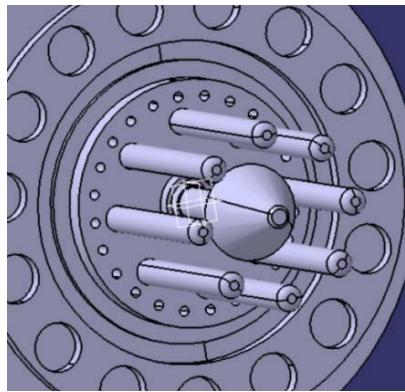 Figure 1: Model of the used equipment, built in the program CATIA V5
The equipment consists of a high-voltage generator from $1kV$ to $5kV$ and a high current of up to $5000A$, intended for powering a plasma accelerator or a magnetic plasma compressor (MPC). Inside the generator, there is a system for the periodic discharge of particles of the working gas, coordinated with the voltage pulse that is transmitted to the electrodes. There is a high-capacity capacitor in series with the source, which has the role of providing a pulse signal to the accelerator. A Rogowski coil is attached to the back of the accelerator, which protrudes from the steel chamber. Opposite the plasma accelerator is another Rogowski coil; with cooperation with the first coil, we can determine the speed of the plasma. The Rogowski coils are connected to an oscilloscope whose role is to register the recorded signals and, based on the comparison of those signals provide information on the plasma velocity distribution. [10]
The Rogowski coil usually consists of a torus coil with a large number of windings; the density of the winding, the diameter of the winding, and the stiffness of the windings are circular for maintaining resistance to external fields and a low sensitivity limit. For this case and similar cases, it is particularly suitable to use the torus geometry for the Rogowski coil, because it works with very high voltages and high currents. Toroidal geometry has the advantage of central excitation, which doesn't excite standing waves in the coil, thus reducing the probability of resonance. Standing waves and resonance, in this case, are harmful, because they can cause the coil to oscillate constantly, an excitation that takes a long time to stop; this can also cause the Rogowski coil to malfunction. [7] As the voltage induced in the coil is proportion to the rate of change of the current in the plasma jet, the output of the Rogowski coil is most often connected to an electrical integrated circuit, an amplifier circuit, and a stabilizer circuit, to obtain an output signal that is proportional to the current. The voltage induced in the Rogowski coil, based on the dependencies mentioned in the previous text, can be expressed by the formula: [6] [10]
$$
U (t) = - \frac {A N \mu_ {0}}{l} \frac {d I (t)}{d t}, \qquad A = r ^ {2} \pi , \qquad l = 2 \pi R
$$
where $A$ represents the inside surface of the coil, $N$ is the number of coil windings, $l$ is the circumference of the coil's outer ring, $\frac{dI(t)}{dt}$ the level of charge in the strength of the electric current along the surface.
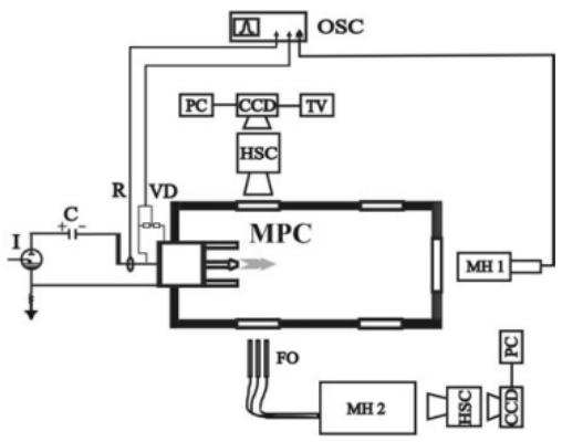 [6] Figure 2: Experimental setup: C—capacitor, I—ignitron, OSC—oscilloscope for registration of signals from Rogowski coil (R), voltage divider (VD) and McPherson spectrometer (MH1), HSC—high-speed camera, FO—fiber optics, MH2—Jobin Yvon spectrometer
The anode, in this case, is not designed from one part, like a ring, but is intended as an assembly, which consists of 8 copper rods that are arranged concentrically around the cathode. The reason for this is the fact that the group of anodes and cathodes endure very high temperatures, over $20000^{\circ}K$, which occurs as a result of the high current from the generator. In these conditions, the electrodes suffer a high degree of erosion, and copper wear occurs; if rod anodes are used instead of ring anodes, erosion on the anodes is almost completely neutralized. Ions are introduced into the accelerator through rod anodes, between which rods a "wiped" current is formed in a vacuum. The gas around the anode acts as a virtual electrode, and its magnetic field protects the rod anodes from erosion. [6] [11]
Reduction of erosion is a multiple gain, in addition to reducing wear of electrodes, providing them with a longer lifespan, and reducing impurities in the plasma, which shows better performance than plasma with copper impurities. [11] On the support, between the anode and the cathode, there are working gas injectors, through which the working gas is released into the high-voltage environment that, at the moment, regains between the anode and the cathode, energizing that working gas, igniting it, the accelerator fires a plasma pulse. The working gas injectors are specially shaped and placed in an optimal position, concerning the anode and cathode, to prevent a possible breakdown of the discharge on the surface of the injectors, i.e., the support. [6]
This further enables high injection quality, which leads to the necessary stability of the ionization zone, avoiding measurement of the plasma jet according to the output of the working gas. The stability of the compression of the plasma jet flow is manifested by a symmetrical and homogeneous cylindrical discharge of the current propagated through the surface of the electrodes. The symmetry of the discharge is recorded as a specific section of the formation composed of energy storage cells according to the sphere and continuous input of the working gas through the electrodes. [10]
## III. EXPERIMENT DESCRIPTION
Plasma is observed as a gas that doesn't have a constant mass flow and consists of charged particles, so it is subject to the laws of fluid mechanics and electromagnetism simultaneously. As already mentioned, the environment is vary unfavorable for measurement, in general, for conducting an experiment; therefore, we cannot work with a continuous stream of the plasma, because, in that way, we would endanger the apparatus, so the plasma must work in pulse mode. Also, because the principle of a convergent jet describes the change in speed concerning the difference in the area of the output cross-section, it is necessary to perform more measurements for the different distance between anodes rod, which can show the dependence of the output speed on the cross-sectional area. Several positions are provided on the support for each anode, so we get several exit cross-sectional surfaces. In this way, we simulate the narrowing of the cross-sectional surface of the convergent nozzle. In order for the experiment to show a positive result, it is necessary to demonstrate convergence velocity with a decrease in the distance between the anode rods, which should ultimately lead to velocity saturation. Velocity saturation, in this case, should represent jet congestion i.e., reaching the maximum Mach number for a convergent jet, which is approximately one. Based on the relation between the flow coefficient and the Reynolds number [8], in this case, magnetic Reynolds number, the mass flow can be considered constant.
The magnetic Reynolds number represents a quantity analogous to the ordinary Reynolds number. Unlike the Reynolds number, which means the ratio of inertial force and viscous force, the magnetic Reynolds number represents the ratio of the conventional $\left| \text{curl}(\vec{v} \times \vec{B}) \right|$ and diffusion $\left| v_m \Delta \vec{B} \right|$ factor in plasma. So we get an expression for the magnetic Reynolds number as: [3]
$$
\frac {\left| c u r l (\vec {v} \times \vec {B}) \right|}{\left| v _ {m} \Delta \vec {B} \right|} \approx \frac {\frac {1}{D} V B}{v _ {m} \frac {1}{D ^ {2}} B} = \frac {D V}{v _ {m}} = R e _ {m}
$$
where $D$ is the characteristic dimension of the system, $V$ is the characteristic velocity of motion (flow), and $v_{m}$ is the speed of movement of charge carried in a magnetic field. Based on the Helmholtz equation, we observe that this equation measures the relative influence of the conventional and diffusion terms in the equation for the time evolution of the vorticity vector $\vec{\omega} = \frac{1}{2} \text{curl} \vec{v}$. [3] On the support, it is possible to place rod anodes in the form of a concentric circle concerning the cathode in the center, with different radius values, without the residual harmful effects of one set compared to the other. This is important to note because one can get the impression that always the same positioned injector of the working gas can affect the results of the experiment, which is not the case here. The working gas injector is set to be most optimal for the most challenging case, the point when the distance between the anode and the cathode is minimal; the occurrence of anomalies such as the breakdown of the discharge on the surface of the injection of the working gas or the shift of the working gas or plasma towards the source can be fatal. In other cases, the working gas injector is further away from the anode, and the distance is greater than optimal; instead of the optimal, the term minimum is more suitable, because the primary spark starts from the anode.
When energizing the electrodes, to ignite the working gas, i.e., creating plasma, a magnetic field appears around the electrodes. As a consequence of the mutual action of magnetic fields that arise due to the flow of current through the anode and cathode, a concave magnetic lens is created, conditionally speaking, which collides with the plasma beam. As the anodes are closer to the cathode, the magnetic lens will be more robust, i.e., the more it compresses the plasma, which is analogous to the reduction of the exit cross-section area of the convergent nozzle. On the contrary, the farther the electrodes are, the magnetic leans that they bind is weaker, i.e., analogous to the increase in the outer cross-sectional area of the converging nozzle.
We will not go to the congestion of the converging nozzle experimentally. Still based on the several obtained values and using the appropriate form of extrapolation, the idea is to graphically arrive at the value at which the nozzle is congested. The reason for this is the high safety risk we are exposed to when the nozzle is clogged.
The complete experiment will be repeated several more times, at the same value of pressure, about $1000 \, \text{Pa}$, because according to previous research
[6], due to a reduction of pressure below $1000\mathrm{Pa}$ there is an increased erosion of the cathode, which leads to a decrease in the velocity of plasma steam. This decrease in velocity is explained as a consequence of the impurity of the working gas in the plasma nozzle, which causes an increase in the mass of the working gas. Also, based on previous experiments [6] it was shown that hydrogen as a working gas can achieve the highest plasma output velocity, so that we will use hydrogen as a working gas.
### a) Initial conditions and assumptions
The calculation of the specific thrust, that is, the mechanical impulse or any parameter that has a role to describe and explain the plasma as a propellant will be following the rocket engine. So, we look at the plasma thruster as a rocket engine and expect the plasma thruster equation to confirm the rocket engine equations, or at least the form of the thrust equation: $\vec{F}_P = \dot{m}_{ps}\vec{v}_i$. This idea is self-evident, because the plasma thruster, like the rocket engine, has no inlet, in the sense that there is no inlet mass flow of gas, but it is a consequence of the process that takes place inside the thruster itself.
The basic assumption is that due to the reduction of the outer cross-section of the nozzle, velocity saturation occurs, i.e., the appearance of a limiting velocity analogous to the ejection of air from the convergent nozzle.
Due to the excessive energies that will be developed during the performance of the experiment, the action of the high voltage and a very strong current, and due to the act of the very strong magnetic field, at the moment when the electrodes are very close, erosion of the cathode can be caused. This erosion will occur as a result of excess energy, will cause a decrease in velocity, and can be considered analogous to the congestion of the converging nozzle.
## IV. EXPERIMENTAL RESULTS
The experiment was carried out in the summer, of July 2020. The operating temperature was $27^{\circ}\mathrm{C} \left(\sim 300^{\circ}\mathrm{K}\right)$, with a relative humidity of about $45\%$, while the atmospheric pressure was 993 mbar and the altitude was $110m$. Based on the initial conditions of the experiment, we get that the speed of sound is
$$
c = \sqrt{\frac{kRT_0}{M}} = 347 \frac{m}{s}.
$$
Based on the course of the experiment, the discharge time, that is, the duration of the plasma pulse, was recorded to be about $8\mu s$, and it doesn't change much with the charge of operating conditions. The deviations are about $\pm 2\mu s$. The only change that has a severe effect on discharge time is changing the working gas. However, the discharge time doesn't exceed $20\mu s$, which is a very short time to measure anything on that pulse, especially not the flow rate distribution of the generated plasma.
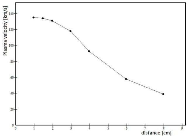 Figure 3: Plasma flow velocity for hydrogen $(\mathsf{H}_2)$ in the function of the distance between cathode and anodes, under the constant pressure $P = 1000Pa$
With the help of Rogowski's coil measured values, we obtained very high mean plasma velocities (Figure 3.) of the order of $\sim 10^{2} \frac{km}{s}$, which will be shown in more detail later in the text, as well as the occurrence of convergence. As the velocity of the plasma steam increase, so does the heat radiated by the plasma. Regarding the heat, it is important to note that at a distance of $5cm - 7cm$ from the plasma nozzle outer, the plasma steam reaches its maximum in terms of energy, therefore the heat it radiates.
During the experiment, the zones responsible for the parameters of the plasma beam could be observed, ionization zone and compression zone.
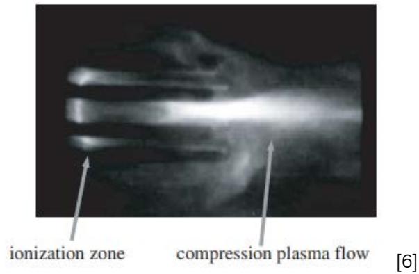 Figure 4: Plasma discharge, represented with ionization zone and compression plasma flow zone
After energizing the electrodes with a voltage of $\sim 10^{3}kV$, gas is automatically released into the ionization zone, which triggers the ignition of the plasma accelerator. The start of the plasma accelerator discharge depends on the pressure of the working gas, and accordingly, it can start from the place where the distance between the anode and the cathode is the smallest.
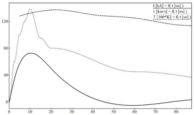 Figure 5: Distribution of electric current $I[kA]$, plasma velocity $v\left[\frac{km}{s}\right]$ and plasma temperature $T[100 \cdot K]$ in the function of time interval $t[\mu s]$
During discharge, the discharge current and magnetic field increase. The actual discharge begins at the movement when the electric filed is established within the entire volume through which the plasma steam will spread. Compression occurs under the influence of a magnetic field, which means that the magnetic field simulates the convergence of the nozzle. The increase of the magnetic field, i.e., the transfer of almost complete energy is established only at the entrance to the acceleration channel.
Further, the plasma formed in this way is compacted, and compressed, under the effect of the magnetic field that arises as a result of the flow of current through the electrodes. The plasma steam is compressed due to the interaction between the longitudinal component of the current caused by the discharge and the azimuthal magnetic field, as well as due to the dynamic pressure of the plasma steam converging towards the abscissa of the system. [4]
## V. NUMERICAL SOLUTION, EQUATION OF CONVERGENCE NOZZLE
The Numerical calculation was performed in COMSOL Multiphysics, using the custom method DC discharge, described by the Navier-Stokes equation adjusted to electrodynamics. In this way, we could roughly confirm the experimental results, neglecting the numbers themselves, but paying attention to the occurrence of velocity saturation. The velocity saturation would unquestionably prove the validity of the convergent nozzle law in plasma propulsors. Nevertheless, even though we would obtain solutions for the ideal case, the numerical method is beneficial for finding the velocity field of plasma steam.
Due to the symmetry of the apparatus, we can consider that the two-dimensional system can adequately describe the situation. This approximation should not significantly affect on the velocity and magnetic field vector, i.e., the resulting velocity field should not deviate significantly from the real one.
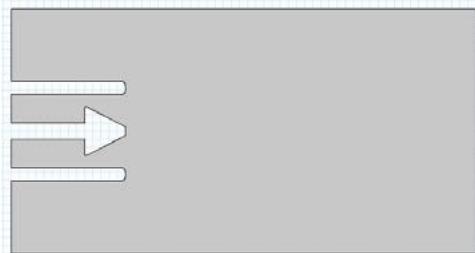 Figure 6: Model of Magneto Plasma Compressor for Numerical Method
For the description of fluid motion, some radical changes will have to be made to the standard equations of motion given in the program. The properties of working gas, and chemical reaction, will be used from the program's database, file (H_xsecs), for hydrogen $\mathsf{H}_2$. [14] The significant factor for proper description of plasma flow is the existence of diffusion, i.e., ambipolar diffusion $D_{a} = \frac{D_{+}\mu_{-} + D_{-}\mu_{+}}{\mu_{-} + \mu_{+}}$; [4] ambipolar diffusion is included in the equation of motion with a vector of current density $\vec{j}$. The diffusion model will be the mixture-average model, which includes the migration of charged particles in the electric field, and plasma purpose - reduction of electrons during transportation properties. Although a DC discharge ultimately reaches a steady-state condition, the problem must be solved as a time-dependent problem so the plasma can naturally evolve into its equilibrium state. [14] In purpose to import the influence of the magnetic field, as a crucial factor in this research, we will use AC/DC interfaces – electric current interfaces. As the magnetic field itself has no role other than plasma compression, i.e., the simulation of the convergent nozzle, the evolution of this physics quantity doesn't
reflect in results, so we will assume that the magnetic field is stationary. [15]
# a) The
To purposely numerically describe plasma propulsion, it is necessary to start from the equation of motion, and it would find. Let's start with Newton's Second Law. According to the definition [12], a net of forces can represent a net of forces which acted on fractal and a net of forces which acted on fractal borders:
$$
\vec {F} = \sum_ {i = 1} ^ {N} m _ {i} \cdot \ddot {\vec {r}} _ {i} = d \dot {m} \cdot \dot {\vec {r}} = \vec {F} _ {f r a c t} + \vec {F} _ {b o r d}
$$
if $\dot{m} = \frac{d}{dt} (\rho \cdot V)$, and $\dot{\vec{r}} = \vec{v}$, thus,
$$
d \vec {F} = d \dot {m} \cdot \dot {\vec {r}} = d \left(\frac {d}{d t} (\rho \cdot V)\right) \cdot \vec {v}
$$
Mass flow can be expressed with a continuity equation:
$$
\dot {m} = \iiint \frac {\partial \rho}{\partial t} \cdot d V + \iiint \nabla \cdot (\rho \cdot \vec {v}) \cdot d V
$$
- follow, net of forces on fluid fraction written as $\vec{F}_{\text {fract }} = \vec{f}$, and according to [3] and [13], net of forces acted on fractal borders are described by Bernoulli's equation; consisting by pressure gradient on fractal borders $\nabla p$, the influence of Lorentz force $\vec{j} \times \vec{B}$, component of viscosity $v_{m} \Delta \vec{v}$, and very significant factor for this calculation - compressibility $(\lambda + \frac{1}{3} v_{m}) \nabla (\nabla \cdot \vec{v})$.
$$
\frac{\partial}{\partial t} (\rho \vec{v}) + \nabla \cdot [\rho \vec{v}, \vec{v}] = \rho \vec{f} - \nabla p + \vec{j} \times \vec{B} + v_{m} \Delta \vec{v} + \left(\lambda + \frac{1}{3} v_{m}\right) \nabla (\nabla \cdot \vec{v}) = 0
$$
Volume force, the weight of fluid fraction, etc. -- we can neglect $\vec{f} = 0$. The influence of Lorentz force describes magnetic pressure, significant factor in describing the compression of plasma steam. According to vector calculus identity and Ampere's law \[13\]:
$$
\vec {\jmath} \times \vec {B} = \nabla \left(\frac {1}{2 \mu_ {0}} B ^ {2}\right) + \frac {1}{\mu_ {0}} \left(\vec {B} \cdot \nabla\right) \vec {B}
$$
where member $\frac{1}{2\mu_0} B^2$ represents magnetic pressure. Into the viscosity component, member $v_{m}$ is the velocity of movement charge's carriers in the magnetic field, and represents analogous to the viscosity coefficient. This parameter can be expressed $v_{m} = -\frac{1}{\mu_{0}\sigma}$. When it comes to the compressibility factor in the equation, it is necessary to perform vector calculus identity in purpose to solve $\nabla (\nabla \cdot \vec{v})$:
$$
\begin{array}{l} \nabla \times (\nabla \times \vec {v}) = \nabla (\nabla \cdot \vec {v}) - \Delta \vec {v} \rightarrow \nabla (\nabla \cdot \vec {v}) \\= \nabla \times (\nabla \times \vec {v}) + \Delta \vec {v} \\\end{array}
$$
where $\nabla \times \vec{v} = 2\vec{\omega}$, and $\vec{\omega}$ is the time evolution of the vorticity vector, and this parameter is a consequence of the influence rotating magnetic field, representing the connection between the magnetic field vector and the Reynolds number. Now equation of motion has form:
$$
\rho \cdot \left(\frac {\partial \vec {v}}{\partial t} + \vec {v} (\nabla \cdot \vec {v})\right) = \nabla p + \nabla \left(\frac {1}{2 \mu_ {0}} B ^ {2}\right) + \frac {1}{\mu_ {0}} \left(\vec {B} \cdot \nabla\right) \vec {B} - \frac {1}{\mu_ {0} \sigma} \cdot \Delta \vec {v} + \left(\lambda - \frac {1}{3} \cdot \frac {1}{\mu_ {0} \sigma}\right) (\nabla \times 2 \vec {\omega} + \Delta \vec {v})
$$
- the substantial derivative of the velocity will be equal to zero:
$$
\left(\frac {\partial \vec {v}}{\partial t} + \vec {v} (\nabla \cdot \vec {v})\right) = 0
$$
so finally equation of motion have form:
$$
0 = \nabla p + \nabla \left(\frac {1}{2 \mu_ {0}} B ^ {2}\right) + \frac {1}{\mu_ {0}} \left(\vec {B} \cdot \nabla\right) \vec {B} - \frac {1}{\mu_ {0} \sigma} \cdot \Delta \vec {v} + \left(\lambda - \frac {1}{3} \cdot \frac {1}{\mu_ {0} \sigma}\right) (\nabla \times 2 \vec {\omega} + \Delta \vec {v})
$$
### b) Results
For the analysis of the numerical results, we will use a time-dependent study, as mentioned in the previous part of the text. For a time-dependent or transient simulation use a time-dependent solver for computing the solution over time. [14] This study type is also used for optimization problems that are constrained with a time-dependent partial differential equation (PDE) problem. Time-Dependent and Time Discrete study generates equations for transient (time-dependent) simulations, corresponding to a Time-Dependent Solver, Time Discrete Solver, or Time Explicit Solver. [16] [17]
The method for time stepping is the BDF operator. The BDF operator is used to approximating time derivatives in two or more steps $bdf(\text{expr}, i)$ when we work in a time discrete solver. The expression BDF results in a discretization of the time derivative of expr using the backward differentiation formula. The second argument $i$, determines the order of accuracy of the discretization. As the calculation itself is roughly performed, without excessive details, but only to obtain approximate values and distributions, the selected values for the parameters will be 1 for minimum BDF order, and 2 for maximum BDF order. For event tolerance, we can use 0.01. The BDF operator can be implemented using the prev operator, as $bdf(u, 1) = \frac{u - \text{prev}(u, 1)}{\text{time step}}$, this formula is also known as a backward Euler Method. [16] The Backward Euler method has a task to describe consistent initialization into algebraic variable settings, with a selected fraction of the initial step of 0.001. [17] As a result, we have to get the field of velocity (Figure 9.) and pressure field (Figure 8.), such as the distribution of electron density (Figure 7.), but only the purpose of proving the validity of the calculation. Namely, as we already know the dependence of electron density and time, for hydrogen ( $H_2$ ) we can compare the diagram obtained by numerical calculation (Figure 7.), and the photography obtained experimentally [6].
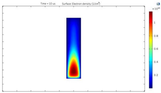 Figure 7: The electrons density time-dependence for hydrogen $(\mathsf{H}_2)$
Given the diagram, and distribution, looks exactly what we expected. Maximum value hydrogen electron density is of the order of magnitude $\sim 10^{16} - 10^{17}$; we can consider it close enough [6] to take the model as a valid representation. As the velocity of plasma steam propagation and the pressure i.e., pressure distribution, depend on the number of particles, i.e., electrons as the most mobile, their mobility, and distribution, a proper electron density diagram guarantees a valid consideration of velocity and pressure.
 (a)
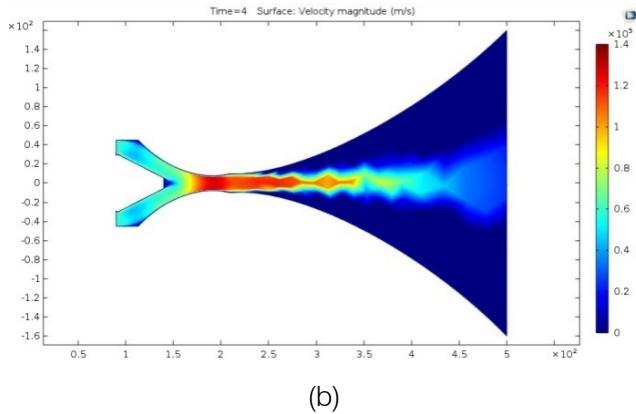
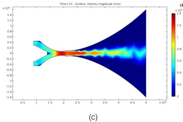
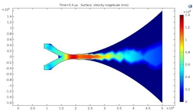
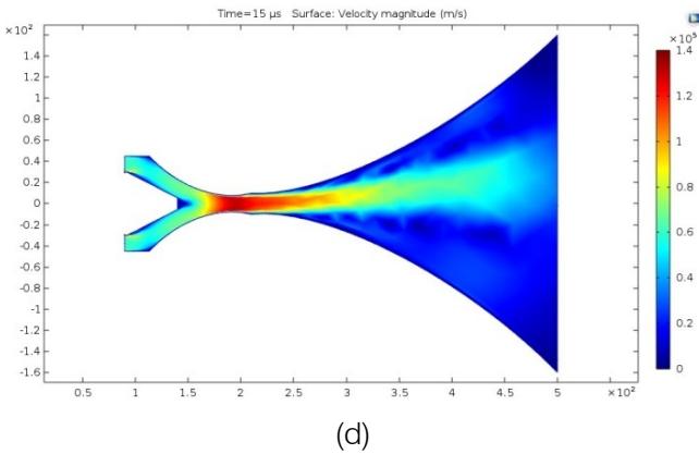 Figure 8: (a) (b) (c) (d) Velocity field in function of the displacement, during different time intervals
The study was carried out in such a way that the magnetic field defines the shape of the trajectory and the way of transporting particles through space. The propagation of the particles that form the plasma steam is limited by the magnetic field so that none of the particles can leave the cone that creates the magnetic field around them. On the other hand, the mobility of those particles, as well as their distribution, are expressed using diagram Figure 8. and Figure 9. Based on the velocity distribution diagram during time intervals, we can observe different forms of particle behavior, follow the velocity field, as well as various phenomena that occur.
The results are presented in different time intervals. The calculation itself is designed to give results for a $15\mu s$ performed in steps of $0.5\mu s$. In this work, only diagrams depicting some exciting or unusual phenomenon will be shown, and described. An essential approximation of the plasma thruster analysis in our case is the assumption that no particles will leave the cone that creates the magnetic field; in the real possibility there is probably particle dissipation outside the magnetic field itself. In the actual point the particles will probably move outside the cone of the magnetic field, but this should not have significant effects on the calculation results we are currently observing.
Analyzing the diagrams for the velocity of plasma propagation in Figure 8, we notice that the velocity increase with increasing compression, which is a consequence of the influence of the magnetic field. Since before the nozzle is congested, there is a gradual formation of closures, the nature of which lies in the pressure distribution. Based on Figure 9, it is seen that the congestion of the nozzle occurs due to the pressure drop in the tear of the nozzle. This tells us that when the magnetic field increase, there is a gradual increase in velocity, and a gradual decrease in pressure, until the moment of saturation.
Based on the diagram of Figure 8. (d), we can notice an exciting phenomenon that is also characteristic of the congestion of a convergent nozzle in fluid dynamics. The appearance of fluid steam, which leaks during converging nozzle throttling, doesn't continue moving along the abscissa, but the steam gradually moves upward. The reason for this occurrence is probably a decrease in pressure inside the plasma steam; it is obviously Figure 9. (d).
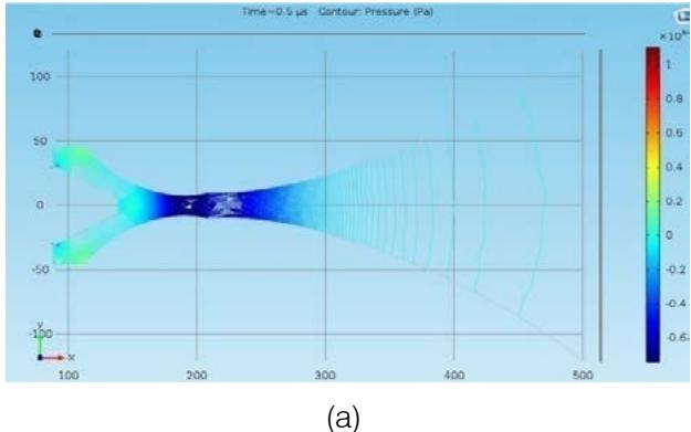
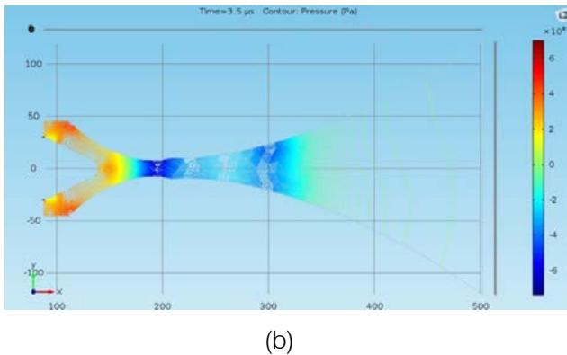
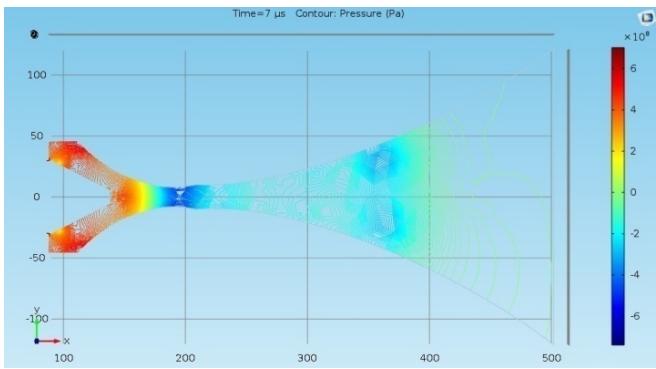
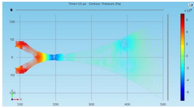 (c) (d) Figure 9: (a) (b) (c) (d) Distribution of Pressure in function of the distance, during time interval Figure 9. (d) shows a decrease in pressure around the plasma impulse, and according to the distribution of pressure inside the cone, we can determine that pressure around the plasma impulse is lower than the pressure in the environment, so plasma flow starts to rise upward.
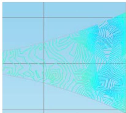 Figure 10: Pressure contour in turbulent regime obtained von Karman vortex streets
Also, it is vital to notice the presence of von Karman vortex streets in distributions of velocity (Figure 8. (b) (c)) and pressure (Figure 9. (b) (c) (d) and Figure 10) till the moment of congesting Figure 8. (d). This is an expected phenomenon for this flow type in fluid dynamics, which again proves the connection between fluid dynamics and plasma dynamics. After exiting at Mach number, less than or close to one, during exit from the nozzle, a transition will occur, and then turbulence, which appropriate values of the Reynolds number will generate von Karman vortex street.
## VI. DISCUSSION
For the case of gas leakage, when the Mach number is equal to one, or has small oscillations around one, based on the relation between the flow coefficient and Reynolds number, we can consider the mass flow as constant. Following, the total pressure is a sum of the pressure and the magnetic pressure $p + \frac{1}{2\mu_0} B^2$, the function of Mach number $\frac{M}{\left(1 + \frac{\aleph - 1}{2}M^2\right)^{\frac{\aleph + 1}{2(\aleph - 1)}}}$, and Reynolds number, mobility of charged particles are included in the equation by velocity.
$$
\dot{m} = \aleph \cdot v \cdot \left(p + \frac{1}{2\mu_0} B^2\right) \cdot \frac{M}{\left(1 + \frac{\aleph - 1}{2} M^2\right)^{\frac{\aleph + 1}{2(\aleph - 1)}}} \cdot A_{iz} = const
$$
The member $A_{iz}$ represent cross-surface at the point where the point where the plasma steam is narrowest. Based on the experiment, at the point of maximum constriction of the plasma steam, the diameter is between 1 cm and 1.2 cm, based on this, we can quickly determine the cross-section surface at the point of maximum constriction.
As already mentioned, the thrust, and the mechanical impulse of the plasma, will be calculated in the same way as a rocket engine; in the previous part of the text reason is explained. If using the previous formula for mass flow $\dot{m}$, use for combustion mass flow $\dot{m}_{c}$, the formula for plasma thrust:
$$
\vec{F}_{P} = \dot{m}_{c} \vec{v}_{i} = \aleph \cdot \left(p + \frac{1}{2\mu_{0}} B^{2}\right) \cdot \frac{M}{\left(1 + \frac{\aleph - 1}{2} M^{2}\right)^{\frac{\aleph + 1}{2(\aleph - 1)}}} \cdot A_{iz} \cdot v^{2} \cdot \vec{e}_{x}
$$
For the limiting value of the congestion of the convergent nozzle, when the mass flow is constant, the Mach number is approximately one $M = 1$, thus
$$
F_{P} = \left(p + \frac{1}{2\mu_{0}} B^{2}\right) \cdot \frac{\aleph \cdot A_{iz} \cdot v^{2}}{\left(1 + \frac{\aleph - 1}{2}\right)^{\frac{\aleph + 1}{2(\aleph - 1)}}}
$$
According to experimental results:
$$
F _ {P} = 1. 6 2 8 6 6 \cdot 1 0 ^ {5} N \sim 1 6 3 k N
$$
- specific thrust:
$$
F _ {S T} = 1. 3 6 \cdot 1 0 ^ {5} \frac {N s}{k g}
$$
- and mechanical impulse:
$$
I _ {p} = \int_ {0} ^ {1 0 ^ {- 5}} v \dot {m} d t = 2. 4 4 3 k g \frac {m}{s} \sim 2. 4 5 N s
$$
Based on [6], we notice that temperature and magnetic field are mutually dependent, leading us to the dependence of plasma velocity and temperature (Figure 11). For the reason that the magnetic field forms a convergent nozzle, while on the other hand, it depends of the temperature, we conclude that the Mach number for the plasma, directly depends on the temperature.
Since from fluid mechanics [1], we know that the Mach number depends on the ratio of the limiting velocity of the flow (sound speed) and the function of the square root of the temperature, which has the property of defining the current velocity of the flow. Compression for plasma flow can be expressed with $B^{2} = 4\mu_{0}nkT$ [6] and find that the magnetic field depends on temperature as a function of the square root, $B \propto \sqrt{T}$. As plasma velocity is directly proportional to magnetic field [3] $v \propto B$, we can conclude that velocity is proportional to square root of temperature $v \propto \sqrt{T}$, same as fluid mechanics, for $M = 1$, $v = \sqrt{kRT}$.
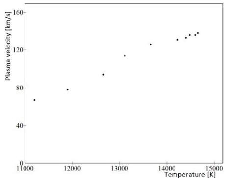 Figure 11: Plasma velocity in the function of temperature
According to experimental results in Figure 3, we notice that plasma velocity increase with the reduction of distance between the anode and cathode; we can easily conclude that the intensity of the magnetic field depends on distance between the anode and the cathode. This leads us to the fact that if we reduce the distance between the anode and the cathode, we increase the vector of the magnetic field. As the increase of the magnetic field vector leads to nozzle compression, the idea that the magnetic field can manipulate with a plasma nozzle, forming a convergent or convergence-divergence plasma nozzle, is founded. With an increase in the magnetic field vector, there is also an increase in the velocity of plasma discharge; according to the formula, the magnetic field vector is directly proportional to the velocity.
Of course, in specific moment, compression must reach a critical point, i.e., saturation of the flow rate, which will be analogous to the congestion of a convergent nozzle. According to that, we prove the initial hypothesis, and find another a critical correlation for the MHD model.
Also, I would like to point out another important observation, based on numerical results in Figure 9, as plasma velocity increase, fluid pressure decrease. However, as the pressure has its mechanical and magnetic components, and based on the previous formulas, as well as Alfven's speed [5], the magnetic pressure increases with the increase in the plasma velocity. Based on that behavior, we can conclude that the total pressure, the sum of mechanical and magnetic pressure, is a conserved quantity, i.e., if mechanical pressure increases, magnetic pressure must decrease, and vice versa.
It is necessary to emphasize that the numerical results are given only for the case when the Mach number for the plasma is equal or close to one. The formula for the velocity field, which is the basis of the numerical calculation, is derived so that the Mach number for the plasma is equal to one. This fact in no way diminishes the importance of research, on the contrary, this research helps to understand the properties of plasma better and gives us an excellent basis for further study. Because, if we have a limit value of plasma velocity, dependence of pressure, temperature, magnetic field, etc. - we can properly perform calculations for plasma nozzles.
If we continued to reduce the distance between the anode and the cathode, we would cause drop of the plasma velocity at a certain moment. With the reduction of the distance between the anode and the cathode, there would be an increase in energy of plasma, to such an extent that the cathode would begin to erode. The erosion of the cathode would be manifested as a drop in plasma velocity. Anode erosion would be minimal or doesn't exist at all, due to the geometry of the anode.
I would like to point out that we are nearing the end of making a cathode with compact geometry, which should completely neutralize the erosion of the system, or minimize it as much as possible. One of the key problems is the conditions for the testing of such an assembly, because it can cause catastrophic consequences such as the explosion of the equipment, or even the release of neutrons, which would lead to catastrophic consequences for the environment. In our laboratory, we don't have the conditions for such an experiment. However, a positive result would have a multiple benefits. I am convinced that it is possible to create a sufficiently strong rotating magnetic field, which would be able to capture the plasma beam, and under the influence of such a strong magnetic field, could become a secondary particle accelerator perpendicular to the original direction. This accelerator would actually be the basis for a plasma reactor. Invention of plasma reactor is surely a capital discovery.
## VII. CONCLUSION
According to the presented results, and compared with similar research, we can find the following conclusion. Based on the experimental results, all assumptions from the beginning proved to be accurate so that the experiment can be considered as positive.
A significant invention is undoubtedly the ability of a magneto-plasma compressor (MPC) to produce buoyant force, and trust, which leads us directly to the idea of a plasma thruster. But, this ability is not enough for itself; the essential thing is an equation that can describe this occasion, and closely explain the phenomenon. Based on experimental results, we proved the initial assumption that the plasma velocity, during the boost of the convergent nozzle, must reach a specific limit value. According to this value, we find the existence and approximate value of the Mach number for plasma. Helped by the presence of a limit value for plasma velocity in a convergent nozzle, we allowed every feature observation of plasma easier; using a value of one for Mach number, we can consider mass flow constant.
Also, we find that magnetic fields manipulate with plasma steam movement, field of velocity, pressure distribution, etc. - basically, we use magnetic fields to determine flow features. With the help of the magnetic field, we can define the shape of the nozzle, therefore the condition of the plasma flow, the concentration of particles per unit volume, and in this way the intensity of the electric current, the temperature, such as the velocity of the flow. Finding the values mentioned physics quantities, as well as a closer explanation of the specific phenomena that participate in plasma propulsion at $M \cong 1$, is the first step towards the realization of plasma thruster.
We can also conclude that the mechanical, thermodynamic, and electrical properties of the plasma thruster don't depend on the working gas. The exact relation will apply to different working gases, i.e., magnetic field, pressure, and temperature; they will have the same roles and dependencies, only the constant will be other. In addition to the gas constants that necessarily change with the change of the working gas, it is essential to note that the limiting value of the plasma velocity will be different, i.e., lower than the plasma velocity when the working gas is hydrogen.
Although the experiment was supposed to give us an approximate model for observing the plasma thruster, I think we got more than expected. Of course, this is only the first step toward the realization of a plasma thruster, but it is a significant step. We received outlines, ideas, how the plasma thruster should look, as well as guidelines for future experiments, which can be carried out based on this work.
In addition to the obtained results, the long-term relevance of this work can be seen in the opening of an ample space for new research and new ideas.
### ACKNOWLEDGEMENT
I owe a lot of thanks to dr Milorad Kuraica, dr Predrag Iskrenovic and dr Nikola Davidovic.
Work is dedicated to prof. Vasko Fotev and prof. Nikola Sisovic.
Milica Marković,Miroslav Kuzmanović,Igor Pašti,Danica Bajuk-Bogdanović,Dragan Ranković,Dušan Dimić (1989). EFFECTS OF HYDROCHLORIC, HYDROFLUORIC, AND ACETIC ACID ON PIG BONE ESTIMATED BY FTIR, RAMAN, LIBS, AND SEM-EDX.
P Yuri (1987). Fig. 7. Academician of the USSR Academy of Medical Sciences, Professor Yuri Aleksandrovich Pankov (1930–2016). Director of the Institute of Experimental Endocrinology and Hormone Chemistry (IEECHG) of the USSR Academy of Medical Sciences from 1983 to 1988 [18].
A Morozov (1990). Development of the principles of a quasi-steady-state plasma accelerator with an intrinsic magnetic field with a power of 10 <sup>9</sup> –10 <sup>11</sup> W.
H Alfven (1942). Existence of Electromagnetic-Hydrodynamic Waves.
J Puric,I Dojcinovic,V Astasinjski,M Kuraica,B Obradovic (2004). Electirc and Tehrmodyniamic Properties of Plasma Flows Created by a Magnetoplasma Compressor.
Donald Pellinen,Marco Di Capua,Stephen Sampayan,Harold Gerbracht,Ming Wang (1980). Rogowski coil for measuring fast, high-level pulsed currents.
N Nachev,M Fedorov (1977). Teorija aviacionih gazoturbinnih dvigatelei.
V Abianc (1953). Teorija aviacionih gazovih turbin.
A Morozov (1975). The conceptual development of stationary plasma thrusters.
Luka Božić,Antonije Jeremić,Todor Aleksandrović,Aleksandar Milić (2020). COMPARATIVE ANALYSIS OF SINGLE-PHASE AND INTERLEAVED SYNCHRONOUS BUCK CONVERTERS.
Lj,Ristovski (1986). Unknown Title.
A Morozov (1974). Fizika i primenie plazmenjih uskoritelij.
J Lowke (1997). A Unified Theory of Arcs and their Electrodes.
G Hauke,T Hughes (1994). A unified approach to compressible and incompressible flows.
Duane Deardorff,Andrew Graham (2003). The National Institute of Standards and Technology Reference on Constants, Units, and Uncertainty, http://www.physics.nist.gov/cuu/Uncertainty/index.html.
(null). A Guide to Simulation of Electroanalytical Experiments at Microelectrodes using COMSOL Multiphysics.
No ethics committee approval was required for this article type.
Data Availability
Not applicable for this article.
How to Cite This Article
Milovan Pavlovic. 2026. \u201cExperimental and Numerical Determination of Limit Velocity for Plasma Thruster\u201d. Global Journal of Science Frontier Research - A: Physics & Space Science GJSFR-A Volume 23 (GJSFR Volume 23 Issue A6).
Explore published articles in an immersive Augmented Reality environment. Our platform converts research papers into interactive 3D books, allowing readers to view and interact with content using AR and VR compatible devices.
Your published article is automatically converted into a realistic 3D book. Flip through pages and read research papers in a more engaging and interactive format.
Our website is actively being updated, and changes may occur frequently. Please clear your browser cache if needed. For feedback or error reporting, please email [email protected]
Thank you for connecting with us. We will respond to you shortly.