I. INTRODUCTION
In industrial buildings, square hollow steel columns are regularly utilized, but they are employed more regularly in supporting structures for bridge design. These columns are produced in stiffened and unstiffened box hollow columns having compact, noncompact and slender cross sections. The global and local buckling are two different buckling modes that can occur in compression steel elements. The primary effect of local and global buckling is a reduction of the stiffening and loading capacity of the member. The local and global buckling mode is significant affected by the ratio ratio, ratio, and boundary conditions of the member. The initial imperfections, residual stress, and boundary conditions are critical factors in determining the ultimate strength of square hollow steel columns in compression members[1].
Many investigations on the behavior of square hollow steel columns have been conducted in the recent decades. The stiffened and unstiffened square hollow columns (SHC), rectangular hollow columns (RHC) were investigated by Tao et al. [2]. The stiffened square hollow columns has only two longitudinal stiffeners welded to its longer sides as opposed to the four longitudinal stiffeners that were once present on each side of the stiffened square hollow columns (SHC). One of the most important considerations was the ratio . The tubes also come with or without stiffeners. Comparing the ultimate strength of the experimental test results are presented.
A comparison experiment test study between unstiffened and stiffened stainless steel hollow columns was presented by Dabaon et al. [3]. The ratio of length-to-depth was fixed at a value of 3, but the depth-to-thickness ratio fluctuated from 60 to 90. For stiffened and unstiffened sections, the ultimate strengths of this columns, buckling modes, and axial load verses axial strain are compared.
Somodi and Kövesdi [4] focuses on the experimental measurements of the residual stress on welded box steel hollow columns with different steel grades and different B/t ratios. The aim of this investigation is to estimate the residual stresses, to determine the maximum compressive and tensile residual stresses.
The experimental tests and finite element (FE) method of hollow long steel columns with non-compact and compact unstiffened sections were developed by Khan et al. [5]. The experimental test results concluded that the non-compact sections with collapsed as a consequence of the combination of global and local buckling (G and L). Moreover, the compact cross-sections having values between 35 to 109 collapsed in accordance with global buckling. According to the test data of estimation of slender noncompact box sections, it is necessary take into account that the reduction factor resulting from the global and local buckling effects.
Javidan et al.[6] studied the behavior and ultimate strength of an innovative steel hollow long column. The suggested innovative columns are made of mild steel plates that are joined at the corners to mild steel tubes. According the test and FE modeling, a special focus is given to the effect of fabrication initial imperfections, and residual stresses, and welding methods on the behavior of the suggested long hollow columns. Because of the compatibility between the steel plates and tubes in the column, the studied innovative steel hollow column specimens are demonstrated to have excellent compressive behavior, which significantly increases their strength and ductility.
El-Sayed et al. [7] presented a novel polymer-mortar system that strengthened square hollow columns, proving their behavior and strength. According to the square hollow short columns strengthened using polymer-mortar layer with the thickness equal to , a maximum axial strength improvement of was achieved. For long columns, a polymer-mortar layer applied in thickness on all four sides resulted in a ultimate strength gain of .
Zheng et al. [8] studied the impacts of cold-forming in the behavior of stainless steel cold-formed hollow steel tube columns. In this investigation a total of 19 and 32 specimens were tested for short and long columns, respectively. The buckling modes of the experimental specimens included the global buckling, local buckling, local-global buckling, and material strain hardening after yielding. The experimental test specimens collapsed in four different modes: global, local, both local-global, and plastic strength after yielding.
Cold-formed hollow columns made of lean duplex stainless steel (LDSS) were designed and demonstrated by Anbarasu and Ashraf [9]. These columns that mainly collapsed due to the interaction of flexural and local buckling modes. In this study, the geometric parameters of the (LDSS) hollow column sections were selected so that the local and global buckling stresses are almost equal.
Nassirnia et al. [10] developed a novel hollow columns made of ultra-high-strength steel tubes and corrugated plates. The corrugated plates that make up the suggested novel produced columns are welded to ultra-high strength (UHS) steel tubes and have a yield stress of at the edges. The yield stress of the steel tube The results demonstrated that the suggested novel columns are very efficient and ductile under axial compression loads.
The finite element (FE) investigation of the fixed ended LDSS slender hollow columns with square (SHC), and non-regular hollow columns (NRHCs) was developed by Patton and Singh [11]. The non-regular hollow columns (NRHCs) such as L-(LHC) and T-(THC) shaped cross-sections. The Abaqus software was used to create the finite element (FE) models was conducted to under pure axial compression. The the finite element (FE) results of square hollow columns and non-regular hollow columns were then compared with the design equations by the ASCE 8-02 and EN1993-1-4 requirements. The finite element results and code predictions have been demonstrated to agree significantly.
Schillo and Feldmann [12] investigated the both global and local buckling mods of the steel square hollow columns. The experiments were verified with the FE using Ansys software. The research presents an analytical method for determining a reduction factor that depends on slenderness. The finite element modeling of experimental tests on slender square hollow columns, subject to combined global and local buckling of steel plates was developed by Pavlovcic et al. [13]. The parametric investigation used in the FE analysis are the influence of different imperfections, the cross-section geometry for cold-formed and welded columns, and the columns length. According to the results of a study, the initial imperfection can reduce resistance by up to compared with perfect column.
The nonlinear finite element (FE) analysis of the square hollow stiffened and unstiffened high strength stainless steel (HSS) columns was developed by Ellobody[14]. The column ultimate strengths, the axial load-shortening curves, and the collapsed modes were predicted for the unstiffened and stiffened columns. The main objective of this study was to investigate the effects of various section geometries on the columns strength. Hilo et al. [15] studied the FE analysis on the ultimate strength and behavior of polygonal hollow steel tube columns under axial compression load. In this investigation, different cross sections, including rectangular, circular, square, pentagonal, and hexagonal ones, have been provided. The finite element models have been analyzed to find the effect of the different cross-section shape, thickness, and length on the axial load behavior of the polygonal hollow steel tube columns.
The FE analysis on the ultimate strength and behavior of cold-formed steel rectangular and square hollow columns with two opposing circular holes in the center, at the height of the column was studied by Singh et al. [16]. The parametric analysis has been carried out, taking into account a wide range of cross-sectional slenderness and the size of the circular holes.
The mechanical performance of the hollow steel columns is significantly impacted by sectional residual stress. The sectional residual stress have been conducted by Ban et al. [17], Cao et al. [18], and other researchers. These investigations were carried out to study the effect of the residual stress on the behavior and ultimate strength of hollow steel columns. They concluded that the sectional residual stress has a significant effect on the buckling capacity and behavior of hollow columns under axial compression loads.
In case of the stiffened hollow steel columns, it is observed that there has been just a limited amount of study conducted under monotonic loading including the local and global buckling effects. The present study aims to investigate the performance and ultimate strength of stiffened square hollow columns in the short as well as long columns, under axial compression loads.
Based on the non-linear finite element (FE) analysis, this investigation was carried out to evaluate the influence of major steel tube columns parameters such as stiffener length, the ratio , and yield strength on the hollow steel short column's performance. The main objective of the parametric study was to develop a novel mathematical equation to predict the ultimate strength of box steel sections, in addition the study was conducted on effect of the stiffeners length and propose a novel equation to calculate the optimal stiffeners length. The comparison between the current (FE) results and analytical methods is presented. In case of the long columns, a comparison was made for the stiffened and unstiffened sections to investigate how the stiffeners affect the columns ultimate strength. The numerical study is briefly described, with the variable parameters being and the ratio equals to (50-12.5).
II. FINITE ELEMENT MODELING
a) General Description
In this investigation, the finite element software ABAQUS [31] is used to create an accurate finite element model for estimating the behavior and ultimate strength of the steel tube columns with regard to axial compression loads.
b) Initial Imperfection
The initial imperfection of the hollow square columns was taken into account in the load-deflection
If mm:
analysis. It is assumed that the first buckling mode shape obtained from the eigen value buckling analysis is the shape of the local and global initial imperfections. The Japan Standard for Highway Bridges (JSHB) [19] prescribes maximum initial global displacement as . The AISC 360-05 [20] prescribes maximum initial displacement as . According to experimental measurements in [13], the global imperfection in the Y- and X-direction for hollow long columns appeared to be around . For square hollow columns in this study, the initial imperfection value was taken as for local buckling and for global buckling according to Chinese Standard GB50018-2002 [21].
c) Residual Stresses
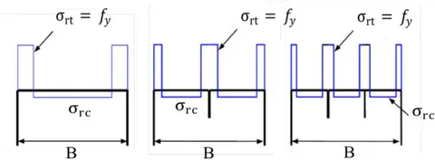
In this paper, according to the experimental test result by Somodi and Kovesdi [4], To estimate the compressive residual stresses, two models of the residual stress are developed. Equations (1) and (2) were developed to provide the best approximation to the average compressive residual stresses that were measured. The "predefined field" for the initial stress option is available in FE software to model residual stress. The typical residual stress distribution of the steel square hollow stiffened and unstiffened sections are shown in Figure 1.
If mm:
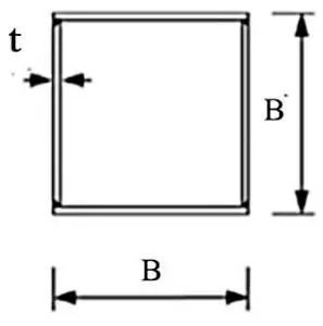
Where (mm) and (mm) is the thickness and width of the steel box columns, respectively.
d) Material Model
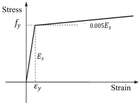
In this research, the hollow square columns was modeled by the elastic-plastic model, as shown in Figure 2. The Poisson's ratio was considered to be 0.3. In addition, the plastic zone is with a linear hardening and the hardening modulus was considered
with is the elastic modulus of steel [22]. The ultimate strength is clearly not significantly affected by The use of steel relationship, and the load-deformation curve is only slightly affected. Only slightly affects the load-deformation curve at a later stage [23].
III. FINITE ELEMENT MODELING VALIDATION
The FE model's accuracy in the present parametric study was verified using previous experimental test results. The verification study, was carried out on, two short square columns that were tested by Tao et al. [2] and four long columns that were tested by Khan et al. [5].
a) Material and Geometric Properties
For short columns, the steel material for the finite element models was assumed to be the elastic-plastic model as shown in Figure 2. The yield strength , Elastic modulus , yield strain (%) 0.137, and the ultimate strength . The investigated specimens' labels and geometric properties are shown in Table 1 and Figure 3.
| No. | Specimen label | B(mm) | L(mm) | D/t | hs×ts |
| 1 | SS25 | 250 | 750 | 100 | 35×2.5 |
| 2 | US25 | 250 | 750 | 100 | --- |
![Figure 3: The specimens investigated by Tao et al. [2]](https://doc.globaljournals.org/shao23_55668/ocr/images/derivatives/90/90ab3a7fe18e4f2c0614e43015ec70a69357a7e07d0b27d6306c13c254b74d63.webp)
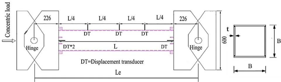
For long columns, the steel material for the finite element models was assumed to be an elastic-plastic model as shown in Figure 2. The yield strength , The elastic modulus , The yield strain 0.4157 (%), and the ultimate strength . The verification was performed for slender welded box sections with and 59) and and 0.8). The dimensions of test specimens are shown in Table 2 and the illustration of the experimental test layout is shown in Figure 4.
| Test specimens | B (mm) | t (mm) | B/t | Le (mm) | Le/r | be/b |
| HS15SL2 | 74.57 | 4.93 | 15 | 2512 | 77 | 1.0 |
| HS25SL3 | 125.20 | 4.92 | 25 | 3512 | 66 | 0.8 |
| HS25SL1 | 125.21 | 4.92 | 25 | 1512 | 28 | 0.8 |
| HS20SL2 | 99.39 | 4.92 | 20 | 2512 | 59 | 1.0 |
b) Loading and Boundary Conditions
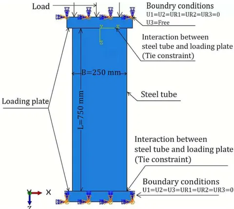
In fact, there are two types of loading application methods: force-controlled loading and displacement-controlled loading. In this paper, force-controlled loading technique was used. The square hollow columns were modeled using the Finite Element Analysis (FEA) under monotonic loading. In case of short columns, two loading plates coupled with a steel tube by tie constraints were used. The boundary condition of the finite element (FE) model was set at the loading plate, as shown in Figure 5. The axial load was applied by carrying out a distributed load on the loading plate.
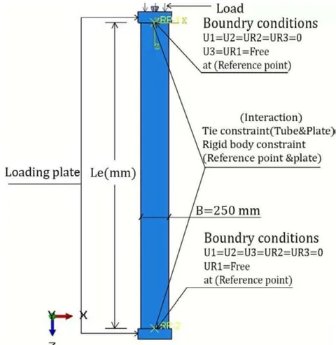
In the case of long columns, two reference points have been created and constrained to the loading plate of all hollow square columns specimens by rigid body constraints and set the boundary condition of the (FE) model at the reference point. Both column ends were modeled as pinned condition, i.e., both ends were free to rotate. While the upper end was unconstrained in the vertical axis to apply the external load. The square steel tube coupled with the loading plate by tie constraint is shown in Figure 6. The axial load was applied in the form of distributed load on the loading plate.
c) Element Type and Mesh
The short hollow columns in this study were modeled using 4-node reduced integration doubly curved thin or thick shell element (S4R). The loading plate was modeled using 4-node linear tetrahedron element. The approximate global element size was used in this study. While in case of hollow steel long columns, the (C3D4) 4-node linear tetrahedron element was used. In addition, the approximate global size equal to was used in this study.
d) Accuracy of Adopted Models
i. Short Columns
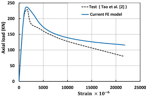
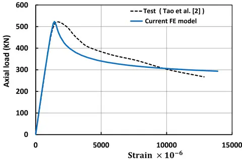
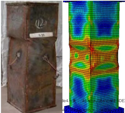
The comparison of the experimental test results and the finite element results for the US25 and SS25 specimens are shown in Figure 7 and Figure 8, respectively. The mean values of the ratio between axial load deduced by FE and test are 1.02, and 1.01 for the US25 and SS25 specimens, respectively. From this study, the predictions of ultimate strengths are very close to the test given by Tao et al. [2]. In addition, the mode of failure due to buckling obtained from the geometric nonlinear buckling FE analysis is shown in Figure 9.
ii. Long Columns
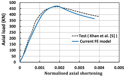
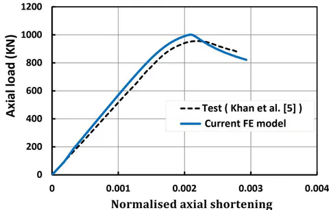
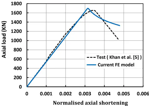
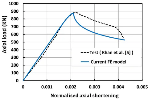
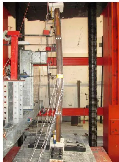
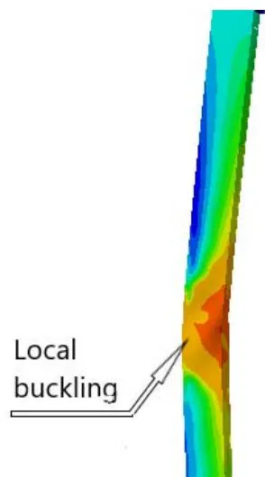
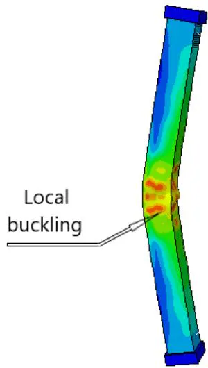
The comparison of the experimental test results and the finite element (FE) results for the HS15SL2, HS25SL3, HS25SL1, and HS20SL2 specimens are shown in Figure 10, Figure 11, Figure 12, and Figure 13, respectively. The mean values of are, respectively, 1.01, 1.03, 1.02, and 0.99 for the HS15SL2, HS25SL3, HS25SL1, and HS20SL2 specimens. From this study, the predicted ultimate strengths are very close to the given by tests in Khan et al. [5]. The HS15SL2 and HS20SL2 specimens with unstiffened compact section with and and 59, respectively, failed due to global buckling only. The comparison of the buckling modes for the experimental test and FE model is shown in Figure 14 for the HS15SL2 specimen. The HS25SL3 and HS25SL1 specimens, with unstiffened slender sections with and and 28, respectively, failed due to interaction between global and local buckling. The failure buckling modes for the HS25SL3 and HS25SL1 specimens are shown in Figure 15.

IV. PARAMETRIC STUDY
a) General Description
Based on the study of verification, A parametric investigation was carried out to create three-dimensional finite element models that simulate the stiffened and unstiffened hollow steel columns under axial compression. These models focus on the global and local buckling and were divided into two cases. Case 1 studies the local buckling's effects on the behavior and ultimate strength of hollow steel short columns. Case 2 studies the influence of stiffeners on the ultimate strength and performance of hollow steel long columns. The non-linear finite element (FE) analysis is used in the study to understand the effect of main structural parameters such as , stiffener length, the ratio of width-to-thickness , and the yield stress on the hollow steel column performance.
b) Columns Geometry
i. Short Columns
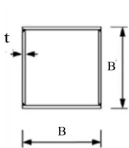
The steel material model for the finite elements was assumed to be an elastic-plastic model as shown in Figure 2, in addition taken as the hardening modulus equal to . The Young's modulus and Poisson's ratio . The studied parameters were the yield strength , and , the stiffeners length , and the ratio . The columns length is and the columns width is for all the specimens. The thickness of the stiffeners is considered same as the thickness of the tube, as listed in Tables (3 and 4). The shapes and dimensions of the investigated steel columns are shown in Figure 16. The specimen label shows the whether the sections is unstiffened (US), stiffened using single stiffener per section wall (SS), or stiffened using double stiffener per section wall (DS). In addition, the label suffixed by the thickness of the section walls in (mm).
The boundary condition as described previously and shown in Figure 5. For square hollow columns in these investigation, the initial local imperfection's value has been set to . In addition, this study used the distribution of residual stress shown in Figure 1. The columns in this study were modeled using 4-node shell elements (S4R) and the approximate global size of the mesh is about .
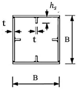
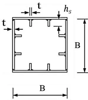
Unstiffened sections (US) Stiffened sections with one stiffener (SS) Stiffened sections with two stiffeners (DS) t mm fy MPa B t t mm fy MPa (B/t) t mm fy MPa (B/t) 1 240 250 1 240 250 1 240 250 1.5 240 167 2 240 125 2.5 240 100 2 240 125 2.8 240 89 4 240 63 3.2 240 78 4.5 240 55 6 240 42 5.1 240 48 6.7 240 37 8 240 31 7.7 240 32 9 240 28 1 360 250 10 240 25 1 360 250 2.5 360 100 16 240 16 2 360 125 4 360 63 1 360 250 2.8 360 89 6 360 42 1.5 360 167 4.5 360 55 8 360 31 2 360 125 6.7 360 37 1 460 250 3.2 360 78 9 360 28 2.5 460 100 5.1 360 48 1 460 250 4 460 63 7.7 360 32 2 460 125 6 460 42 10 360 25 2.8 460 89 8 460 31 16 360 16 4.5 460 55 1 560 250 1 460 250 6.7 460 37 2.5 560 100 1.5 460 167 9 460 28 4 560 63 2 460 125 1 560 250 6 560 42 3.2 460 78 2 560 125 8 560 31 5.1 460 48 2.8 560 89 1 779 250 7.7 460 32 4.5 560 55 2.5 779 100 10 460 25 6.7 560 37 4 779 63 16 460 16 9 560 28 6 779 42 1 560 250 1 779 250 8 779 31 1.5 560 167 2 779 125 - - - 2 560 125 2.8 779 89 - - - 3.2 560 78 4.5 779 55 - - - 5.1 560 48 6.7 779 37 - - - 7.7 560 32 9 779 28 - - - 10 560 25 11.3 779 22.1 - - - 16 560 16 12 779 20.8 - - - Unstiffened sections (US) 1 779 250 7.7 779 32 1 779 250 1.5 779 167 10 779 25 1.5 779 167 2 779 125 16 779 16 2 779 125 3.2 779 78 18 779 13.8 3.2 779 78 5.1 779 48 20 779 12.5 5.1 779 48 Stiffened sections with one stiffener (SS) Stiffened sections with one stiffener (SS) Stiffened sections with two stiffeners (DS) Stiffened sections with two stiffeners (DS) t mm hs mm t mm hs mm t mm hs mm t mm hs mm 1 10 1 40 2 10 2 50 1.5 10 1.5 40 3.2 10 3.2 50 2 10 2 40 5.1 10 5.1 50 3.2 10 3.2 40 7.7 10 7.7 50 5.1 10 5.1 40 10 10 10 50 7.7 10 7.7 40 16 10 16 50 10 10 10 40 2 20 2 60 16 10 16 40 3.2 20 3.2 60 1 20 1 50 5.1 20 5.1 60 1.5 20 1.5 50 7.7 20 7.7 60 2 20 2 50 10 20 10 60 3.2 20 3.2 50 16 20 16 60 5.1 20 5.1 50 2 30 - - 7.7 20 7.7 50 3.2 30 - - 10 20 10 50 5.1 30 - - 16 20 16 50 7.7 30 - - 1 30 1 60 10 30 - - 1.5 30 1.5 60 16 30 - - 2 30 2 60 2 40 - - 3.2 30 3.2 60 3.2 40 - - 5.1 30 5.1 60 5.1 40 - - 7.7 30 7.7 60 7.7 40 - - 10 30 10 60 10 40 - - 16 30 16 60 16 40 - -
ii. Long Columns
The steel material for the finite element models was assumed to be an elastic-plastic with linear hardening model. In addition the hardening modulus has been set to equal to as shown in Figure 2. The Young's modulus and the Poisson's ratio . The boundary condition as described previously and shown in Figure 6. For square hollow columns in these investigation, the initial global imperfection value was taken as . The studied parameters were the columns length and the ratio , as listed in Tables (5 and 6). In addition, the columns width for all specimens, the yield strength is used in this study , and the stiffeners length . The thickness of the stiffener is the same as the thickness of the tube. The specimens investigated are shown in Figure 17. The specimens' labels are as follows:
- (US - t - L) = (US) Unstiffened section - (t) thickness - (L) column length.
- (SS - t - L) = (SS) Stiffened section with one stiffener-(t) thickness - (L) column length.
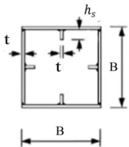
No. Specimen label (B/t) KLr 1 US-20-2750 12.5 29.2 2 US-20-3000 12.5 31.8 3 US-20-4000 12.5 42.4 4 US-20-5000 12.5 53 5 US-20-6000 12.5 63.7 6 US-20-7000 12.5 74.3 7 US-20-8000 12.5 84.9 8 US-5-3000 50 30 9 US-5-4000 50 40 10 US-5-5000 50 50 11 US-5-6000 50 60 12 US-5-7000 50 70 13 US-5-8000 50 80 14 US-5-9000 50 90
Table 6: The dimensions of the stiffened sections with one stiffener, where the ratio
and 50
| No. | Specimen label | (B/t) | |
| 1 | SS-20-3000 | 12.5 | 33.1 |
| 2 | SS-20-4000 | 12.5 | 44.1 |
| 3 | SS-20-5000 | 12.5 | 55.1 |
| 4 | SS-20-6000 | 12.5 | 66.2 |
| 5 | SS-20-7000 | 12.5 | 77.2 |
| 6 | SS-20-8000 | 12.5 | 88.2 |
| 7 | SS-20-9000 | 12.5 | 99.2 |
| 8 | SS-5-1000 | 50 | 10.3 |
| 9 | SS-5-2000 | 50 | 20.6 |
| 10 | SS-5-3000 | 50 | 30.9 |
| 11 | SS-5-4000 | 50 | 41.2 |
| 12 | SS-5-5000 | 50 | 51.5 |
| 13 | SS-5-6000 | 50 | 61.8 |
| 14 | SS-5-7000 | 50 | 72.1 |
| 15 | SS-5-8000 | 50 | 82.4 |
c) Results and Discussion of Parametric Study
i. Unstiffened Short Columns FE Results against Analytical Methods
Most standards and specifications use the effective width approach to take into account the local buckling in case of the slender hollow steel tube cross-sections. This theory was developed based on
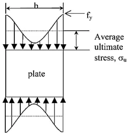
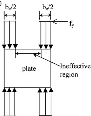
The values of in Table 7 give the reduction factors of the strength for the numerical models, where . Where, represents the ultimate loads, takes into account the reduction due to local buckling's effects according to the effective width approach by Uy[24]. The local buckling reduction factor is determined using Eq. (3) and (4), where the ratio is the effective tube width ratio to full tube width. When equals 1.0, this means that the sections being compact.
Where for heavily welded tubes. Which accounts for geometric imperfections and residual stress. The stress of local buckling is presents in Eq. (4), as shown below:
Where the coefficient of plate buckling can be considered as 4 for hollow sections and . Von Karman et al. [28] developed the first effective width expression in 1932. This expression states that a width of plate and effective width can be used to evaluate the ultimate strength capacity. Von Karman's effective width can be written in terms of the yield stress and critical stress as follows:
Where:-
Where the buckling coefficient in case of the simply supported plate. Winter [29] subsequently modified von Karman's equation to:
The second term within the bracket out Winter equation is mainly at the point where the applied edge stress and yield stress are similar. According to the Direct Strength Method (DSM) by ANSI/AISI S100-16 [25], the theoretical equation to estimating the ultimate loads with take into account the local buckling as given in Eq. (8). Where the is the critical elastic local buckling load of the square hollow columns and is the non-cross-section slenderness of the cross-section and equals to .
Where in (MPa) and in .
Fang and Chan [26] modified the direct strength method to give the predictions of safer strength for welded steel hollow columns, as shown in Eq. (9).
In this investigation, the main objective of the analytical methods is to study the local buckling's effects on the steel tube ultimate strength and compared with the current (FE) results. Eight FE models of unstiffened short columns was used in this case, where the ratio varying from 16 to 250. According to most of the international codes like ANSI/AISC 360-16 [30] the dimensions used in these investigation provide valuable data for slender, non-compact, and compact sections. The hollow steel sections, according to ANSI/AISC 360-16 are classified for local buckling.
If The tube is a compact section
The tube is a non-compact section
The tube is slender cross-sections
Where:
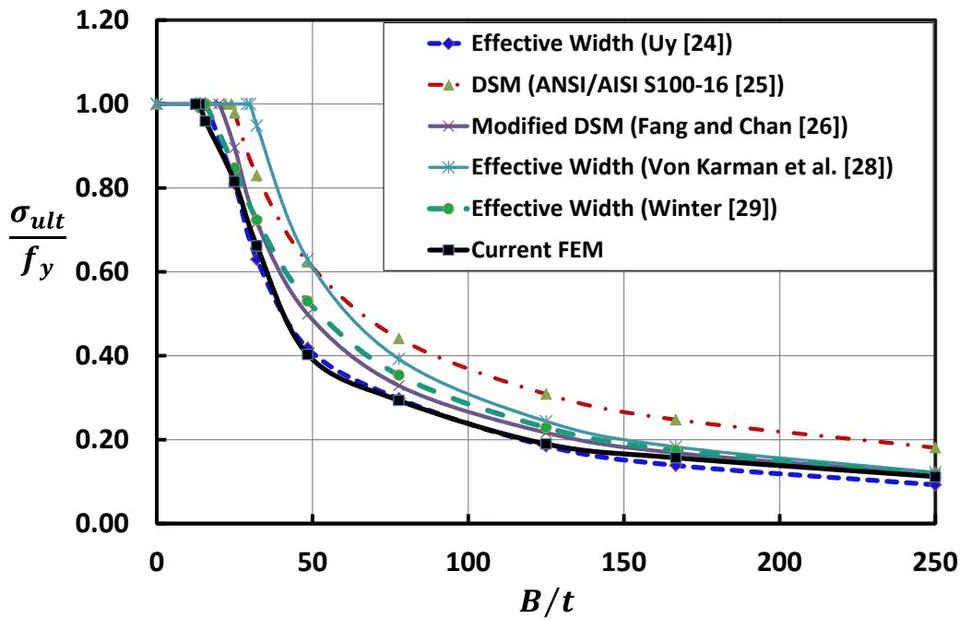
The comparison of the analytical and the FE results for the unstiffened steel columns is summarized in Figure 19 and Table 7. According to this comparison, the present FE results produces conservative predictions of the steel tube ultimate. In addition that the average variation is around between current FE models and the effective width approach by Uy[24]. As well as that, the average variation is around between current FE models and modified (DSM). From this comparison, the results of present (FE) and the effective width method by Uy[24] approximately similar. This is because the current FE models and the effective width method by Uy[24] take into accounts for geometric imperfections and residual stress. Thus, it can be concluded that the proposed method can accurately predict the ultimate load capacity of short columns.
| Specimen label | Bt | σUlt/fy | |||||
| Present FEM | Uy [24] | Modified DSM [26] | Winter [29] | DSM [25] | Von Karmans[28] | ||
| US-1 | 250 | 0.11 | 0.09 | 0.12 | 0.12 | 0.18 | 0.12 |
| US-1.5 | 167 | 0.16 | 0.14 | 0.17 | 0.17 | 0.25 | 0.18 |
| US-2 | 125 | 0.19 | 0.18 | 0.22 | 0.23 | 0.31 | 0.24 |
| US-3.2 | 78 | 0.29 | 0.30 | 0.33 | 0.35 | 0.44 | 0.39 |
| US-5.1 | 48 | 0.40 | 0.42 | 0.50 | 0.53 | 0.62 | 0.63 |
| US-7.7 | 32 | 0.66 | 0.63 | 0.72 | 0.72 | 0.83 | 0.95 |
| US-10 | 25 | 0.82 | 0.81 | 0.90 | 0.85 | 0.98 | 1.00 |
| US-16 | 16 | 0.96 | 1.00 | 1.00 | 1.00 | 1.00 | 1.00 |
ii. Stiffened Short Columns FE Results against Analytical Methods
This case deals with stiffeners in steel tube fields subjected to axial stress. There are two primary types of stiffeners:
- Longitudinal stiffeners, that are aligned with the steel tube length direction.
- Transverse stiffeners, that are aligned normal to the length direction of the steel tube.
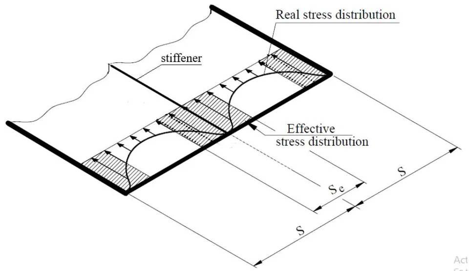
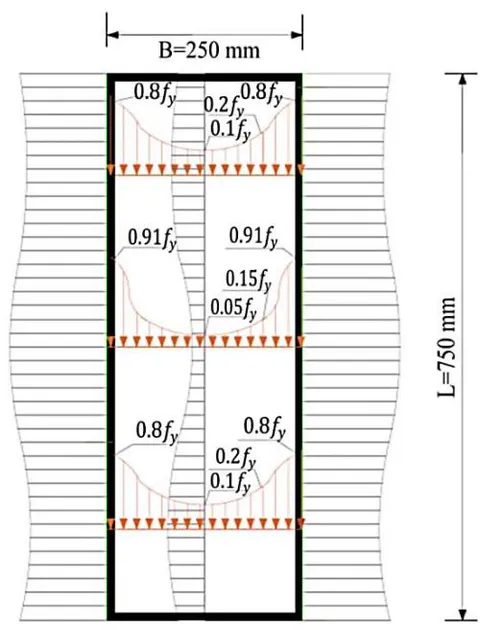
The stiffeners can be attached to the four walls of the tube, and it is used to control the local buckling this tubes. In this study, the steel tube is without transverse stiffeners, so it is possible that the stiffener could buckle locally or could be ineffective when the stiffener length is small. There are different formulas to account for stiffeners such as the effective plate width according to Norsok standard (N-004) [27]. This standard was developed depends on a steel tube's redistribution of stress as shown in Figure 20. The effective width for the stiffened sections subjected to longitudinal stress is found from:
The reduction factor in the longitudinal direction, , is found from:
Where:
is the reduction factor for compression stresses in the transverse direction.
is the reduction factor for shear.
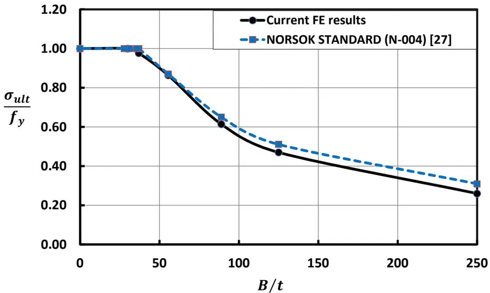
The comparison of the analytical results and the FE results is summarized in Figure 21 for the stiffened sections with one stiffener, where and . The Norsok standard does not consider the effect of the stiffeners' length in calculating the section capacity. In this case the stiffeners may be failed due to the local buckling. Therefore, the current FE results produce conservatively predictions of the steel tube ultimate strength for stiffened steel columns. In addition that the average variation is around between current FE models and the effective width method by Norsok. In this case, where , the predictions of ultimate strengths by current FE are very close to the effective width method by Norsok. This is due to the stiffeners most likely not exhibiting any local buckling. In addition, where the current FE results produce conservative predictions of the ultimate strength. This is due to the stiffeners most likely exhibiting local buckling.
iii. Comparison between Stiffened and Unstiffened Hollow Short Steel Columns
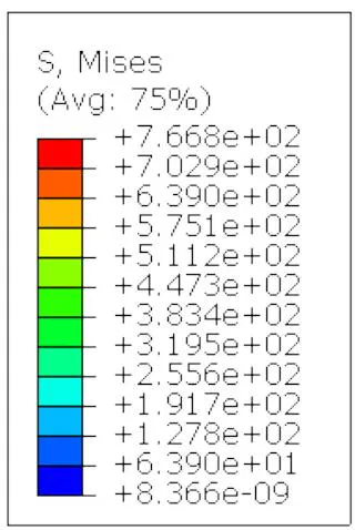
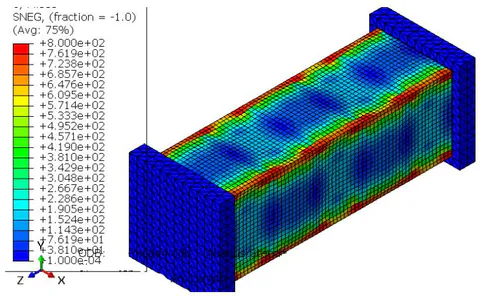
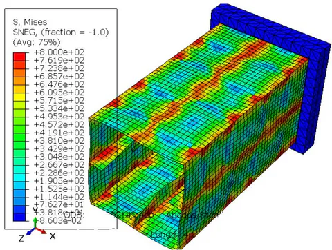
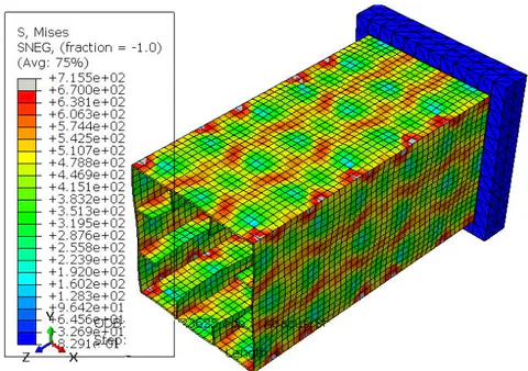
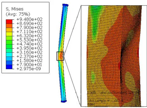
The proposed stiffening system may be improved by arranging the stiffeners properly, which can even change the strain softening properties. The steel tubes' dimensions were selected to provide relatively slender, non-compact, and compact sections. The numerical results for the unstiffened and stiffened steel hollow columns are summarized in Tables 8 and Tables 9, respectively. According this results, the strength of the stiffened steel tube hollow columns is remarkably higher than those of the unstiffened columns ones. The unstiffened and stiffened square steel tube columns primarily collapsed due to local buckling but at different modes, as shown in Figure 28 for US-4, SS-4, and DS-4 specimens, respectively. Figure 24 shows the ultimate strength curves of the US, SS, and the DS sections. The ultimate strength are normalized by dividing by . The stress distributions for the US-2.5, SS-2.5, and DS-2.5 specimens are shown in Figure 22 and Figure (23a and b), respectively. The proposed stiffening method can enhance the steel tube ultimate ductility and strength. The collapsed modes of the steel columns indicate that the stiffening scheme effectively delays local buckling.
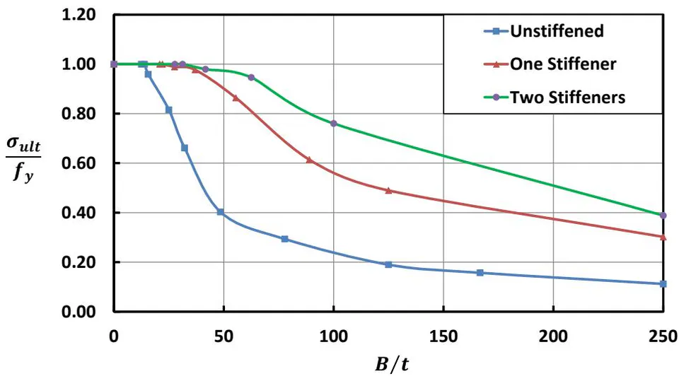
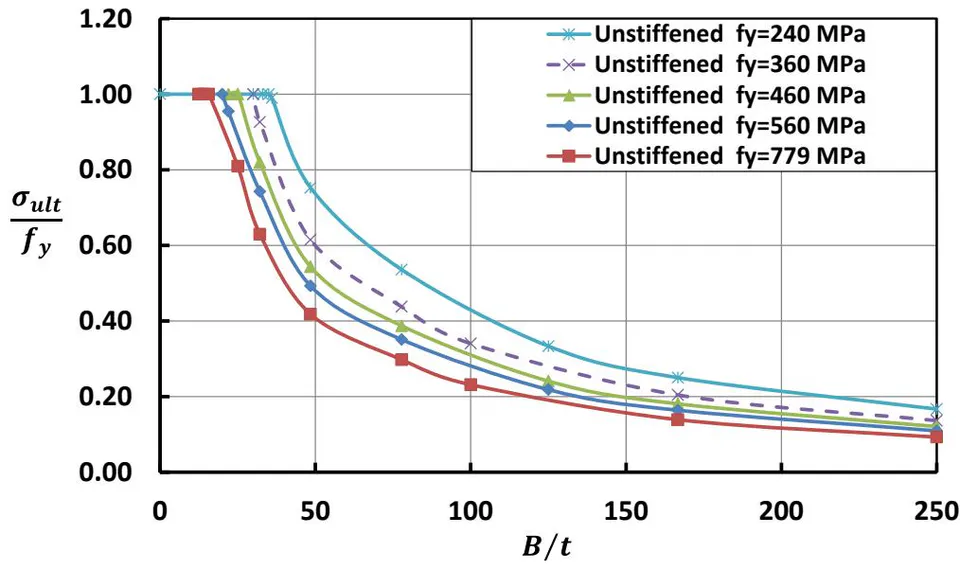
Specimen label (B/t) σUlt/fy atfy(MPa) 240 MPa 360 MPa 460 MPa 560 MPa 779 MPa US-1 250 0.17 0.14 0.12 0.11 0.11 US-1.5 167 0.25 0.20 0.18 0.16 0.16 US-2 125 0.33 0.27 0.24 0.22 0.19 US-3.2 78 0.54 0.44 0.39 0.35 0.29 US-5.1 48 0.75 0.61 0.54 0.49 0.40 US-7.7 32 0.99 0.93 0.82 0.74 0.66 US-10 25 1.00 1.00 1.00 0.95 0.82 US-16 16 1.00 1.00 1.00 1.00 0.96
Table 9: The dimensions and FE results of the stiffened sections with one and two stiffeners, where the stiffeners length
| Specimen label | (B/t) | σUlt/fy at fy (MPa) | ||||
| 240 MPa | 360 MPa | 460 MPa | 560 MPa | 779 MPa | ||
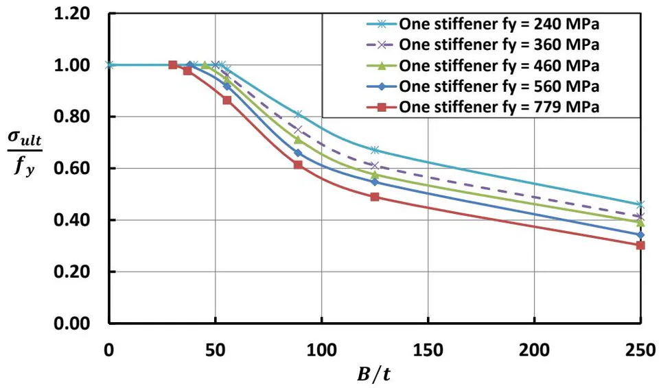
| SS-1 | 250 | 0.46 | 0.41 | 0.39 | 0.34 | 0.3 |
| SS-2 | 125 | 0.67 | 0.61 | 0.58 | 0.55 | 0.49 |
| SS-2.8 | 89 | 0.81 | 0.75 | 0.71 | 0.66 | 0.61 |
| SS-4.5 | 55 | 0.98 | 0.96 | 0.94 | 0.92 | 0.86 |
| SS-6.7 | 37 | 0.99 | 0.98 | 0.96 | 0.99 | 0.98 |
| SS-9 | 28 | 1.00 | 1.00 | 1.00 | 1.00 | 1.00 |
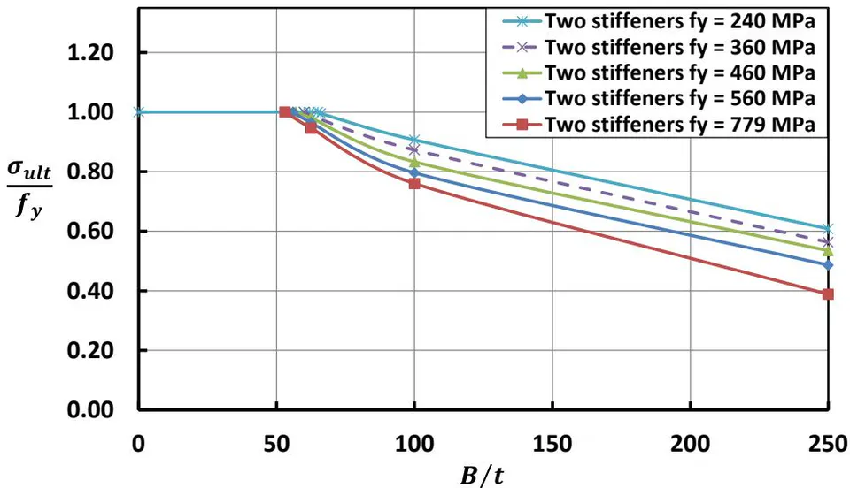
| DS-1 | 250 | 0.61 | 0.56 | 0.53 | 0.49 | 0.39 |
| DS-2.5 | 100 | 0.91 | 0.87 | 0.83 | 0.8 | 0.76 |
| DS-4 | 63 | 1.00 | 0.99 | 0.98 | 0.96 | 0.95 |
| DS-6 | 42 | 1.00 | 1.00 | 0.99 | 0.98 | 0.98 |
| DS-8 | 31 | 1.00 | 1.00 | 1.00 | 1.00 | 1.00 |
iv. Effect of Yield Strength of Hollow Short Steel Columns
In recent years the yield strengths of structural steel have increased. This study aims to determine the influence of the yield strength on the normalized ultimate strength for the stiffened and unstiffened hollow steel columns. The numerical simulations were carried out for yield strength equal to (240, 360, 460, 560, and ). Figures (25, 26, and 27) show the results for the normalized ultimate strength versus the ratio .
v. Failure Modes
For hollow short steel columns, in the linear buckling analysis, we studied a steel tube model that was undamaged and without any significant deformations, but now with non-linear buckling analysis, we will look at how the stiffeners affected on the capacity and buckling load of steel hollow columns. The local buckling mode should be plotted in form of deformation and stress, it is necessary for the mode that results in collapse. This is done to confirm that the buckling response is physical and that the square hollow steel columns have in real collapsed. The ultimate strength and the stress versus strain curve of model is the main output of the non-linear analysis.
Figure 28 shows the buckling modes for the US-4, SS-4, and DS-4 specimens, respectively. The stiffeners can effectively constrain the local buckling of the steel tube. Finally, the buckling of the steel tube is less obvious with the increasing of the number of stiffeners, and the stiffened steel columns have greater serviceability advantages compared to those unstiffened columns.
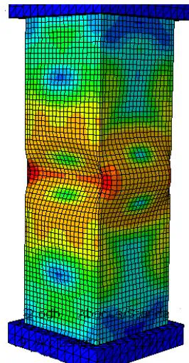
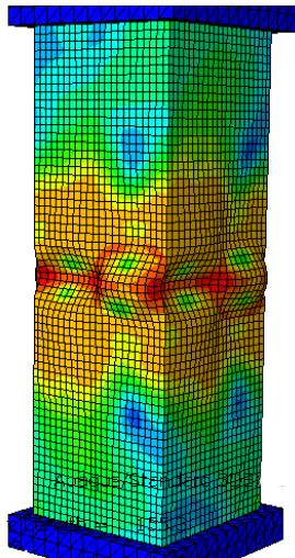
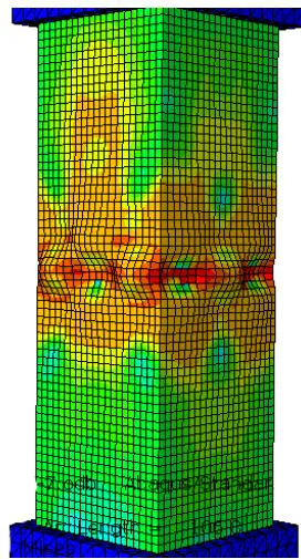
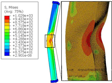
(a) The (US-4) specimen, (b) The (SS-4) specimen, (c) The (DS-4) specimen For long steel columns, the unstiffened compact sections with , width-to thickness ratio , and from 31 to 95 failed mainly due to the effect of global buckling without any local buckling. As well as when , the columns failed due to the full plastic strength, as summarized in Table 13. For the stiffened sections with one stiffener with the tube thickness and the from 44 to 99 collapsed due to the global buckling only without any local buckling. As well as when the columns failed due to the full plastic strength, as summarized in Table 12. The numerical specimens for unstiffened sections with width-to thickness ratio and from 30 to 80 failed by both of global and local buckling (G and L) as summarized in Table 14. In addition, these columns failed due to the global buckling when . For stiffened sections with one stiffener, when the columns with and failed by predominantly local buckling (L). As well as these columns failed due transforms into a combination of the global and local buckling (L and G) when the , as summarized in Table 15. The buckling mode for the (US-5-4000) and (US-5-7000) specimens is shown in Figure 32 and Figure 33, respectively.
vi. Effect of the Stiffener Length for Short Columns
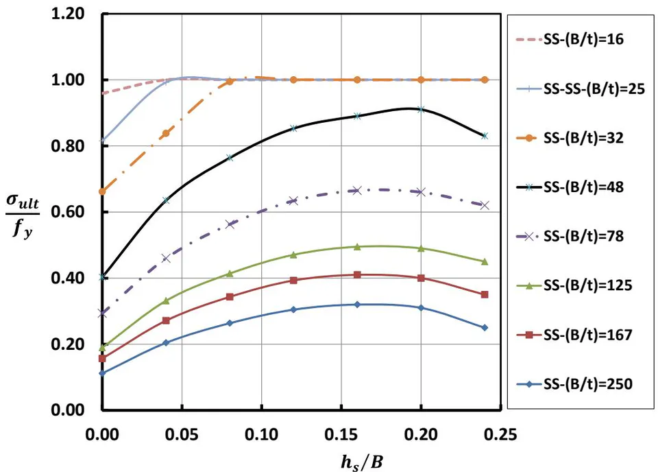
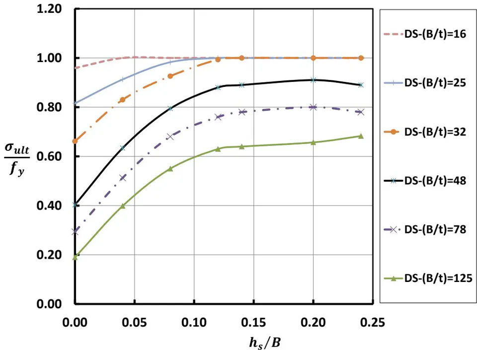
The effect of stiffener length on the stiffened sections with one and two stiffeners is shown in Figure 29 and Figure 30. The optimum stiffener length at different tube thickness is calculated using Eq. (17) and Eq. (18) for the stiffened columns with one (SS) and two (DS) stiffeners, respectively. The ratio, the ratio, and the finite element normalized stress results are shown in Table 10 and Table 11.
| B/t | hs/B | |||||
| 0.04 | 0.08 | 0.12 | 0.16 | 0.2 | 0.24 | |
| σUlt/fy | ||||||
| 250 | 0.20 | 0.26 | 0.30 | 0.32 | 0.31 | 0.25 |
| 167 | 0.27 | 0.34 | 0.39 | 0.41 | 0.40 | 0.35 |
| 125 | 0.33 | 0.41 | 0.47 | 0.50 | 0.49 | 0.45 |
| 78 | 0.46 | 0.56 | 0.63 | 0.67 | 0.66 | 0.62 |
| 48 | 0.63 | 0.76 | 0.85 | 0.89 | 0.91 | 0.83 |
| 32 | 0.84 | 0.99 | 1.00 | 1.00 | 1.00 | 1.00 |
| 25 | 0.99 | 1.00 | 1.00 | 1.00 | 1.00 | 1.00 |
| 16 | 1.00 | 1.00 | 1.00 | 1.00 | 1.00 | 1.00 |
(B/t) hs/B 0.04 0.08 0.12 0.16 0.2 0.24 σUlt/fy 125 0.40 0.55 0.63 0.64 0.66 0.68 78 0.51 0.68 0.76 0.78 0.80 0.78 48 0.63 0.79 0.88 0.89 0.91 0.89 32 0.83 0.93 0.99 1.00 1.00 1.00 25 0.91 0.98 1.00 1.00 1.00 1.00 16 0.96 1.00 1.00 1.00 1.00 1.00
vii. The Stiffeners' Effect on Long Columns
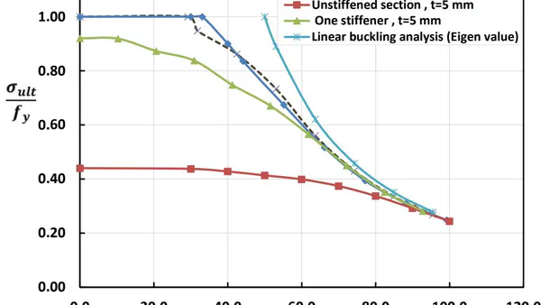
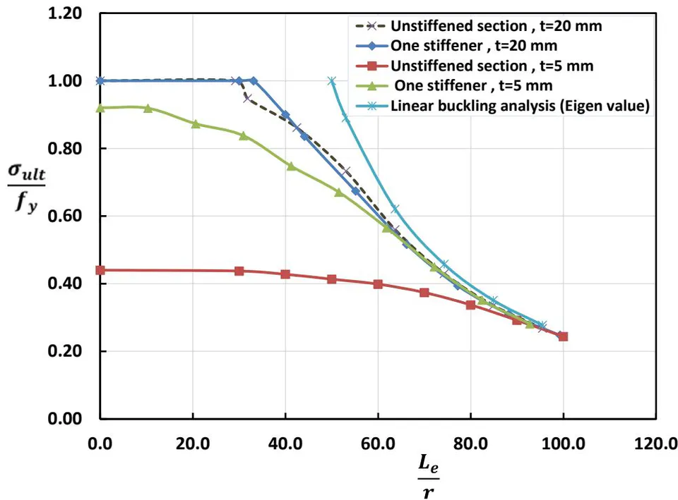
Figure 31 shows the comparison between normalized ultimate strength (( / f_y)) for the stiffened and unstiffened sections obtained from FEA results, where the tube thickness (t = 20 , ) and (t = 5 , ). The measured normalized ultimate strength (( / f_y)) for these columns is summarized in Tables (12 to 15). For the compact unstiffened sections when (t = 20 , ) and (KL_e/r \leq 29), ( / f_y = 1) this means that the steel columns mainly collapsed due to the full plastic strength. In addition, when (KL_e/r > 29) the ( / f_y < 1) this means that the steel columns mainly failed due to global buckling. Similarly, for stiffened sections with one stiffener when (t = 20 , ) and (KL_e/r \leq 33), the ( /
this means the columns failed due to the full plastic strength. In addition, when the this means the columns failed due to global buckling. The ultimate strength curves for the stiffened and unstiffened sections, when are very close. In case of the slender sections when the measured normalized ultimate strength equal to 0.43 and 0.92 for unstiffened and stiffened short columns, respectively. The ultimate strength curve for stiffened sections higher than unstiffened sections for all values as shown in Figure 31. According to this study, the stiffeners greatly affect the ultimate strength of slender sections in the long columns.
| No. | Specimen label | B/t | KL_e/r | σultfy | Buckling mode |
| 1 | SS-20-3000 | 12.5 | 33.1 | 1.00 | Plastic |
| 2 | SS-20-4000 | 12.5 | 44.1 | 0.84 | Global |
| 3 | SS-20-5000 | 12.5 | 55.1 | 0.67 | Global |
| 4 | SS-20-6000 | 12.5 | 66.2 | 0.52 | Global |
| 5 | SS-20-7000 | 12.5 | 77.2 | 0.39 | Global |
| 6 | SS-20-8000 | 12.5 | 88.2 | 0.31 | Global |
| 7 | SS-20-9000 | 12.5 | 99.2 | 0.25 | Global |
Table 13: The dimensions and FE results of the unstiffened sections, where the ratio
| No. | Specimen label | B/t | KLer/r | σultfy | Buckling mode |
| 1 | US-20-2750 | 12.5 | 29.2 | 1.00 | Plastic |
| 2 | US-20-3000 | 12.5 | 31.8 | 0.95 | Global |
| 3 | US-20-4000 | 12.5 | 42.4 | 0.86 | Global |
| 4 | US-20-5000 | 12.5 | 53 | 0.73 | Global |
| 5 | US-20-6000 | 12.5 | 63.7 | 0.56 | Global |
| 6 | US-20-7000 | 12.5 | 74.3 | 0.43 | Global |
| 7 | US-20-8000 | 12.5 | 84.9 | 0.34 | Global |
Table 14: The dimensions and FE results of the unstiffened sections, where the ratio
| No. | Specimen label | B/t | KLr | σultfy | Buckling mode |
| 1 | US-5-3000 | 50 | 30 | 0.43 | Local |
| 2 | US-5-4000 | 50 | 40 | 0.42 | L+G |
| 3 | US-5-5000 | 50 | 50 | 0.41 | L+G |
| 4 | US-5-6000 | 50 | 60 | 0.39 | L+G |
| 5 | US-5-7000 | 50 | 70 | 0.37 | L+G |
| 6 | US-5-8000 | 50 | 80 | 0.33 | L+G |
| 7 | US-5-9000 | 50 | 90 | 0.29 | Global |
Table 15: The dimensions and FE results of the stiffened sections with one stiffener, where the ratio
| No. | Specimen label | B/t | KLer/r | σultfy | Buckling mode |
| 1 | SS-5-1000 | 50 | 10.3 | 0.92 | Local |
| 2 | SS-5-2000 | 50 | 20.6 | 0.87 | Local |
| 3 | SS-5-3000 | 50 | 30.9 | 0.84 | Local |
| 4 | SS-5-4000 | 50 | 41.2 | 0.75 | L+G |
| 5 | SS-5-5000 | 50 | 51.5 | 0.67 | L+G |
| 6 | SS-5-6000 | 50 | 61.8 | 0.57 | Global |
| 7 | SS-5-7000 | 50 | 72.1 | 0.45 | Global |
| 8 | SS-5-8000 | 50 | 82.4 | 0.35 | Global |
V. DEVELOPMENT OF NOVEL ANALYTICAL EQUATIONS
As a major result of the conducted analysis, novel equations to calculate the steel tube ultimate strength with either one or two stiffeners was presented. The proposed equations were deduced from the parametric study using data regression analysis. The strength ratio , for hollow square sections stiffened with one stiffener can be calculated using Eq. (19). The and are strength reduction factors according to the yield strength and stiffeners length, respectively. The values of and are determined from the parametric study, as shown in Figure 29 and Figure 26.
Where;
The reduction factors can be calculated as follows:
Furthermore, the strength ratio, , for hollow steel sections stiffened with two stiffeners can be calculated using Eq. (22). Where and are strength reduction factors according to the yield strength and stiffeners length, respectively. The value of and are determined from the parametric study, as shown in Figure 30 and Figure 27.
Where
The reduction factors can be calculated as follows:
If can be calculated as follows
And when
VI. CONCLUSIONS
This research aims to predict the behavior of hollow steel columns under monotonic loads and determine the effect of the main parameters on ultimate strength capacity. based on the study of verification, A parametric investigation was carried out to create three-dimensional finite element models that simulate the stiffened and unstiffened hollow steel columns under axial compression loads. These models focused on both the local and global buckling and were divided into two cases. Case 1, study effect of the local buckling on the ultimate strength and behavior for stiffened and unstiffened hollow steel short columns. Case 2, study the stiffeners' effect on the steel tube ultimate strength for long columns. The non-linear finite element (FE) analysis is used in the study to understand the effect of main structural parameters such as , stiffener length, the ratio of width-to-thickness , and the yield stress on the hollow steel column performance. The conclusions that can be drawn are as follows:
The simulation of the behavior of hollow square columns using (FE) analysis can be done with about grade of accuracy. in addition to this, the (FE) analysis can reduce cost and time when compared with experimental work. The idealized elastic-plastic material model of the steel tube and the actual material models, as well as the actual initial imperfections and manufacturing errors in the real connections employed in experimental studies, were the main causes of the insignificant variations between the FEA results and experimental testing.
The study was conducted on the effect of the stiffeners length and proposed a novel equation to calculate the optimal stiffeners length in case of stiffened sections with one stiffener (SS) and stiffened sections with two stiffeners (DS) for short columns.
When increasing the width-to-thickness ratio of stiffeners about the optimum stiffener length, the value of decreases due to local buckling of the stiffener.
The current FE model produces good predictions of the steel box columns ultimate strength compared with the analytical methods. For the unstiffened steel tube columns, the average variation in the ultimate strength depending on the results from the present FE models and the effective width method by Uy[24] is about . Furthermore, the average variation in the ultimate strength obtained from present FE models and the modified (DSM) is about
6%. While for stiffened columns, the average variation is around between current FE models and the effective width method by Norsok. Thus, it can be concluded that the proposed method can accurately predict the ultimate load capacity of short columns.
As a major result of the conducted analysis, a novel equation to calculate the ultimate strength of box steel sections with one and two stiffeners was presented.
The presence of the stiffeners remarkably increases the ultimate strength of slender sections in the long columns. But on the other hand, it has no effect on the ultimate strength of compact sections.
The unstiffened columns with the ratio of width to thickness and from 30 to 80 collapsed as a consequence of the combination of global and local buckling (G and L). In addition, these columns collapsed according to the global buckling when . For stiffened sections with one stiffener, when the columns with and collapsed by the local buckling only (L). In addition, these columns collapsed as a consequence of the combination of global and local buckling (G and L) when the .