

I. INTRODUCTION
The load frequency control problem discussed so far does not consider the effect of the restrictions on the rate of change of power generation. In power systems having steam plants, power generation can change only at a specified maximum rate. The generation rate for reheat units is quite low. Several methods have been proposed to consider the effect of GRC. The system dynamic model becomes non-linear and linear control techniques cannot be applied for the optimization of the controller setting.
Load frequency control (LFC) performs a very important role in power stability between load and generation sides. In the latest years, many robust design strategies have been delivered for LFC[1-3] the dynamic behaviour of the many industrial plants are heavily influenced by means of disturbances and, in particular, by adjustments in the operating point. This is often sometimes typically the case for power systems [4]. Automatic Generation Control (AGC) is the most necessary problems in electric strength machine sketch and operation. The goal of the AGC in an interconnected strength machine is to hold tie-line electricity strength and to keep the frequency of every area shut to the scheduled values through adjusting the MW outputs of the AGC generators which will accommodate fluctuating load demands [5]. The generator excitation device keeps the generator voltage and controls the reactive electricity flow. A generator excitation of the older system may additionally be furnished via slip rings and brushes via implying of DC generator hooked up on the equal shaft as the rotor of the synchronous motor [6].
Obviously, trade in the real electricity demand impacts if truth be told the frequency, whereas a change in the actual strength influences by the voltage magnitude. The communication between frequency control and voltage is typically weak enough to justify their analysis separately. The sources of reactive strength are generators, capacitors, and reactors [7].
Generators with identical response characteristics for load variations assembled together to meet a particular load demand is referred to as the area. These areas are interconnected with tie lines these tie lines are used to alternate energy between areas, which will increase fault level and inter-area support just in case of abnormal situations . The area may also have mixed of various sources combination of different sources in this paper every area consists of thermal with reheat type turbine system, fuel electricity technology hydro, gas power generation . The conventional control approach for the frequency regulation problem is based totally on applying corrective signal governor summing point using PI, PID controllers. These controllers achieve zero steady-state error however dynamic performance exhibited by these controllers may be very poor. Greater over PI, PID controllers fail to provide satisfactory performance over a variety of operating conditions.
A literature review on LFC shows varied control strategies have been utilized for the load frequency control problem. Optimal state feedback control approaches, sub-optimal state feedback controllers are projected in Adaptive and self-tuning methods are proposed in Evolutionary algorithms like GA, PSO, optimization, bacterial foraging, etc. applied by several authors . In an extensive literature survey, LFC shows that LFC with ANN & Fuzzy logic control application providing better performance for load frequency control problems .
II. AUTOMATIC GENERATION CONTROL
The first procedure in the analysis and design of a control system is the construction of mathematical modelling of the system. The two most common methods are the transfer function method and the state variable approach. The state variable methodology can be applied to model linear as well as nonlinear systems. So as to use the transfer function and linear state equations, the system initially is linearized appropriate assumptions and approximations are made to linearize the mathematical equations describing the system. A transfer function model is obtained for the following components.
a) Generator Load Model
Gives the relation between the changes in frequency ( ) as a change by a small amount ( ). Neglecting the change in generation losses,
TPS is a power system time constant
KPS is a power system gain
b) Prime Mover Model
he model for the turbine relates modifications in mechanical power output to modifications in steam valve position, the simplest prime mover model for the non-reheat steam turbine can be approximated with a single time constant (Tt), resulting in the following transfer function:
c) Speed Governor Model
Most modem governors use electronic means to sense speed changes.
R = Speed regulation of the governor
KSg = Gain of speed governor
Tg (s) = Time constant of speed governor
III. AREA CONTROL ERROR OF TWO AREAS
The normal switch characteristic of the mannequin is Let us now flip our attention to ACE (area control error) in the presence of a tie line. In the case of an isolated manage area, ACE is the exchange in place frequency which when used in crucial manage loop forces the steady country frequency error to zero. In order that the regular country tie line strength error in a two-area manipulate be made zero every other control loop (one for every area) has to be brought to combine the incremental tie line strength signal and feed it lower back to velocity changer. This is performed by using a single line-integrating block through redefining ACE as a linear combination of incremental frequency and tie-line power.
IV. AUTOMATIC VOLTAGE REGULATOR
AVR is an important part of a synchronous generator. The AVR is used for regulating the terminal voltage of the synchronous generator. Whenever, there is an unexpected drop in voltage due to accidents, faults or common changes in loading. The AVR improves the transient stability of a system.
a) Amplifier Model
The comparator continuously compares the reference voltage Vref and actual output voltage Vt and generates voltage error signal, which is fed to the amplifier. The amplifier can be magnetic, rotational or electronic type. Due to the delay in the response of the amplifier, its transfer function (T. FA) is given by:
Where (S) is the amplifier output and (S) is the error voltage and is given by:
b) Exciter
In the simplest form, the transfer function of the modern exciter may be represented by the single time constant TE and gain KE,
Where (S) is the field voltage of the synchronous generator, the time constant of the modern exciter is very small.
c) Generator Field Model
The synchronous machine generated EMF is a function of the magnetization curve, and it's terminal voltage is dependent on the generator load.
d) Sensor Model
The sensor sensed voltage through a potential transformer.
V. SIMULATION AND RESULTS
The design and simulation of the system are analysing using MATLAB SIMULINK environment. And it's using it to testing the individual blocks of automatic voltage control and automatic voltage regulator system of single and two areas with generation rate constraint and used area control error to improve the dynamic response and to reduce the steady-state error to zero.
In this study there are many assumptions, the model of thermal generation plant, also the system with two control areas that had one tie line between them and the basic block diagram for a single and two areas AGC, the system is in a normal operating mode and the loss of a generating unit will not be considered.
a) Two Areas Load Frequency Control
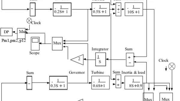
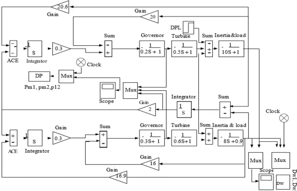
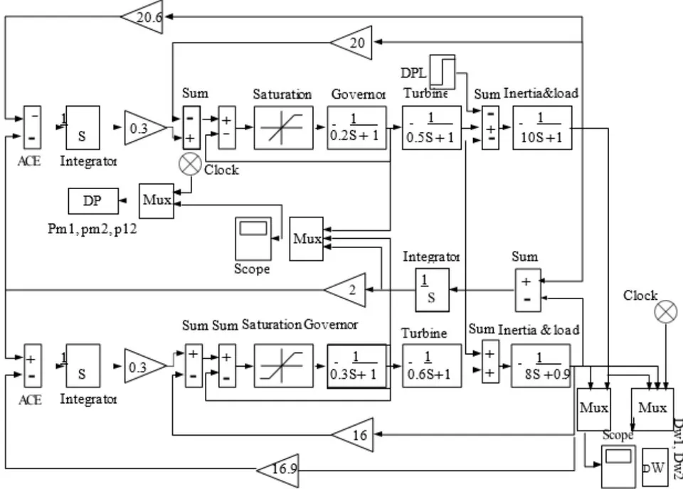
Figure 1 represented the simulation of the block diagram of two areas.
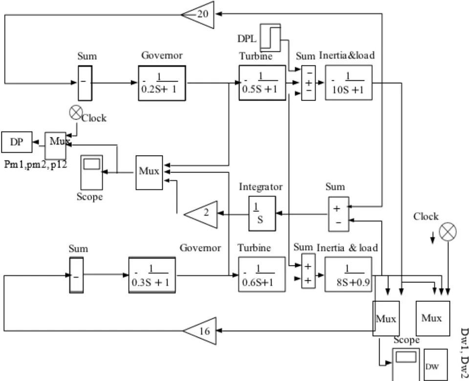
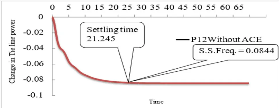
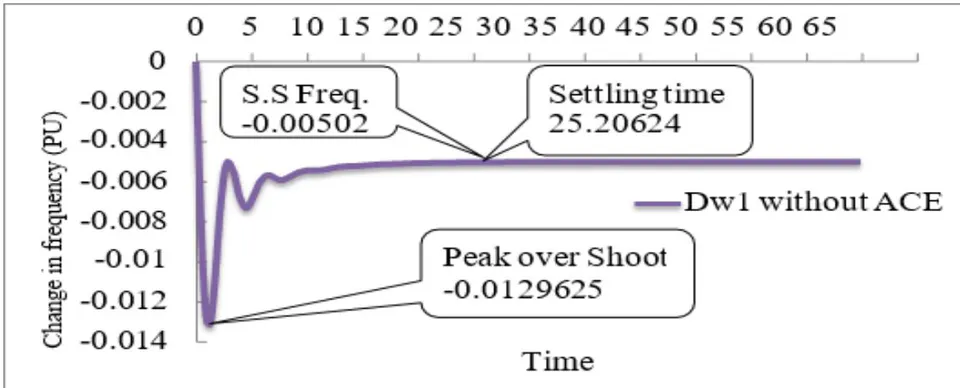
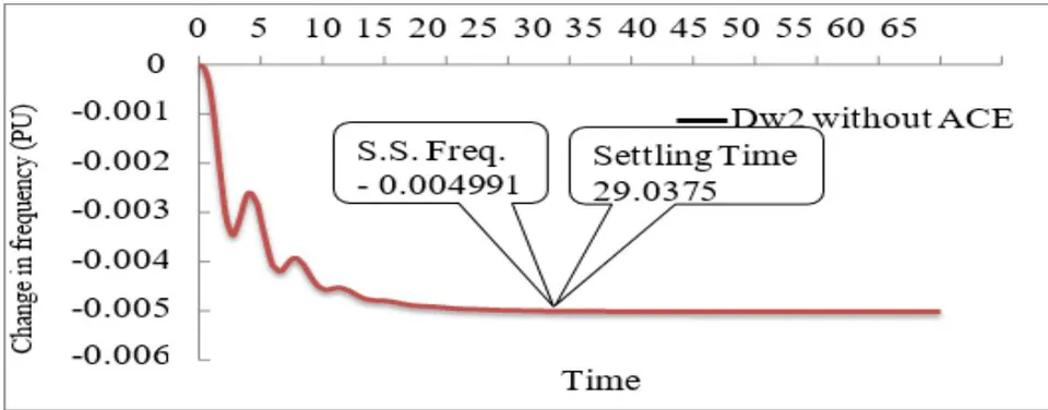
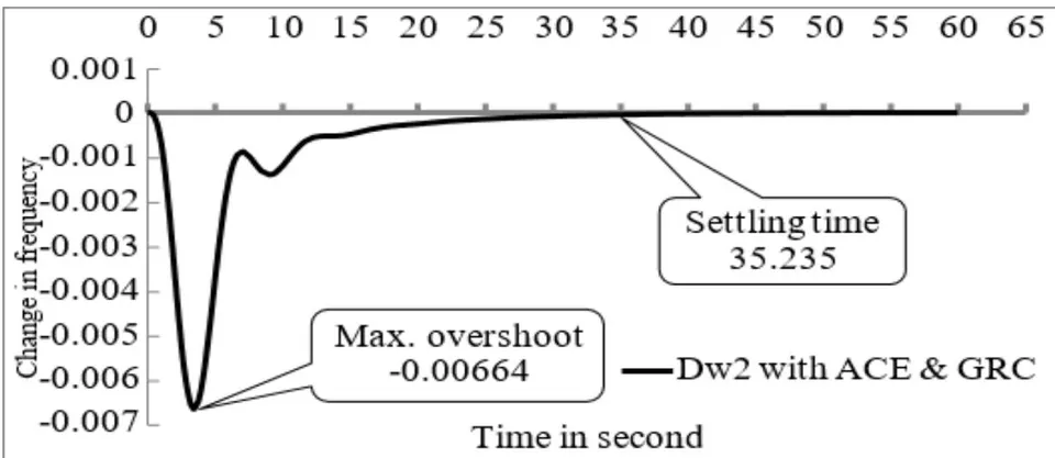
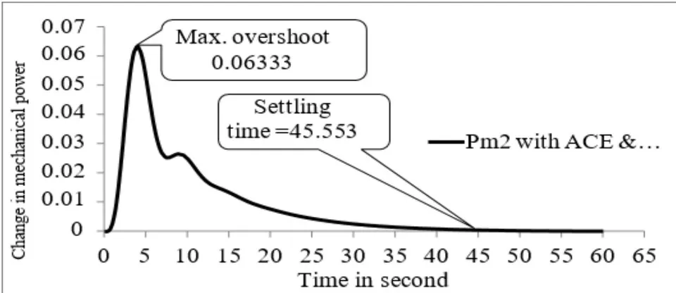
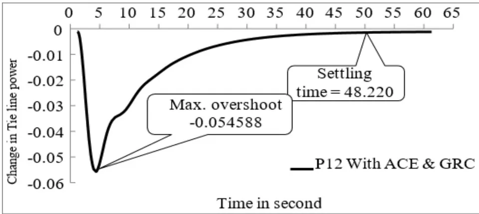
Figure 4 shows the schematic of the LFC of the 2-area system without the secondary loop while figures 2, 3, 4 shows the simulation results. As the two systems are interconnected, the frequency drifts of the two will settle down to equal value after some oscillations. The mechanical inputs of the two vary to reduce the mismatched power between the electrical load in area 1 and the mechanical inputs. It can also be observed that area 2 will generate excess power to share the load change in area1. It can observe the tie-line power flow following a load disturbance in area 1. Compared to the same result with the system, I appreciated the stability improvement with interconnection.
b) Two Areas Load Frequency Control with Area Control Error
The tie line deviation reflects the contribution of the regulation characteristic of one area to another. The basic objective of supplementary control is to restore the balance between each area load generation. This objective is met when the control action maintains frequency at the scheduled value. The supplementary control should ideally correct only for changes in that area. In other words, if there is a load change in Area1, there should be supplementary control only in Area1 and not in Area2. For this purpose, the area control error (ACE) is used.
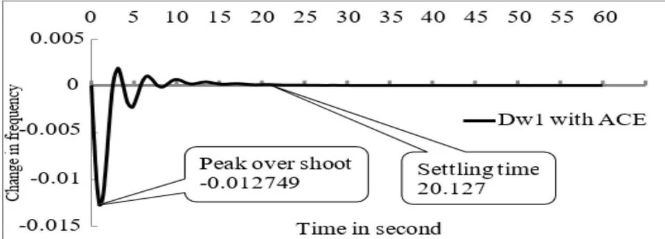
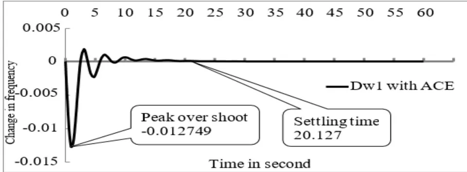
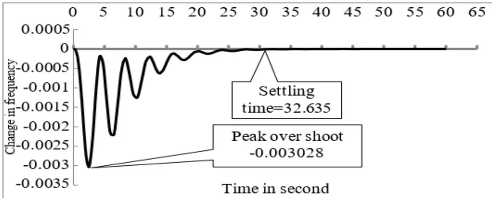
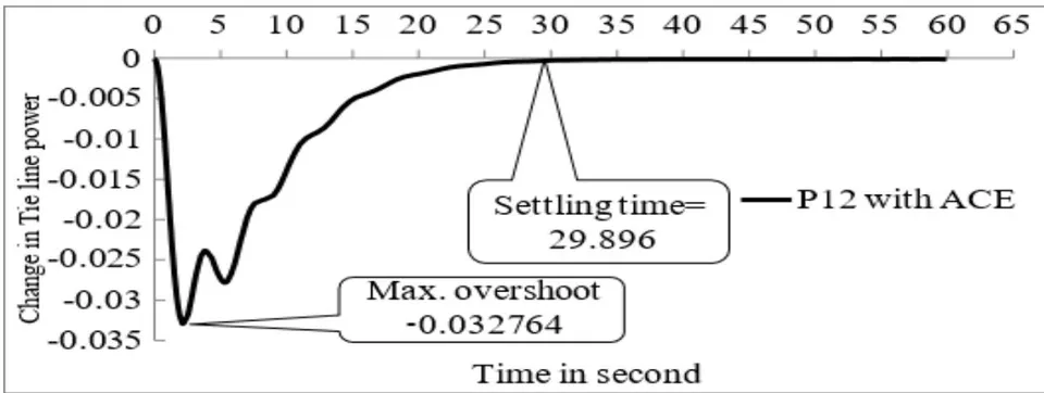
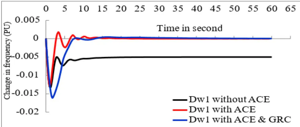
As seen from the figures the secondary loop causes the return of frequency drifts to zero.
From the above simulation plots, it can be observed that the system experiences frequency drift following a load disturbance and it is mainly due to the mismatch between the electrical load and the mechanical input to the turbine. The system oscillation is serious in single area system compared to two area system because all the load change in load is to be met by only one area. Also, using the second loop in both the single area as well as the two area system the change in frequency is brought to zero.
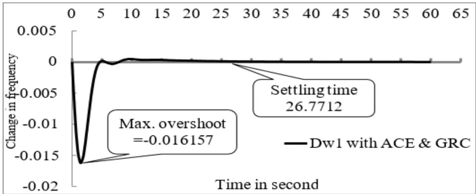
c) Two Areas Load Frequency Control with Generation Rate Constraint
| Peak over shoot | S.S.Freq. | Settling time | |
| First order | -0.01296 | -0.00502 | 25.20624 |
| Without ACE | -0.012749 | 0.0 | 20.1273 |
| With ACE | -0.016157 | 0.0 | 26.7712 |
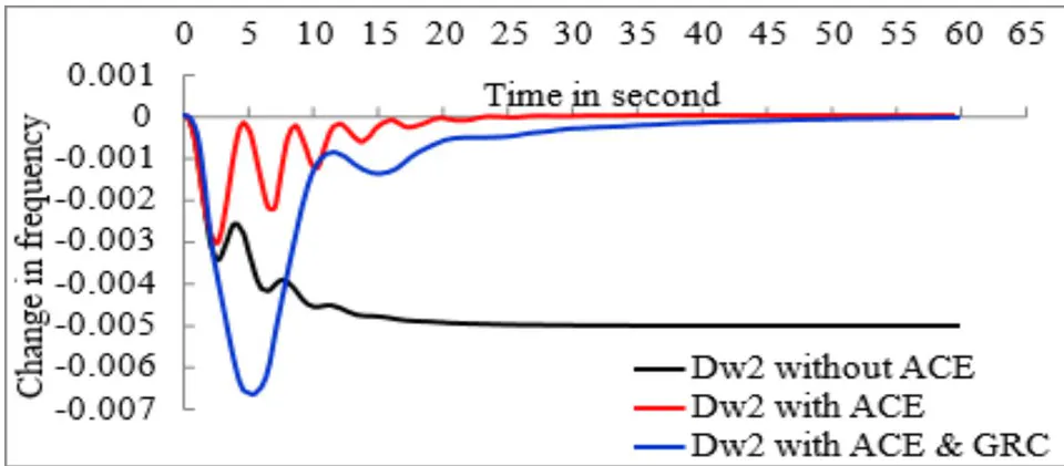
| Peak over shoot | S.S.Freq. | Settling time | |
| Without ACE | -0.004991 | -0.004991 | 29.037 |
| With ACE | -0.003028 | 0.0 | 32.635 |
| With GRC | -0.00664 | 0.0 | 35.235 |
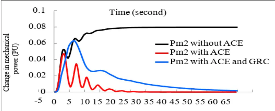
| Peak over shoot | S.S.Freq. | Settling time | |
| Without ACE | 0.07996 | 0.07996 | 25.206 |
| With ACE | 0.04721 | 0.0 | 32.452 |
| With GRC | 0.06333 | 0.0 | 45.553 |
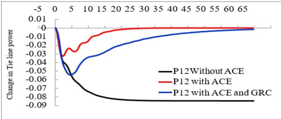
| Peak over shoot | S.S.Freq. | Settling time | |
| Without ACE | -0.0844 | -0.0844 | 21.245 |
| With ACE | -0.0327 | 0.0 | 29.896 |
| With GRC | -0.0546 | 0.0 | 48.220 |
Automatic Generation Control was implemented in the system under study in a deregulated environment. The effect of GRC is clearly distinct with large oscillations the system overshoots increase and more settling time.
The main reason to consider GRC is that the rapid power increase would draw out excessive steam from the boiler system to cause steam condensation due to adiabatic expansion. Since the temperature and pressure in the HP turbine are normally very high with some margin, it is expected that the steam condensation would not occur with about 20% steam flow change unless the boiler steam pressure itself does not drop below a certain level. Thus it is possible to increase generation power up to about 1.2 pu of normal power during the first tens of seconds. After the generation power has reached this marginal upper bound, the power increase of the turbine should be restricted by the GRC. GRC affecting large turbo generator is generally bounded by 0.1/min. As the constraint of the generator and that of control effort calculated in LFC are in direct proportions, GRC will be transformed into system control constraints.
VI. CONCLUSION
A simulation study of two area systems with automatic generation control is carried out with models developed in SIMULINK. The simulation of these systems has been carried out and results analyzed. The operation of two area systems with and without automatic voltage regulator are very well depicted through simulation models. The advantage of interconnection is best understood by comparing the results of two area systems. It can be seen that the oscillations due to the change in load in any area are damped down quickly because of tie-line power flow. It can also be observed that the dynamic response is mainly governed by the secondary loop and hence design criteria of which is extremely vital for efficient implementation.
The frequency of the system is dependent on real power output and is taken care of by ALFC. The terminal voltage of the system is dependent on the reactive power of the system and is taken care of by the AVR loop. The cross-coupling effects between the two loops are studied which is associated with low-frequency oscillations. It is clear from the results that the AVR loop is able to maintain the voltage and frequency deviations in the specified limits and the power system thus becomes more robust. The dynamic responses are further improved in terms of peak deviations and settling time.