## I. INTRODUCTION
In 1780 Italian biologist and physicist Luigi Galvani and his wife, Lucia, discovered that the muscles of dead frogs' legs twitched when struck by an electrical spark [1]. Now regulation of a cell, tissue, and organ-level behavior as the result of electrically mediated signaling is called bioelectricity. It is based on ion fluxes through biological membranes, and in equilibrium transmembrane electric potential difference $\Delta E$ for an ideally ion-selective membrane is described by Nernst equation
$$
Here c₁ and c₂ are concentrations \Delta E = - \frac {2 . 3 R T}{z F} \log \frac {c _ {2}}{c _ {1}} \tag {1}
$$
Here $c_{1}$ and $c_{2}$ are concentrations of the permeable ion in two separated by the membrane solutions. The coefficient $2.3RT / zF$ for monocharged cations $(z = +1)$ at room temperature is near $60\mathrm{mV}$, and transmembrane voltage through biological membranes for 100-fold ratio $c_{1} / c_{2}$ is near $120\mathrm{mV}$. Nevertheless, the stack of many membranes in an electric organ of South American electric eels may generate remarkably high voltage. For example, the recently discovered strongest bioelectricity generator Electrophorus voltaic (named after Volta!) generates up to $860\mathrm{V}$, but the duration of the discharge is only $1.7\mathrm{ms}$ [2].
Alessandro Volta realized that the frog's leg served both as a conductor and as a detector of electricity. He also understood that the frog's legs twitching may be caused by the two different metals connected one with another and with a frog leg. When he replaced the frog's leg with a brine-soaked paper or cardboard, he detected the flow of electricity. Later, as a result of a professional disagreement over advocated by Galvani mechanism, in 1800 Volta invented the first electric battery, now known as a voltaic pile. Its original may be found in the Volta temple in Como, near Milan. Volta also demonstrated that an effective and easily available pair of dissimilar metals to produce electricity was zinc and copper [3].
In physical terms, we say that two dissimilar metals have different Fermi levels of their electrons. In electrochemistry we use the misleading term Galvani potential to describe the electric potential difference between two points in the bulk of two metals. This difference leads to redox half-reactions on the metal surfaces in contact with brine. Zinc, as a more active metal, becomes partially dissolved in the acidic electrolyte solution as an oxidized form $\mathrm{Zn}^{2+}$. If both metals are separated in space but connected outside the electrochemical system via wires, the released electrons are transferred to a less active metal, such as Cu. $\mathrm{Cu}^{2+}$ in a solution serves as an oxidant, converting into metal and taking electrons. Separated in space metals in this case are called electrodes. Zn electrode is called an anode, and $\mathrm{Cu}^{2+}$ electrode is a cathode. Formation of cations near the anode and disappearance near the cathode leads to the redistribution of ions in the brine, i.e., to the ionic current in the aqueous electrolyte.
In a homogeneous solution electron-transfer reactions between mixed redox components do not lead to an electric current. Volta's genius was that he separated the half-reactions in space, but they are still connected via ion transport in the electrolyte and electron transport outside the electrochemical cell. Since Volta's pile, all electrochemical batteries have a series of electrochemical cells. Two electrodes in each cell are separated by ionic electrolyte, but they are also connected to electrodes in the neighboring cells. Each of them serves as a source of energy, providing an elementary voltage in the battery. Later it was suggested to use ion-exchange membranes as separators inside the electrochemical cell, so that electrolyte solutions in contact with the anode and cathode may have different compositions, including pH optimized for each of the half redox reactions.
In the open circuit, initial transfer of electrons leads to charge separation. The difference of chemical properties (more accurately, the difference of redox potentials) of electrodes leads to voltage generation between two electrodes. After that new electron cannot be transferred against electric potential difference, but if the whole cycle is not broken anywhere (closed circuit), also the continuous electric current, carried by electrons outside the electrochemical cells and by ions inside the cells, is observed.
Voltage generation using electrode-based systems has a serious advantage in comparison to the situation with biological membranes because it is based on redox reactions of different species. The Nernst equation now includes the difference of standard redox potentials $\Delta E_0$ between an oxidant and reducing agent. The standard redox potentials in aqueous solutions are for semireactions $Zn^{2+} + 2e^{-} = Zn(s)$, $E_0 = -0.76V$ and $Cu^{2+} + 2e^{-} = Cu(s)$, $E_0 = +0.337V$, so that $\Delta E_0 = 1.1V$. The Nernst equation now becomes
$$
\Delta E = \Delta E _ {0} - \frac{2 . 3 R T}{z F} \log \frac{c _ {o 1} c _ {r 2}}{c _ {r 1} c _ {o 2}} \tag{2}
$$
Biological membrane-based "electrochemical cells" give much lower voltage, but they do not have metal-based electrodes. Their advantages are smaller size, smaller weight, possibility to work at neutral pH, etc. It seems attractive to develop not an ion-selective, but an electron-selective membrane. Well-known bilayer lipid membranes, used as a model of biological membranes, are not good for this purpose at least because they have very high specific electric resistance $(\sim M\Omega \times cm)$ [4]. Previously developed by us biomimetic membrane, which is a simple nitrocellulose filter impregnated by long-chain fatty acids or their esters, is better because even without proteins it has spontaneously formed aqueous nanochannels, lower electric resistance, and ionic selectivity [5]. Mobile quinones can transfer electrons through these membranes, but this redox process is electrically silent and there is no charge separation because of the co-transport of $\mathsf{H}^+$ -ions. As a result, the chemical reaction between two non-mixed substances does not stop [6]. The reaction products are also separated. Potentially it should make further production and purification of redox products much simpler, which is a biological principle known as membrane-based compartmentalization, but it does not lead to essential transmembrane voltage.
Later we used dense membranes made of $\mathsf{H}^+$ -doped polyaniline, known as synthetic metal [7]. In this case, it was possible to observe an electrogenic electron transport from ascorbic acid to the separated by the membrane ferricyanide. Transmembrane electric potential difference was formed, and in optimal conditions without permeating $\mathsf{Cl^-}$ it was described by the ideal Nernst equation [8]. In the presence of high $\mathsf{Cl^-}$ concentration the process was electrically silent, and no transmembrane voltage was formed. Instead, we had coupled counter-transport of electrons in exchange for chloride.
Though these membranes are easy to make and have low resistance, they are brittle. To make a system attractive for practical applications we tried simple metal foils separating in a chamber two aqueous solutions with different redox pairs and discovered that the foils behave like polyaniline membranes, i.e., they serve as membranes, ideally selective for electrons.
The purpose of this paper is to describe a new voltage-generating system based on metal foils and membrane biomimetic ideas. It does not have traditional anode and cathode, but instead of two electrodes and an ion-conducting solution between them it gives redox-based voltage through a not brittle metal foil separating two redox-active aqueous solutions. As a result, a new type of flow-through battery is suggested, where electrochemical cells in the battery are connected by ion-conducting membranes and not by external wires. The battery has low electric resistance and continuously gives reasonable current, which is different to biological membranes with protein-based ionic channels fluctuating between open and close states with characteristic time in a ms range.
## II. MATERIALS AND METHODS
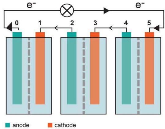
The battery was assembled as a series of flowthrough compartments separated by foils and ion-exchange membranes. Each compartment with the foil on one side and ion-exchange Nafion membrane on another side had an inlet and outlet tubes, so that both reducing and oxidizing solutions may be easily renewed, as it is done in redox-flow batteries (Figures 1, 2). Thus, each combination ion-exchange membrane/ solution 1/foil/ solution 2 /ion-exchange membrane forms a new type of electrochemical cell. To increase the ionic conductivity of the system aqueous solutions had 0.1M or 1M KCl. Ion-exchange membranes have two functions. They separate one cell from another, but simultaneously act as classical salt bridges providing due to ion permeability an electric connection between these cells. In aqueous solutions instead of expensive Nafion membrane we could use ion-exchange membranes Fumasep. The complete system was fixed by screws between two plastic plates.
The total voltage generated by the battery was measured between two covered by Ag/AgCl current collector plates, one in the very first and another - in the very last compartments. Current collectors are a pair of similar electrodes of the second kind with the equilibrium potential being a function of the concentration of an anion in the solution. These pairs do not necessarily lead to additional changes in an open circuit voltage. Instead, they convert ionic current in compartments into an electron-based current outside the battery and are also used for connection to the external load.
The essential difference between metal foils and electrodes is that the foils are not connected by a wire one to another or to anything outside the electrochemical cell. The construction of an assembled battery allowed measuring not only electric potential difference between Ag/AgCl current collector electrodes in different solutions, but also the potential difference between a foil with a free tongue and a reference electrode. To do this the inlet and outlet tubes in each cell related to the capillary Ag/AgCl reference electrodes.
## III. RESULTS
When one foil separates two compartments with different redox solutions, it is possible to observe the difference in electric potentials between these solutions. This was demonstrated with different metal foils, including Cu, stainless steel, and Ag-plated Ni foils. Oxidants were ferricyanide, ceric (+4) ammonium nitrate, and hypochlorite. Reducing agents were ferrocyanide, sodium thiosulfate, and hydrazine in 0.1M KOH. In all cases, the difference of electric potentials in the oxidant solution versus the reducing solution was negative, as it should be according to the direction of electron transport through the foil from the electron donor to the acceptor.
A more detailed description of an experiment with a redox system hydrazine and hypochlorite $\mathrm{ClO}^{-}$ will make the difference with traditional systems more evident. Hydrazine reaction in alkaline media is $N_{2}H_{2} + 4OH^{-}\rightarrow N_{2} + 4H_{2}O + 4e^{-}$ and hydrazine fuel cells were studied since the 1970s [9]. Zero emission of $\mathrm{CO}_{2}$ to the atmosphere makes them especially attractive.
To avoid corrosion the $100\mu$ foils were made of titanium covered on both sides by a thin layer of catalyst. This catalyst was deposited from Pt chloride solution with heating at $250^{\circ}\mathrm{C}$. In our initial experiments the whole chamber was separated into four compartments by a sequence of a metal foil, a Nafion ion exchange membrane, and a second metal foil. The first and then the third compartment were filled with the same reducing solution of $2\%$ hydrazine. The second and then the fourth compartments were filled with an aqueous solution of usual $7.5\%$ bleach diluted to $2.5\%$ and $\mathsf{pH}$ adjusted to 6.7 with $\mathrm{NaH_2PO_4}$.
Redox potentials $E_{1}$ and $E_{2}$ of solutions were measured with Pt wire electrodes versus reference Ag/AgCl, and they were -0.72V for hydrazine solution and +1.07V for diluted bleach. When initially only the first compartment was filled with hydrazine solution, the potential difference titanium foil minus reference electrode $(\Delta \psi_{1})$ was -0.68V, near to that with Pt. When both the first and the second compartments were filled, it slowly drifted to -0.57V. The potential difference the reference electrode in the second solution minus the same foil $(\Delta \psi_{2})$ was equal to -1.05V, again near to redox potential measured in this solution with Pt. As expected, measured with two Ag/AgCl electrodes total voltage between the oxidant and reducing solutions was -1.62V. The foil is highly electroconductive and measured with millivoltmeter difference of electric potentials between the two sides of the foil $\psi_{f2} - \psi_{f1}$ was always zero. Because of this, the difference in electric potentials between two separated by the foil solutions is its sign corresponds to electron penetration from the reducing donor to the oxidizing acceptor solution.
$$
\Delta \psi_{2-1} = (\psi_{f1} - \psi_{1}) + (\psi_{f2} - \psi_{f1}) + (\psi_{2} - \psi_{f2}) = \psi_{2} - \psi_{1} = -E_{2} + E_{1}
$$
The electric capacitance of the aqueous phase is much less than that of the metal foil. As a result, interfacial electron transfer leads to changes in electric potential in the aqueous phase, which should be added to the standard redox potential $E_0$. The stronger a reducing agent is, the more negative its redox potential is, resulting in more positive its final electric potential. When we slightly changed the composition and the redox potential of one solution, it changed its electric potential $\psi$, but not the electric potential of another solution with constant composition.
The structure with an ion-exchange membrane or even a wall on one side and the second membrane on another side with the metal foil between them forms a new type of elementary electrochemical cell with the difference in electric potentials between the two solutions. The cells can be assembled into a battery. To demonstrate this, we also filled the third compartment with a reducing solution. Using two Ag/AgCl electrodes we measured $\Delta \psi_{3-2}$ between this second reducing phase and the first oxidant solution separated from it by an ion-exchange membrane. As expected, the difference determined by the diffusion of ions through the membrane was rather small (0.045V). This also means that now the electric potentials of two reducing solutions (compartments one and three) are different, and a lower potential is in the third compartment.
Then we filled the fourth, i.e., the last compartment of the second electrochemical cell with an oxidant. The voltage difference between the oxidant compartment and the reducing compartment in the second cell was -1.7V, i.e., similar to -1.62V above. Not surprisingly, $\Delta \psi$ of the complete system, measured with Ag/AgCl electrodes between the first reducing and the last oxidizing solution, was -3.3V, i.e., the total of the voltages in the first and the second cells. Now we have a battery with new types of two electrochemical cells connected in series, and the electric potential difference from one reducing solution to another of the same type changes in a staircase manner. Note that the system had only one "classical" electrochemical cell, where the first foil, which reacts with an oxidant $\mathrm{ClO}^{-}$, may be considered as a cathode, and the second foil, which reacts with a reducing agent, is similar to an anode.
In the next experiment we have added one more compartment formed by a metal foil and ion-exchange membrane at the beginning, and another similar compartment with a membrane and foil at the end of the chamber. Now the chamber has four foils total. The new, "zero", compartment was filled with an oxidant, which was separated from a reducing agent by the membrane. The new, fifth, compartment was filled with a reducing agent. In this case total voltage between the zeroth and fifth solution was near -4.5V, i.e., near -1.5V per cell. It decreased with time because of chemical reactions of hydrazine and the formation of nitrogen, but it was possible to recover the initial value by pumping a fresh solution into the chamber as it is done in redox flow cells. A video of LED and a small motor driven by this battery is available on demand.
When voltage between solutions in the oxidant (initially the second) compartment and the reducing (initially the first) compartment in the second cell was - 1.7V, the electric current between two short-circuited metal foils was -170 mA (near $10\mathrm{mA} / \mathrm{cm}^2$ ). Thus, the specific power from one cell was $17\mathrm{mW} / \mathrm{cm}^2$. Evidently, electric resistance was $10\Omega$ or $170\Omega \times \mathrm{cm}^2$. In comparison, recently described an electric eel-inspired power source, based on ion gradients between polyacrylamide hydrogel compartments bounded by a sequence of cation- and anion-selective membranes had only $27\mathrm{mW}$ per square meter per one cell [10].
## IV. DISCUSSION
One could say that now we have classical electrochemical cells in series where one surface of each foil serves as an anode in one cell and another surface of the same foil serves as a cathode in the next cell. This interpretation is different to the starting from Volta situation where two electrodes in electrochemical cell are separated by an electrolyte with ionic conductivity. Moreover, in addition to ionic conductivity of an electrolyte in a classical electrochemical cell, in the new electrochemical cell there is a step with electron-based conductivity. Electrons are moving through the foil from a surface in contact with a reducing agent to a surface in contact with an oxidant. This leads to charge separation and the formation of a difference in electric potentials between these two solutions.
If the reducing agent is in the left solution, and an oxidant is in the right solution, electrons are transferred from the left to the right solution through the foil, i.e., counterclockwise in the circuit. In comparison, when the standard electrochemical cell is discharged, the reducing agent in the left solution reacts with an anode; electrons are transferred to this anode and then they flow outside the cell clockwise. Only then do they reach the oxidant solution via cathode. To have the whole circuit electrically neutral usually it is a proton in acidic media, which is transferred through an ion-selective membrane in a solution counterclockwise.
When a reducing agent (donor of electrons) is in the left, and an oxidant (electron acceptor) is in the right half-cell, the traditional redox electrode on the left side (anode) has an electric potential more negative in comparison to the cathode in the right side. i.e., $\Delta \psi = \psi_{\text{right}} - \psi_{\text{left}} > 0$. Experiment shows that the electric potential in the right solution becomes more negative than in the left solution, i.e., $\Delta \psi = \psi_{\text{right}} - \psi_{\text{left}} < 0$, similar to presented above $\Delta \psi_{2-1} = \psi_2 - \psi_1 = -E_2 + E_1$. Thus, the sign of $\Delta \psi$ is opposite to traditional systems, which is explained by the fundamental difference of underlying mechanisms. To have the same sign in the traditional system the very first compartment should have an oxidant in it. Note that one cannot switch positions of an anode and cathode simply because the anode will become a cathode giving electrons and vice versa. Classical electrochemical cells and the cells in our case may look similar, but they are different just like left-hand and right-hand gloves.
To measure the difference in potentials between two aqueous solutions separated by the foil we used two additional reference electrodes. Measured on a battery with Ag/AgCl electrodes total potential difference was formed between the first (reducing) and the last (oxidant) solutions, and it is not the total of potential differences between two electrodes (anode and cathode) as it is in a classical battery.
Based on construction, most similar to the presented here system are so-called bipolar accumulators where a cathode of one cell is connected to an anode of the second cell instead of wires via metal foils, separating one cell from another. See, for example, an old patent [11] of P. Kapitza, who later became a Noble Prize laureate in physics, and a recent patent by D. Mourzagh, et al. [12]. If the battery has two elements connected by the bipolar plate, it has two electrodes and one ion-exchange membrane in the first element, two more electrodes and the membrane in the second element, plus a bipolar plate between the elements. In comparison, a new system has only one ion exchange membrane and two foils. Foils are not electronically interconnected one with another, which is also different from electrodes in different electrochemical cells in a battery. Instead, the cells are connected via ion-exchange membranes. Finally, all we need is two current collectors, which is especially advantageous for a battery with many cells.
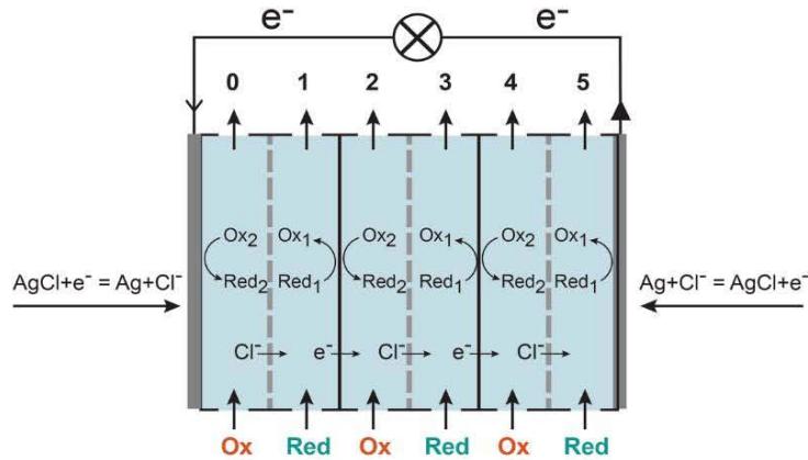
Though described battery has a lot of similarities with traditional batteries, it also has a lot in common with membrane-based systems (Figure 2). Similarly, redox reactions are taking place on two interfaces of chloroplasts, mitochondrial and microsomal membranes in biology, but based on accepted terminology we would not say that our body is filled with electrodes. Of course, there are two coupled redox processes on different surfaces of the foil, but the foil is neither an anode nor a cathode.
The advantage of electrodes is that they may have a very large and developed surface area, thus increasing exchange currents. The disadvantage is that the cells with electrodes are much thicker and heavier. An efficient catalyst immobilized on the foil surface should decrease electrochemical resistance. For example, an exchange current density $i$ is near $10^{-12} \mathrm{~A} / \mathrm{cm}^2$ with $\mathrm{Hg}$ electrodes, and it may be as high as
$$
\begin{array}{l} - k _ {0 1} F \left\{\exp \left[ \alpha_ {r 1} \frac {F}{R T} \left(\psi_ {f 1} - E _ {1} ^ {0}\right) \right] c _ {r 1} - \exp \left[ - \alpha_ {o 1} \frac {F}{R T} \left(\psi_ {f 1} - E _ {1} ^ {0}\right) c _ {o 1} \right. \right\} = \\- k _ {0 2} F \left\{\exp \left[ - \alpha_ {o 2} \frac {F}{R T} \left(\psi_ {f 2} - E _ {2} ^ {0}\right) \right] c _ {o 2} - \exp \left[ \alpha_ {r 2} \frac {F}{R T} \left(\psi_ {f 2} - E _ {2} ^ {0}\right) \right] c _ {r 2} \right\} \tag {3} \\\end{array}
$$
Asymmetry coefficients are mutually related, and $\alpha_{r} + \alpha_{o} = 1$. In equilibrium, for each of the redox pairs total current $i = 0$. Thus, only when each of the redox pairs is acting separately, this gives two familiar Nernst equations for an anode and cathode sides:
$$
\begin{array}{l} \psi_ {f 1} = E _ {1} ^ {0} + \frac {R T}{F} \ln \frac {c _ {o 1}}{c _ {r 1}} \\\psi_ {f 2} = E _ {2} ^ {0} + \frac {R T}{F} \ln \frac {c _ {o 2}}{c _ {r 2}} \tag {4} \\\end{array}
$$
Without equilibrium $\psi_{f1} = \psi_{f2} = \psi_{f}$ because of high conductivity of the foil. Further, in a practically interesting situation with only a reducing agent in the first and only an oxidant in the second solution in the steady-state
$$
-k_{01}F\exp\left[\alpha_{r1}\frac{F}{RT}\left(\psi_{f}-E_{1}^{0}\right)\right]c_{r1}=-k_{02}F\exp\left[-\alpha_{o2}\frac{F}{RT}\left(\psi_{f}-E_{2}^{0}\right)\right]c_{o2}
$$
After simplification it gives
$$
\psi_{f} = \frac{1}{\alpha_{r1} + \alpha_{o2}} \left(\alpha_{r1} E_{1}^{0} + \alpha_{o2} E_{2}^{0} + \frac{RT}{F} \ln \frac{k_{02} c_{o2}}{k_{01} c_{r1}}\right) \tag{6}
$$
This equation is more general than the Nernst equation. It describes the electric potential of a foil as a function of electrochemical properties and concentrations of components of both redox pairs and it is different to a traditional battery description. The foil potential $\psi_{f}$ may be somewhere between two standard potentials, $E_1^0 < \psi_f < E_2^0$. Similarly, corrosion for electrodes dipped into one solution with two redox pairs leads to mixed potentials [13].
Thinking about applications, we can make a few simple estimates. Assume that the transmembrane voltage is $1\mathrm{V}$, and the specific resistance is $1\Omega \mathrm{xcm}^2$. Both are realistic numbers. This gives an electric current of $1\mathrm{A/cm}^2$, and the power per area is $1\mathrm{Watt/cm}^2$. With a stack of foils $10\times 10\mathrm{cm}^2$ each, the power will be enough to light an incandescent 100-Watt bulb in a room. To have 1 Megawatt we need a total $10^{6} \, \text{cm}^2$ of membrane area or $100 \, \text{m}^2$. If the foils are packed in parallel and the foil plus solution thickness is 100 micron ( $10^{-4} \, \text{m}$ ), the volume we need is only $10^{-2} \, \text{m}^3$, i.e., only 10 L. Other obvious applications are power banks to charge $i$ -phones and tablets, battery chargers, car, motorcycles, and especially boat starter (cranking) battery.
Weight is important for many applications. We can assume that $1\mathrm{kg}$ of a solid oxidant has 10 moles of salt, and each molecule accepts 8 electrons, as it is for $\mathrm{NaClO_4}$ reduced into $C I^{-}$. In this case the total charge transferred is $8\times 10^{6}Q / kg$ or 2200 Ah/kg. If the transmembrane voltage is $1\mathrm{V}$, this should give energy near 2200 Wh per kg of solid phase, which is much better than it is for advanced redox fuel cells. Well-known lithium batteries with lithium iron phosphate cathode have energy density of about 160Wh/kg. 12V battery of this type with dimensions $11.42\times 7.87\times 7.87$ inches, weight 26 lbs, and the price near $500 gives 100Ah.
Traditional batteries with N electrochemical cells should have 2N electrodes, connected in series from one cell to another. Presented here redox flow battery will have only N mutually nonconnected foils, which makes a battery assembly simpler, and two current collecting electrodes necessary to convert ionic current to electronic current in the very first and very last cell. It is possible that with time one of the current-collecting electrodes (not necessarily Ag/AgCl) will be practically dissolved. After that it is possible simply to switch positions of reducing and oxidant solutions, thus reversing the electrochemical processes on electrodes.
Batteries and fuel cells are not subject to the Carnot cycle limitations, they may operate with much higher efficiencies than combustion engines and will be comparable to biological energy-converting membranes. The ancillary equipment to operate the device can be a simple pump with channels to supply solutions of reducing and oxidizing agent. The energy necessary for these steps is much less than the chemical energy generated by the cell, which should lead to high energy conversion efficiency. The suggested fuel cell system will be very volume- and energy-efficient. It does not need strong acids and may be easily recharged at home. It will be smaller, lighter, cheaper, and more environmentally benign than existing vanadium-based redox flow batteries [14].
We hope that this paper will also help a more fundamental understanding of the principles and definitions used in the description of electrochemical electrodes, membranes, cells, and batteries [15].
### ACKNOWLEDGMENT
Help of Dr. Trygqvvi Emilsson with experiments and discussions with Professor Yu. M. Vol'fkovich
(Frumkin Institute of Physical Chemistry and Electrochemistry, Moscow) are highly appreciated.
 A
 B
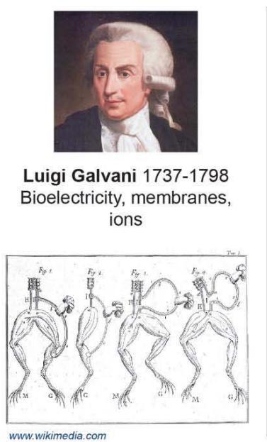 Figure 1: Comparison of electrochemical cells in electrode-based and foil-based redox-flow batteries.
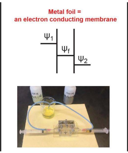
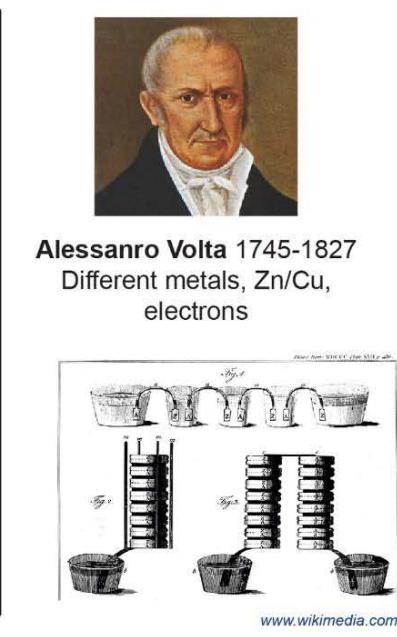 Figure 2: Three different principles of conversion of chemical energy to electrical.
Generating HTML Viewer...
References
15 Cites in Article
B Dibner,Galvani-Volta (1952). A Controversy That Led to the Discovery of Useful Electricity.
C De Santana,W Crampton,C Dillman,R Frederico,M Sabaj,R Covain,J Ready,J Zuanon,R De Oliveira,R Mendes-Júnior,D Bastos,T Teixeira,J Mol,W Ohara,N De Castro,L Peixoto,C Nagamachi,L Sousa,L Montag,F Ribeiro,J Waddell,N Piorsky,R Vari,W Wosiacki (2019). Unexpected species diversity in electric eels with a description of the strongest living bioelectricity generator.
A Volta (2015). The essential Volta. (The Identity of the Electric Fluid with the so-called Galvanic Fluid).
H Tien,A Ottova-Leitmannova (2000). Membrane Biophysics: As Viewed from Experimental Bilayer Lipid Membranes.
N Kocherginsky (2021). Biomimetic membranes without proteins but with aqueous nanochannels and facilitated transport.
N Kocherginsky,M Goldfeld,I Osak (1991). Photo-stimulated coupled transport of electrons and protons across quinone-doped liquid polymer-supported biomimetic membrane.
R Pethrick (1993). Conjugated polymers and related materials. The interconnection of chemical and electronic structure, edited by W. R. Salaneck, I. Lundstöm and B. Rånby. Oxford University Press, Oxford, 1993. pp. xv + 501, price £70.00. ISBN 0‐19‐855729‐9.
N Kocherginsky,Zheng Wang (2007). Polyaniline membrane based potentiometric sensor for ascorbic acid, other redox active species and chloride.
Alexey Serov,Chan Kwak (2010). Direct hydrazine fuel cells: A review.
T Schroeder (2017). An electric-eel-inspired soft power source from stacked hydrogels.
P Kapitza (1928). Electric storage apparatus.
D Mourzagh Electrochemical accumulator with bipolar architecture including a specific structure.
No ethics committee approval was required for this article type.
Data Availability
Not applicable for this article.
How to Cite This Article
N.M. Kocherginsky. 2026. \u201cBiomimetic Redox-Flow Battery without Traditional Electrodes\u201d. Global Journal of Research in Engineering - J: General Engineering GJRE-J Volume 23 (GJRE Volume 23 Issue J2): .
Explore published articles in an immersive Augmented Reality environment. Our platform converts research papers into interactive 3D books, allowing readers to view and interact with content using AR and VR compatible devices.
Your published article is automatically converted into a realistic 3D book. Flip through pages and read research papers in a more engaging and interactive format.
Our website is actively being updated, and changes may occur frequently. Please clear your browser cache if needed. For feedback or error reporting, please email [email protected]
Thank you for connecting with us. We will respond to you shortly.