I. INTRODUCTION
Thermal and non-thermal techniques are most common and popular method for municipal solid waste (MSW) treatment to produce energy. These technologies are widely used to reduce the environmental impacts caused by inadequate waste management [1]. Incineration and all other high temperature treatments are classified as waste thermal treatment. The basic idea of thermal process is to use heat resulting from burning waste to generate energy, while the non-thermal process is to generate energy without direct burning of waste or any burning resource [2].
As a result of continues improvement of thermal technologies, there are about 600 plants using incineration processes has been established recently to produce energy [3].
In addition to incineration, there are two waste thermal techniques which known as advanced thermal treatment (ATT) used in waste industry as gasification, pyrolysis. Pyrolysis can be classified as a process without the use of oxygen. It requires external heat to maintain the desirable temperature, while gasification is considered to be between pyrolysis and combustion with control of oxygen. [5]
Even though several ways are widely used to treat waste in the World, Libyan waste management has not applied any of the basic techniques at any waste treatment level. In this paper, Pfaffenauincineration treatments model has been studied to apply it in El-Marj city. The results show that the rate of waste in the city (kg/capita/day) has been increased from 0.68 in 2006 to 1.08 in 2015. In addition, based on the thermodynamic equation our calculations show that one MW can be generated from one ton MSW. This paper is divided as following, types of thermal of waste treatment, data collections, model, results and conclusions.
II. METHODS OF THERMAL WASTE TREATMENT
| Pyrolysis | Gasification | Combustion | |
| Temperature (°C) | 250 - 700 | 500 – 1600 | 800 – 1450 |
| Pressure (bar) | 1 | 1 – 145 | 1 |
| Atmosphere | Inert/nitrogen | Gasification agent: O2, H2O | Air |
| Stoichiometric ratio | 0 | <1 | >1 |
| Products from the Process | |||
| Gas phase: | H2, CO, hydrocarbons, H2O,N2 | H2,CH4, CO, CO2, H2O, N2 | CO2, H2O, O2, N2 |
| Solid phase: | Ash, coke | Slag, ash | Ash, slag |
| Liquid phase: | Pyrolysis oil and water |
III. EL-MARJ MSWI MUNICIPAL SOLID WASTE INPUT DATA
MSW data are collected from EL-Marj city during the period of (2006 – 2015). In 2001, the percentage of MSW per capita was about 0.915 kg/day, while in 2006 the proportion of the individual production of MSW was 0.98 kg per day. [9] The
The a va er age of waste kg/capita =
In this research, the average number of a family is assumed to be 7.
| Year | Citizens | Waste indicators [kg/capita/ day] | Waste quantity [Kg/year] | Waste quantity [ton/year] | The cumulative amount of waste |
| 2006 | 55340 | 0.68 | 37.7 | 13505 | 13505 |
| 2007 | 62234 | 0.98 | 60.6 | 22228.5 | 35733.5 |
| 2008 | 71674 | 0.99 | 70.95 | 25896.75 | 61630.25 |
| 2009 | 80467 | 1.00 | 80.46 | 29367.9 | 90998.15 |
| 2010 | 89654 | 1.015 | 90.10 | 32886.5 | 123884.65 |
| 2011 | 98675 | 1.028 | 101.43 | 37021.9 | 160906.5 |
| 2012 | 107765 | 1.041 | 112.18 | 40945.7 | 201852.2 |
| 2013 | 116897 | 1.054 | 123.2 | 44969 | 246821.2 |
| 2014 | 125987 | 1.067 | 134.43 | 49067 | 295888.2 |
| 2015 | 135119 | 1.08 | 145.93 | 53264 | 349152.2 |
IV. PHYSICAL MODEL
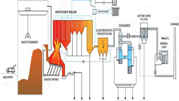
Pfaffenau combustion plant is implemented in this research, data and schematic diagram are shown in the following table 3 and fig.1 respectively.
| Fluidized bed reactor Pfaffenau | |
| Start-up | 1994 |
| Start-up after overhaul | 31.12.2000 |
| Firing technology | Fluidized bed reactor |
| Waste throughput | 26000t |
| Average calorific value of the waste | 5000 - 30000 kJ kg-1 |
| Thermal output | 8 MW |
| Operating hours (test operation) | 7300 |
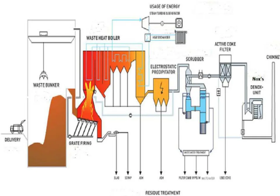
According Pfaffenau model the general construction of the station is consisting of the following units:
1. Waste bunker
2. Firing system: fluidized bed reactor
3. Waste heat boiler
Flue-gas cleaning devices consisting of: Electrostatic precipitator, three-stage wet scrubber,
Catalyst for NOX removal and dioxin destruction
6. Multistage waste water treatment plant
- Steam turbine, generator and heat decoupling system.
This model was constructed in 2000 and it operated since 2001. In the first stage of waste incineration process, the MSW are delivered to waste banker then, moves to the pre-combustion process where metal and glasses are removed. Gas and slug or ashes are produced during the combustion stage. Flue gas is cleaned by using different filters. The clean gas is emitted through chimney in the last stage of the process. Thermal conversation of waste to energy is now very much applied technology for waste management system due to the generation of heat and energy from the waste stream. [6, 8]
V. MATHEMATICAL MODEL AND DATA ANALYSIS
The mathematical model is the model that describes the accounts of the system when changing conditions of operation based on form physical in the, model is as follows: The Fig. 2 shows Diagram of the most essential component of the station.
The calculation of the generated potential energy from MSW incineration is obtained from thermodynamic equations mentioned below and fixed thermodynamic conditions in table 4 [11].
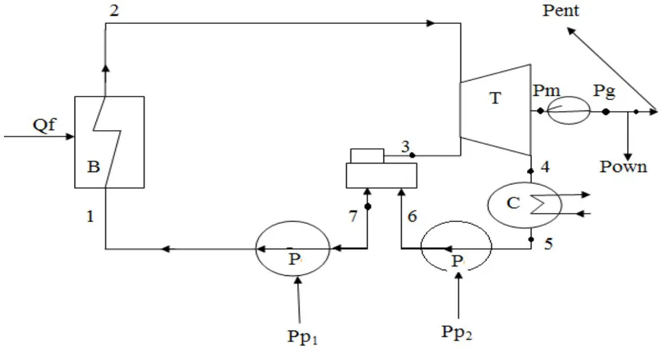
The thermodynamic equation are
mechanical power from turbine ( )
gross electric energy ( )
net electric energy ( ) whine:
m = mass flow rate of steam (kg/s)
electric generator efficiency
= needs of electricity of power plant (6%.Pg)
= enthalpy input to turbine (kJ/kg)
The amount of heat supplied by fuel ( )
The amount of steam supplied by boiler (Qs)
Overall Efficiency of The Plant ( ) needs of electricity of power pump ( )
Thermal efficiency (%)
S.f.C specific fuel consumption ( / kW h)
S.S.C specific steam consumption ( / kW h) By conducting the calculations on the station and at temperatures ranging from 400 to 600 the change in output power ranging from 20 to 40 MW. Our calculations based on the upper equations show that the best efficiency can the plant reached is 28% at a temperature of 600 C° with lowest rate of fuel consumption. These results are show in table 5, table 6, table 7.
| Point | Condition | Given data |
| 1 | Compressed water | P = 95 bar T= 45 |
| 2 | Superheated steam | P = 90 bar,T =400 to 600 |
| 3 | Wet steam expansion from 2 | P = 6 bar, = 97% = 75% |
| 4 | Wet steam expansion from 3 | P = 0.06 bar, X = 0.88 |
| 5 | Saturated liquids | P = 0.06 bar |
| 6 | Compressed water | P = 6.5 bar |
| 7 | Saturated liquids | P = 6 bar |
| 8 | Water | P = 1 bar, T = 20 |
| 9 | Compressed water | P = 2 bar |
| 10 | Compressed water | P = 1.5 bar, T = 30 |
| , MW | , kg/s | s.f.c, kg/kwh | S.S.C | Mcw | ||
| 20 | 3.2 | 27 | 20 | 0.58 | 5.4 | 1878 |
| 25 | 4.05 | 27 | 20 | 0.58 | 5.3 | 2347 |
| 30 | 4.8 | 27 | 20 | 0.58 | 5.3 | 2738 |
| 35 | 5.5 | 27 | 20 | 0.58 | 5.3 | 3207 |
| 40 | 6.2 | 27 | 20 | 0.58 | 5.3 | 3598 |
Table 6: Shows the results of the study at a temperature of 500
| , MW | Mf, kg/s | ,% | s.f.c, kg/kwh | S.S.C Kgs/kwh | Mcw | |
| 20 | 2.6 | 25 | 25 | 0.46 | 3.8 | 1353 |
| 25 | 3.2 | 25 | 25 | 0.46 | 3.8 | 1664 |
| 30 | 3.9 | 25 | 25 | 0.46 | 3.8 | 2026 |
| 35 | 4.3 | 25 | 25 | 0.46 | 3.8 | 2388 |
| 40 | 4.9 | 25 | 25 | 0.46 | 3.8 | 2214 |
Table 7: Shows the results of the study at a temperature of
| s.f.c, | S.S.C | Mcw | ||||
| 20 | 2.3 | 38 | 28 | 0.4 | 3.1 | 1118 |
| 25 | 2.8 | 38 | 28 | 0.4 | 3.1 | 1344 |
| 30 | 3.4 | 38 | 28 | 0.4 | 3.1 | 1666 |
| 35 | 4.1 | 38 | 28 | 0.4 | 3.1 | 1988 |
| 40 | 4.8 | 38 | 28 | 0.4 | 3.1 | 2214 |
VI. RESULTS AND ANALYSIS
Based on the fixed values taken from the table 4 the electrical energy produced from 20-40 MW were calculated during the changes of temperature degrees from 400 to 600 C°. From equation (1) the mechanical energy was calculated ( ) and by using equation (2) we calculated ( ) gross energy and from it we got the total efficiency energy ( ). From the thermal capacity of waste (CV) which amounts from 5000-30000 kJ/kg, where we had assumed it to be (30000), the thermal energy of waste ( ) was calculated from equation (4) and with using table steam on the temperature degrees from 400-600C° the Enthalpy steam ( ) was found and from it the thermal energy of steam (Qs) was calculated. Through the previous equations, the thermal efficiency was calculated ( ) with the reparation in equation (7) and the total efficiency ( ) from equation (6). Also the rate of consumption of fuel and gas (S.f.c), (S.S.c) from equation (8,9) and through it we obtain the results that are provided in the tables (5) (6) (7) that show each study on its own included with the change of temperature degrees from 400,500,600C° respectively.
After holding these accounts on bikes mentioned the heat was taking the temperature of C and C and found that there is an increase in the overall efficiency of the plant with a lack of consumer waste mass.
VII. CONCLUSIONS
In this paper we have calculated the daily amount of solid waste for each person, so it can be used to generate the thermal or electrical energy by burning it in the bed furnace and thus gaining heat with temperature above 850c°. We have applied thermodynamic equations to calculate the daily amount of solid waste for each person, so it can be used to generate the thermal or electrical energy by burning it in the bed furnace and thus gaining heat with temperature above 850c°. We have applied thermodynamic equations to calculate the rate of produced energy from 20Mw to 40Mw with change in temperature from 400c° to 600c° and to achieve results for the rate of fuel consumption, total efficiency and thermal efficiency. From these results it has been shown that the most efficient and least consumed fuel is at temperature of 600c°.