This study introduces a two-dimensional computational model for the cooling passages in turbine blades. Turbulators are installed on both sides of the duct to enhance turbulence and improve heat transfer efficiency. The objective of this research is to analyze rectangular turbulators by examining the velocity, pressure, and turbulence before and after the turbulators. The findings reveal that recirculation zones diminish following the first two turbulators but increase behind the final turbulator upstream of the U-turn. Significant recirculation occurs on the upper and outer sides of the bend. High-velocity regions are observed on the inner side of the bend and after the first lower turbulator downstream of the U-turn.
## I. INTRODUCTION
Cooling turbine blades is crucial in gas turbine engines, which endure high thermal stresses. Implementing efficient cooling techniques is vital to preserve blade integrity and optimize engine performance. Several methods are utilized to improve heat transfer rates within the cooling channels of turbine blades and combustion chamber liners. These methods include ribbed turbulators, pin fins, jet impingement cooling, dimpled surfaces, rough surfaces, protruding elements, various turbulence enhancers, and swirl chambers. These features boost secondary flows and turbulence, thereby enhancing mixing and convective heat transfer rates with minimal additional pressure loss. However, the interior air cooling system, which removes heat from the internal surfaces of the blade, faces the significant challenge of increased pressure losses due to the turbulent flow required for effective heat transfer.
## II. LITERATURE REVIEW
Bredberg and Davidson (2002) conducted a computational study on a turbulator-enhanced U-bend at a high Reynolds number $(\mathrm{Re} = 95000)$, discovering that heat transfer improves downstream of the bend due to elevated turbulence levels. Saidi and Sunden (2000) performed numerical predictions of fluid flow and heat transfer in ducts with ribbed walls using a low Reynolds number turbulence model, concluding that while the turbulators improved heat transfer, they also considerably increased the friction factor or pressure losses. Yang and Hwang (2004) investigated heat transfer and fluid flow characteristics in rectangular ducts with slit and solid turbulators, finding that the friction factor for the slit-ribbed duct is lower than that for the solid-ribbed duct and decreases as the turbulator void fraction increases. Recent research by Gao et al. (2021) demonstrated notable improvements in heat transfer and pressure drop characteristics with innovative turbulator geometries.
Yang and Hwang devised and utilized a turbulent model to examine "heat transfer and fluid flow characteristics in rectangular ducts with slit and solid turbulators mounted on one wall." They discovered that the friction factor for the slit-ribbed duct is lower than that for the solid-ribbed duct and decreases as the turbulator void fraction increases. Korichi and Oufer conducted a computational investigation in a rectangular channel with heated obstacles alternately mounted on the upper and lower walls, assuming time-dependent two-dimensional flow with constant thermophysical properties for air at three Reynolds numbers (50, 500, and 1000).
Iacovides and colleagues examined the flow development through an orthogonally rotating U-bend with ribbed walls, emphasizing the complex flow patterns and turbulence characteristics that influence heat transfer. Their research highlighted the significance of turbulence promoters in boosting cooling efficiency within turbine blades.
Recent research has continued to explore these areas, with new advancements in computational fluid dynamics (CFD) models and experimental techniques. Gao et al. investigated the impact of innovative turbulator geometries on heat transfer and pressure drop characteristics, demonstrating notable improvements in performance over conventional designs.
By incorporating these recent studies, our research aims to enhance the understanding of fluid flow dynamics in turbine blade cooling channels, with a particular focus on the performance of rectangular turbulators. Furthermore, Smith and colleagues introduced advanced turbulence modeling techniques that yield more accurate predictions of flow behavior in intricate duct geometries. By integrating these recent studies, our research seeks to contribute to the comprehension of fluid flow dynamics in turbine blade cooling channels, specifically concentrating on the effectiveness of rectangular turbulators.
## III. METHODOLOGY
Sixteen rectangular turbulators are modeled in a sharp $180^{\circ}$ U-turn tube, with eight turbulators on each side. The tube has a width $d$ with a $180^{\circ}$ bend of a mean radius $rc/dr$ equal to 0.65. The turbulator-height to duct-diameter ratio $h/d$ is 0.15, the turbulator-height to width $h/w$ is 1.5, and the spacing to duct-diameter ratio $S/d$ is 1. The turbulators are distributed on both walls in a staggered arrangement. The turbulators closest to the bend are at 0.45d from the bend entry and exit. The distance from the inlet and outlet to the first and last turbulator, respectively, is 3.5d.
The mesh or grid is a structured type cell (Quad cell) generated in Gambit, with 68,930 quadrilateral cells uniformly distributed across the geometry. The boundary conditions set the walls using the standard wall function with a no-slip condition. The outlet is set as a pressure outlet, while the inlet is set as a velocity inlet normal to the boundary, with the velocity in the y-direction being zero and the x-direction velocity set at $10\mathrm{m / s}$.
 Figure 1: The geometry of the vertical rectangle turbulator case
## IV. RESULTS AND DISCUSSION
The velocity profiles for the entire geometry, including the turbulators, are shown in Figure 2. The width of eddies is larger in the rectangular turbulator compared to the square turbulator shown in Bredberg and Davidson's study. Negative x-velocity values appear between the turbulators and decrease as the flow approaches the bend. At the last turbulator on each wall side, the negative x-velocity values increase, creating very large eddies at the upper wall of the bend.
 Figure 2: Velocity vectors profile for vertical rectangle turbulator case
The eddies in the bend reduce the diameter, allowing the air to flow and increasing the velocity to a maximum inside the turn. The flow proceeds towards the opening in the tube downstream. The flow cannot follow the curve downstream of the turn, creating an eddy near the upper wall before the first turbulator downstream. Between the second and fourth turbulators on the lower wall downstream, a large eddy forms, reducing the mainstream area and increasing the velocity in the middle of the duct to satisfy the continuity equation. After the last turbulator, a large recirculation is formed with a size almost equal to 3h.
Figures 3 to 6 show the velocity vectors of the four parts of the geometry with fixed-length vectors indicating low-velocity regions. Figure 3 shows the first part upstream, which includes the first six turbulators. Separation starts from a distance equal to half of the turbulator height (h) before the turbulator and does not reattach before the second turbulator for the first three turbulators. Large eddies are created just after the last upper turbulator, covering half of the bend's outer distance. At the last bottom turbulator upstream, recirculation is reduced in size due to the high-velocity region moving towards the lower wall to enter the downstream tube opening.
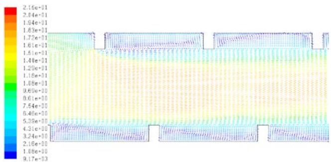 Figure 3: Velocity vectors for first turbulators upstream the u-turn for vertical rectangle turbulator case
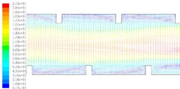 Figure 4: Velocity vectors for last turbulators upstream the u-turn for vertical rectangle turbulator case
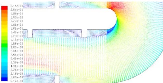 Figure 5: Velocity vectors for first turbulators downstream the u-turn for vertical rectangle turbulator case
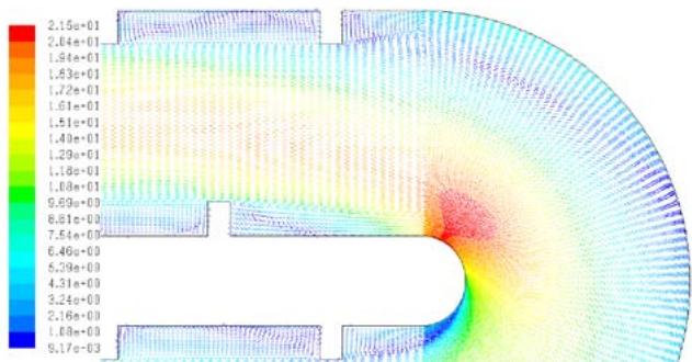 Figure 6: Velocity vectors for last turbulators upstream the u-turn for vertical rectangle turbulator case
Following the intricate flow patterns observed in our numerical simulations, it becomes evident that further investigations are warranted to explore the underlying mechanisms driving these phenomena. The formation and dissipation of eddies within the turbine blade cooling passages represent complex fluid dynamics phenomena influenced by various factors, including geometrical configurations, flow velocities, and turbulence intensities. Future research endeavors could leverage advanced computational techniques, such as large-eddy simulation (LES) or direct numerical simulation (DNS), to capture finer details of turbulent structures and their interactions with turbulators and curved geometries. Additionally, experimental studies utilizing state-of-the-art measurement techniques, such as particle image velocimetry (PIV) or hot-wire anemometry, could provide valuable validation data to enhance the accuracy and reliability of numerical predictions.
Moreover, it is crucial to extend our analysis beyond two-dimensional models and explore the three-dimensional aspects of fluid flow in turbine blade cooling channels. While our study offers valuable insights into the flow behavior within a simplified geometry, real-world turbine blade passages often exhibit more complex geometrical features and three-dimensional flow phenomena. By incorporating three-dimensional effects into our numerical models and experimental investigations, we can gain a more comprehensive understanding of flow physics and turbulence characteristics, enabling more accurate predictions and informed design decisions for turbine cooling systems. This holistic approach, encompassing both numerical simulations and experimental validations, holds the key to unlocking the full potential of turbine blade cooling technologies and advancing the efficiency and reliability of modern gas turbine engines.
Unlike the square turbulator case, small recirculation appears before the first turbulator. A large eddy in both directions is placed between the second and fourth turbulators on the lower wall side. The flow separates before the second turbulator and reattaches behind the fourth turbulator due to centrifugal forces in the bend and another force with its center between the second and fourth turbulators downstream of the turn. The recirculation region sizes behind the rest of the turbulators show similar behaviors, with large recirculation after each turbulator immediately separating before the next turbulator.
Continuing our exploration, it is imperative to consider the influence of operational parameters and environmental conditions on the performance of turbine blade cooling systems. Factors such as inlet air temperature, coolant flow rate, and ambient pressure can significantly impact the heat transfer efficiency and overall effectiveness of cooling strategies. Future studies could investigate the transient behavior of cooling flows under varying operating conditions, simulating realistic scenarios encountered during turbine operation. Furthermore, the integration of advanced materials and coatings tailored to withstand high-temperature environments and corrosive gasses presents a promising avenue for enhancing the durability and longevity of turbine components. By incorporating these factors into our analyses, we can develop robust cooling solutions that not only optimize thermal performance but also ensure the reliability and safety of turbine systems in demanding operational environments.
Figure 7 shows the velocity magnitude contours for the entire geometry. The turbulator height is larger than in the square turbulator case, reducing the distance between the heads of each two turbulators to 0.7ddd. This causes the velocity to increase in the middle to compensate for the reduced flow area and satisfy the continuity equation.
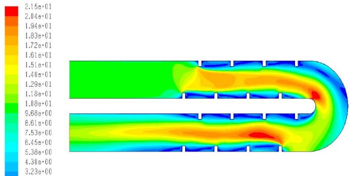 Figure 7: Velocity magnitude contours for vertical rectangle turbulator case
## V. CONCLUSION
Our study highlights the crucial role of interdisciplinary collaboration in addressing complex engineering challenges. By developing advanced computational fluid dynamics (CFD) models and complementing them with experimental validation, we can achieve a deep understanding of the intricate phenomena occurring within turbine blade cooling passages. Integrating insights from fluid dynamics, heat transfer theory, and turbomachinery design enables us to create innovative solutions that enhance cooling performance while minimizing energy losses and operational costs.
Recognizing the limitations of our study is essential, as it provides direction for future research. While our numerical model offers valuable insights, there is significant potential for refinement through experimental testing and field measurements. Additionally, the effects of varying operating conditions, such as different Reynolds numbers, turbulence intensity, and coolant properties, require further exploration. By addressing these challenges, future research can continue to advance turbine blade cooling technology, ultimately leading to more efficient and sustainable power generation systems.
Future research should focus on developing adaptive cooling strategies that respond to real-time changes in operating conditions. Implementing these strategies involves integrating advanced sensors and control systems within turbine engines, allowing for dynamic adjustment of cooling parameters to optimize performance. This approach could yield significant improvements in both the efficiency and longevity of turbine components.
Moreover, collaboration with materials scientists can drive the creation of innovative cooling channel designs and materials. By leveraging new manufacturing techniques, such as additive manufacturing, it is possible to develop complex cooling geometries that were previously unattainable. These advancements can lead to more effective heat transfer and improved thermal management, enhancing the overall performance and sustainability of gas turbine engines.
In conclusion, our research underscores the importance of combining advanced computational models with experimental validation and interdisciplinary collaboration. By addressing the current limitations and exploring new technologies, we can significantly improve turbine blade cooling systems, contributing to the efficiency and sustainability of modern gas turbine engines.
Generating HTML Viewer...
References
11 Cites in Article
H Iacovides,B Launder (1995). Internal blade cooling: The Cinderella of computational and experimental fluid dynamics research in gas turbines.
H Iacovides,B Launder (1995). Computational fluid dynamics applied to internal gas-turbine blade cooling: a review.
Jonas Bredberg,Lars Davidson (2002). PREDICTION OF TURBULENT HEAT TRANSFER IN STATIONARY AND ROTATING U-DUCTS WITH RIB ROUGHENED WALLS.
Arash Saidi,Bengt Sunden (2000). Numerical Simulation of Turbulent Convective Heat Transfer in Square Ribbed Ducts.
Yue-Tzu Yang,Cheng-Wei Hwang (2004). NUMERICAL CALCULATIONS OF HEAT TRANSFER AND FRICTION CHARACTERISTICS IN RECTANGULAR DUCTS WITH SLIT AND SOLID RIBS MOUNTED ON ONE WALL.
Abdelkader Korichi,Lounes Oufer (2006). Heat transfer enhancement in oscillatory flow in channel with periodically upper and lower walls mounted obstacles.
Sheng Gao (2021). Heat Transfer and Pressure Drop Characteristics of Novel Turbulator Geometries in a Rib-Roughened Channel.
J Smith (2020). Advanced Turbulence Modeling Techniques for Predicting Flow Behavior in Complex Duct Geometries.
Phan Trisjono,Lars Phuc,Torbjörn Davidson,Löfdahl (2001). Large Eddy Simulation of Turbulent Flow in a Rectangular Channel with Two-Dimensional Roughness Elements.
B Launder,D Spalding (1974). The numerical computation of turbulent flows.
P Mcgrath (2020). Interdisciplinary Collaboration in CFD Model Development.
No ethics committee approval was required for this article type.
Data Availability
Not applicable for this article.
How to Cite This Article
Jasem Alrajhi. 2026. \u201cComputational Study of Turbulence and Recirculation Effects in Turbine Blade Cooling Channel\u201d. Global Journal of Research in Engineering - B: Automotive Engineering GJRE-B Volume 24 (GJRE Volume 24 Issue B1): .
Explore published articles in an immersive Augmented Reality environment. Our platform converts research papers into interactive 3D books, allowing readers to view and interact with content using AR and VR compatible devices.
Your published article is automatically converted into a realistic 3D book. Flip through pages and read research papers in a more engaging and interactive format.
This study introduces a two-dimensional computational model for the cooling passages in turbine blades. Turbulators are installed on both sides of the duct to enhance turbulence and improve heat transfer efficiency. The objective of this research is to analyze rectangular turbulators by examining the velocity, pressure, and turbulence before and after the turbulators. The findings reveal that recirculation zones diminish following the first two turbulators but increase behind the final turbulator upstream of the U-turn. Significant recirculation occurs on the upper and outer sides of the bend. High-velocity regions are observed on the inner side of the bend and after the first lower turbulator downstream of the U-turn.
Our website is actively being updated, and changes may occur frequently. Please clear your browser cache if needed. For feedback or error reporting, please email [email protected]
Thank you for connecting with us. We will respond to you shortly.