Impulse loading of a sample of limited dimensions (at least two free surfaces) leads to the oscillation of the sample in the standing wave mode as a consequence of wave reflection from the faces and their interaction with each other. Localized strain bands originate and evolve at the standing wave nodes (wave interference zone), where the deformation of the material occurs in the compression-tension mode and the stress in the wave interference zone does not exceed the spall strength of the material. (Excessive stress leads to the formation of spall cracks and sample destruction). As a result of the absence of energy transfer through the nodal points, which is typical of standing waves, the deformation of the sample can last for a long time after passing a shock wave until dissipative processes would bring about oscillatory process damping. Another characteristic feature of standing waves is the formation of new harmonics with their own wavelengths and vibration eigen frequencies with new spall damage occurring at each node.
## I. INTRODUCTION
Localized strain bands on forged platinum blanks were first observed by Tresca in 1879 who explained this phenomenon by the conversion of the mechanical work into heat. The thermomechanical localization model was formed in 1944 [1]. The reason for strain localization is the loss of plastic flow stability because of thermal softening. Since the 1960s, shear bands have begun to be called adiabatic, because the released heat has no time to dissipate under the conditions of large deformations and high velocities [2]. The thermomechanical model of strain localization underwent almost no changes up to the present time. Despite common acknowledgement, the thermomechanical model of strain localization has failed to propose any physical insight into the origin and development of localization, cannot predict sites of localized strain bands (LSBs), cannot explain why the localization appears in very thin bands when the entire sample is subjected to deformation, and provides no idea of the dependence of the critical parameters of the localization onset on the initial structures.
The majority of works on studying LSBs relates to the materials engineering aspect, which accounts for availability of good measuring equipment. The microstructure characterization after dynamic loading is very important for understanding the shear localization mechanism. In spite of a high level of description of changes in the substance that take place after its impulse loading, the factors causing them remain unknown, since the samples retained after explosive loading are studied. The ratio between changes in the sample structure during deformation and after it can be ambiguous. According to authors' opinion [3], the physical interpretation of these phenomena often turns out to be far from reality. One of the reasons for this state is the failure to take into account the compressibility of a solid under impulse loading. The strain localization process accompanies almost all shock and explosive impacts on the material. Pulse processes differ markedly from quasi-static ones, since they lead to a change in the structure and density of the metal, the propagation of compression waves (shock waves) or unloading waves, and the formation of a mass flow of matter, which cannot be ignored. The review on the problem of strain localization in metals is presented and the mechanism of the formation of localized strain bands (LSBs) and mechanisms accompanying the localization of processes leading to changes in the band microstructure are studied in this article. The LSBs are considered as material prefracture. The wave pattern of the process was considered nearly for every experiment and eliminated an ambiguity in the interpretation of experimental data based on the study of the samples retained after explosive loading. The basis of this work is taking into account the compressibility of the material.
a) Why "localized strain bands" rather than "adiabatic shear bands"?
Adiabatic shear bands as a consequence of thermal decompression of the material must have a high temperature. It seems impossible nowadays to experimentally measure the temperature in localization bands and, hence, it is calculated. According to different sources, the calculated temperature is $500^{\circ}\mathrm{C}$ [4], $600^{\circ}\mathrm{C}$ [5], or $800^{\circ}\mathrm{C}$ [6]. The Jones-Cook [6] and Zerilli-Armstrong [7] models most commonly used in temperature calculations contain five fitting parameters. Such models are not suitable for describing impulse processes [8], because they inadequately describe the processes behind the shock wave front and ignore the wave amplitude, density, flow limit change, and plastic properties of materials. Doubts about thermal softening were given [9]. The temperature recorded by an infrared detector is total over the surface area (spot radius $\sim 45$ $\mu \mathrm{m}$ ) and is not characteristic of the band temperature. As shown in [9], an increase in the total temperature before localization is quite insignificant. Taking into account thermal conductivity of the medium adjacent to the hot spot shows that the lifetime of the spot with an initial temperature of $800^{\circ}\mathrm{C}$ is only 1 ns [10]. The work [5] is interesting because the model of a deformed body is not used to calculate the temperature. The irreversible loss of plastic deformation energy under impulse loading is estimated on the account of the geometric interpretation of the conservation laws. In the P-V diagram (pressure-specific volume), the irreversible energy is equal to the surface area between the Rayleigh-Michelson straight line and the Hugoniot curve. The authors suggest that the loss of plastic flow stability and the transition from uniform deformation to that when a "trap" is formed to capture the released energy occur at a certain shock wave pressure. The authors of [5] attributed all the released heat to a thin shear band when obtaining the temperature in the band equal to $600^{\circ}\mathrm{C}$, which is $250^{\circ}\mathrm{C}$ higher than the shock compression temperature. According to the estimates [5], the calculated time of high temperature existence is several nanoseconds after the passage of the shock wave front. It seems doubtful that such a short heating duration could significantly influence the formation of the macrolocalization process.
The solution of the nonstationary one-dimensional nonuniform partial differential heat equation is given in [11]. The shock wave at pressures of 10–20 GPa is weak, the temperature at the wave front, as a rule, does not exceed $350^{\circ}\mathrm{C}$, and the residual heating is $30^{\circ}\mathrm{C}$. Instant heating at the shock wave front was specified to be $350^{\circ}\mathrm{C}$. Localized shear bands were simulated by thin metal plates, on the surfaces of which a residual temperature of $30^{\circ}\mathrm{C}$ was specified. During high-speed deformation, the heat removal of energy was carried out by thermal conductivity.
The internal heating source due to plastic deformation was simulated by the equation:
$$
g(x,t) = 600 \frac{\exp(-\alpha t)}{T_e} \left[ \frac{K^o}{\mu s} \right].
$$
Under competitive conditions, the operation of the internal heating source noticeably reduced the rate of heat removal from LSBs. The titanium alloy had the highest temperature heating compared to other metals. Thus, the maximum temperature of a localization strip with a thickness of $50~\mu \mathrm{m}$ from the initial temperature, which is close to the residual temperature, is $220^{\circ}\mathrm{C}$, while for an aluminum alloy it is only $65^{\circ}\mathrm{C}$, the cooling time of a LSB with a thickness of $10~\mu \mathrm{s}$ under the competitive conditions between thermal conductivity and the operation of an internal heating source does not exceed $1~\mu \mathrm{s}$.
The name of localized strain bands as adiabatic appears outdated and does not reflect their specific features.
## II. SPALLATION MODEL OF STRAIN LOCALIZATION
It was shown for the first time [12, 13] that strain localization is a result of high-velocity tension of the material rather than thermal softening. Under explosive loading conditions, LSBs arise in the interference zone of unloading waves, where tension stresses do not exceed the dynamic strength and the material retains its continuity. Essentially, a localized strain band is an incomplete spall crack. Spalling is a type of dynamic destruction of a material due to the interference or focusing of unloading waves where tension stresses exceed the spallation strength. Spall cracks develop into LSBs when the tension stresses in the interference zone of unloading waves become less than the spall strength of the material.
The spall nature of LSBs formation means that the strain localization depends on the sample geometry and is practically independent of the properties of the material. The geometric factor of arrangement of the free faces, which are sources of unloading waves, is a tool that makes it possible to control the plastic strain localization process and to determine the site of damage appearance in a sample. Under controlled conditions, localized bands of various types were obtained (planar, channel, angular, needle-like, radial, and annular [14]), which made it possible to formulate the conditions for the origin and development of LSBs, i.e., to solve the problems that the thermomechanical localization model failed to solve.
### a) Materials and Methods
The shock load on a sample is traditionally carried out using an explosive charger. To comprehensively compress the sample, the charge surrounded the sample, being placed on its outer surface. The loading was carried out by a sliding detonation wave, which generated a shock wave in the sample. This scheme is widely used to study strain localization [15] during the collapse of cylindrical shells [16].
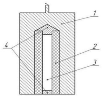
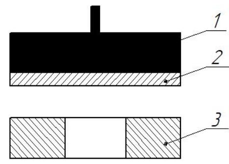 Fig. 3: Glass-shaped sample with a spalled "plate" after an end impact with a plate
Impact loading using a plate accelerated by an overhead explosive charge is a well-known method, which is used, for example, for the determination of the spall strength of a material [17]. The method is convenient for preparing samples (spall "plates") to study the microstructure of LSBs. In this case, the sample has the shape of a beaker with a thick bottom, as shown in fig. 3. The side faces of the beaker hold the emerging spall "plates" in the sample.
A hollow thick-walled metal cylinder (length 70 mm, wall thickness 7 mm, outer diameter 20 mm) was used as the sample under study. The sample-beaker had a length of 20 mm, a bottom thickness of 10 mm, and a thickness of the side faces of 5 mm.
The microstructure study of the samples retained after an explosive impact was carried out using a Neophot-30 optical microscope, a LEO 1450 scanning microscope, and a Zeiss Ultra Plus ultrahigh-resolution electron microscope.
### b) Stability loss of the converging shock wave front
Figure 4 shows the cross-section of a copper hollow cylinder after pulse compression. It can be seen that the relief of the inner surface of the sample has become wavy. The presence of a surface relief of the internal cavity with folds and depressions indicates a stability loss of the shock wave: "bulging" (protrusions) appear at its front. The reason for instability of motion is the narrowing of the flow in cylindrical samples with arising a circumferential compressive stress, which induces disturbances (protrusions) at the shock wave front.
 Fig. 4: Macrostructure of the cross section of the hollow copper cylinder after compression with the detonation wave
The approach of the shock wave to the axis of symmetry is accompanied by an increase in the height of such protrusions.
Apparently, when the size of the protrusions becomes equal to the distance of the front to the axis, the shock wave stops, since the axial space is occupied by its own protrusions, and the cumulative process terminates by the formation of a reflected shock wave.
The exit of the perturbed shock wave onto the free surface is accompanied by the appearance of unloading waves. The sources of unloading waves are free surface areas to which the protrusions of the front approach. Regions of the surface "bulge" under the influence of local unloading waves, and folds of the relief form on the inner surface of the sample. Interference of unloading waves from two nearest folds leads to the formation of spall cracks between the folds, which is clearly seen in Fig. 4. It should be noted that the structure shown in Fig. 4 was formed in two stages. At the first stage, the shock wave, being intensified toward the center, intensively deforms the material, and the grains are crushed and elongated. Damagability occurs at the unloading stage and spreads in the form of a spall crack transforming into the LSBs in the already "milled" material. The deformation of the material by a shock wave and the damage of the material during unloading are two independent processes.
It is noted in [15] that copper and fluoroplastic form a similar system of cracks near the central part of the collapsing sample, which confirms the independence of LSBs of the material used. However, the authors [15] ignored the compressibility of a solid under impulse loading and came to the conclusion that adiabatic shear bands that originated in the already "milled structure," i.e., the structure inside the sample, transform into cracks near the internal cavity. It should be noted that the idea that adiabatic shear bands arise as a result of material deformation is widespread. Ignoring the compressibility of a solid almost invariably leads to an erroneous interpretation of the experiment, since the main processes that determine the impulse behavior of the material are excluded from the consideration.
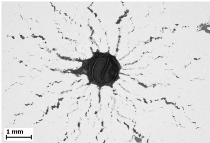 Fig. 5: Microstructure of the central part of a steel cylindrical sample
Figure 5 shows the transformation of spall cracks into localized strain bands in the sample depth, and many of the LSBs are represented by a chain of pores. It should be noted that the exit of a perturbed shock wave onto a free surface always leads to radial spall damage in the form of spall cracks or LSBs between folds of the surface relief.
### c) Standing wave
According to the spallation model, a necessary condition for the formation of LSBs is the presence of at least two free surfaces, which are sources of unloading waves. It is of interest to reveal specific features of LSBs formation when the free surfaces are solid and smooth faces of the sample. A thick-walled hollow cylinder is used as a sample. Dynamic loading was carried out by an impact by the plate on the sample edge. Figure 6 shows that the impact loading of the sample with two free surfaces results in the formation of a system of annular bands of localization strain (circumferential spall damage). The shock wave passing through the sample sets in motion the lateral inner and outer surfaces of the hollow cylinder. The emerging counter propagating waves interact with each other and with the free faces of the sample, which leads to the oscillation of the sample in the standing wave mode [18]. Reflection of waves on the free surface, where the incident wave interacts with its reflected wave, leads to a change in the character of the reflected waves: the unloading wave becomes a compression wave and vice versa. The process of reflection on the free surface is a necessary oscillation mechanism, since it changes the direction of the velocity of the sample faces to the opposite one. The node of a standing wave is the point where the waves collide, and the mass velocity is zero. The deformation of the material in the compression-tension unit is explained by the periodic formation of interference zones of compression waves and unloading waves, which predetermines the origin and development of LSBs at the nodes of a standing wave. The antinodes are the faces themselves where the pressure is zero, and the length of the standing wave is equal to the doubled thickness between the sample faces.
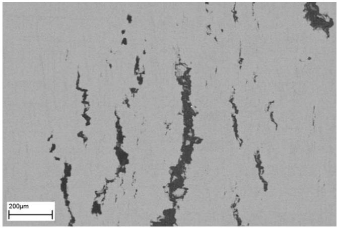 Fig. 6: System of annular localized strain bands in a thick-walled hollow cylinder made of two-phase titanium obtained as a result of the end impact by a plate. Each band is the harmonic node of the standing wave
A specific feature of a standing wave is the formation of energetically closed "compartments" (between the antinode and the node, where the distance is equal to $\frac{1}{4}$ of the wavelength) in which the energy is conserved and not exchanged with neighboring regions resulting in the oscillation continuing after the shock wave attenuation without the action of external forces until dissipative losses would lead to oscillation damping.
Another feature of a standing wave is the formation of new natural oscillations (overtones (harmonics)) as shown in Fig. 6. The main natural vibration with the wavelength equal to the doubled distance between the sources of unloading waves $2\delta$ is formed, as a rule, in the central part of the sample. In a symmetrical standing wave, particles of the medium periodically approach or move away from the node. During the deformation process, additional new LSBs with intrinsic wavelengths are formed around the fundamental harmonic in which the relationship between the thickness of the sample and the overtone wavelength is described by the equation $\delta / 2 = nL_{n} / 4$, where $n = 1,3,5$. The case $n = 1$ refers to the fundamental intrinsic overtone. The LSBs arising at the nodes of standing waves have a coaxial annular shape, which is circumferential spall damage.
A necessary condition for the formation of a standing wave is the presence of at least two free surfaces. The same condition is necessary for LSBs. The result of the experiment proved to be unexpected. It was assumed previously [11-14, 28, 32] that a standing wave is a consequence of the strain localization, but it turned out that LSBs are a consequence of oscillation and should reflect all the features of standing waves. The condition that the stress in the wave interference zone should not exceed the spall strength is preserved. It is also true that it is the tension in the interference zone that determines the damageability of the material. The compression in the interference zones inhibits and slows down the destruction process. The opposite is also true. If LSBs are observed in the experiment, then the sample was in the process of oscillation. The model of strain localization under impulse loading remains to be the spallation one but requires substantial changes.
Strain localization arises at the nodes of standing waves under long-term deformation conditions in the compression-tension mode after passing a shock wave, while the stress in the wave interference zone does not exceed the spall strength. Standing waves in samples of limited size are the result of the interference of counter propagating waves and their interaction with the sample faces.
It should be noted that exceeding the load above the dynamic strength of the material leads to the fragmentation of the sample and formation of fragments in an amount approximately equal to the ratio of the pressure in the shock wave to the value of the spall strength.
### d) Attenuation of standing waves (reverberation)
The question of oscillation damping under shock loads remains unstudied. It is possible to estimate. The damping coefficient $\alpha$ can be estimated using the geometric interpretation of the conservation laws as it was done in [5]. The specific energy converted into heat on the P-V diagram is equal to the surface area bounded by the Rayleigh-Michelson straight line and the load is entropes. The energy attenuation coefficient of a standing wave characterizes the fraction of energy converted into heat to the total energy of a unit mass. According to [5], the specific energy loss is equal to $e = \left(\frac{1}{3}\right)\rho_0c_0^2 b\varepsilon^2$, where $\rho_0$ is the density of the metal, $\varepsilon$ is the degree of deformation equal to $u_{o} / c_{o}$, and $c_{0}$ and $b$ are the adiabatic parameters; $\alpha_{G} = \frac{c^{2}bu_{0}^{3}}{3u_{0}^{2}c_{0}^{3}} = \frac{1}{3} b\varepsilon_{0}$ is the equation determining the energy fraction. When deriving this equation, the authors [5] replaced the is entropy by the adiabatic. For an ideal elastoplastic medium at relatively low pressures, the loss of a portion of the specific energy $e$ depends on the dynamic elastic limit $\sigma_{y}$ and the degree of deformation corresponding to the Hugoniot elastic limit $\sigma_{G}$: $e = \frac{2\sigma_y(\varepsilon - \varepsilon_G)}{3\rho_0}$ [19]. Taking into account that the strain localization arises at stresses slightly lower than the spall strength $\sigma_{s}$, the equation for the fraction of dissipative energy takes the form $\alpha_{S} = \frac{\sigma_{y}(\sigma_{S} - \sigma_{G})}{3\sigma_{S}^{2}}$.
The change in the energy over time, taking into account dissipation, is described by the expression $\frac{dE}{d\tau} = -\alpha E$, which implies $E = E_0 \exp(-\alpha \tau)$, where $\tau$ is the non-dimensional time $\tau = \frac{c_0 t}{\delta} = \frac{t}{T}$, where $c_0$ is the sound speed, and $T = \delta / c_0$ is half the period of the reverberation cycle. The amplitude of a standing wave decays with time according to an exponential law with the coefficient equal to half the attenuation coefficient of the specific internal energy $\alpha / 2$
$$
{ } ^ { A } / _ { A _ { 0 } } = e x p \left[ - { } ^ { \alpha c _ { 0 } t } / _ { 2 \delta } \right] = e x p \left[ - { } ^ { \alpha t } / _ { T _ { 0 } } \right] .
$$
Here $T_{0}$ is the total period of oscillation of the standing wave. The energy attenuation coefficient of the standing wave is equal to the fraction of energy converted into heat divided by the oscillation period $T_{0}$ [20]. The attenuation of a standing wave is characterized by time $t^{\star}$ during which the amplitude of the wave will change $e$ -fold $= 2.718$, $t^{*} = T_{0} / \alpha$. During this time, the standing wave will complete $N$ cycles, $N = t^{*} / T_{0} = 1 / \alpha$. The distance passed by the shock wave and related to the thickness of the sample is $x^{*} / \delta = 2 / \alpha$. The critical value of the mass velocity corresponding to the spall strength is $u_{0} = 0.112 \, \mathrm{mm} / \mu \mathrm{s}$ for a steel sample. In this work, the decay time of the standing wave was calculated by the direct determination of the surface areas on the P-V diagram $(\delta = 7 \, \mathrm{mm}$; sample diameter $20 \, \mathrm{mm}$; speed of sound $c_{0} = 5 \, \mathrm{mm} / \mu \mathrm{s}$; duration of the initial pulse $\Delta = 0.6 \, \mu \mathrm{s}$; pressure of the incoming shock wave $4.2 \, \mathrm{GPa}$; damping coefficient of the specific internal energy calculated from the P-V diagram $\alpha = 0.019$, $T_{0} = 2.8 \, \mu \mathrm{s}$, $t^{*} = 147.4 \, \mu \mathrm{s}$, $x^{*} = 737 \, \mathrm{mm}$, $N = 53$, $t^{*} / \Delta = 245$. For comparison, the dissipative energy fraction in the specific energy is $\alpha_{\mathrm{G}} = 0.0108$ [5], and $\alpha_{\mathrm{s}} = 0.086$ [20], and these fractions may differ by 5-10 times. Thus, after the passage of the shock wave, the sample maintains the oscillatory mode for almost 150 $\mu \mathrm{s}$ more, which is almost 250 times longer than the duration of the initial impulse load.
## III. SPHERICAL IMPACTOR
This is another example of how ignoring the compressibility of solids makes difficult the solution of important practical problems. Spherical shock waves arising by the collapse of cavitation bubbles lead to hardening of the surface layer due to their multiple formation. However, experiments [21] showed the formation of needle-like aggregates in the surface layers at the initial stage of cavitation erosion. The model of erosive wear of a surface under the influence of a flow of spherical particles cannot explain the occurrence of needle-like damageability. Another model that explains damageability by the action of cumulative jets that arise during the asymmetrical collapse of a cavitation bubble cannot explain a sufficiently thick layer of hardened material. The consideration of solid body compressibility appeared as the formation of shock waves during impulse loading shows that it is the spherical impactor that "stings" the obstacle to form a needle-like spall crack.
Figure 7 shows the scheme of interaction a spherical impactor with an obstacle. The equation of motion of the spherical shock wave front and the displacement velocity of the contact surface boundary are presented as follows:
$$
x ^ {2} + (y - 1) ^ {2} = \tau^ {2} \mathtt {H} \frac {d x}{d \tau} = \frac {\tau}{\sqrt {\tau^ {2 - 1}}}, \qquad \tau = \frac {c _ {0 1 t}}{R _ {0}} \geq 1
$$
Here $\tau$ is the nondimensional time, $R_0$ is the initial radius of the sphere at the moment of contact with the surface of the solid, $c_{01}$ is the speed of sound in a liquid medium. At the impact moment $\tau_0 = 1$, the speed of the contact boundary is equal to infinity and quickly decays with the removal from the axis of symmetry.
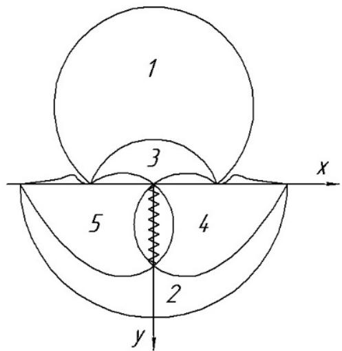 Fig. 7: Scheme of formation of needle-like spall damage. 1, spherical impactor; 2, shock wave in the obstacle; 3, reflected shock wave; 4, unloading wave appearing when a shock wave reaches the surface; and 5, axial focusing area of unloading wave.
The shock wave in the obstacle is "tied" to the contact boundary as long as its speed exceeds the speed of sound in the obstacle $c_{02}$. When the speed of the boundary becomes lower $\frac{dx}{d\tau} \leq \frac{c_{02}}{c_{01}}$, the shock wave overtakes the contact boundary and reaches the surface resulting in the formation of a fold in front of the contact point. Focusing of the resulting unloading wave leads to the formation of a needle-like spall crack oriented along the axis of symmetry [22]. The central undisturbed region of the contact surface is limited by the radius of the first fold formation, which is approximately $0.3R_0$.
Currently, this type of damage has not been studied at all. Needle-like damage accompanies impacts of samples of limited size (fragments) if the thickness of the sample exceeds its radius. In this case, the focusing of the lateral unloading waves manages to outstrip the arrival of the end unloading wave onto the contact surface.
For a normal impact of metallic balls on a metal barrier and high impact speeds, new features of the damageability of the solid surface clearly appear. It is well known from experiments on erosive wear that impact loads by spherical particles induce a wavy surface relief around the undisturbed central spot in plastic materials and circumferential cracks in brittle ones [23]. Changes in the surface layer of a titanium alloy caused by a metallic ball impact were studied [24]. The central contact area remained smooth undisturbed with ring folds formed around it that were called steps in the work. As shown by the longitudinal microsections of the samples, adiabatic shear bands begin from the steps and penetrate deep into the sample and their thickness is several microns. A large shear band (several tens of microns thick) is located under the undisturbed surface and bends round the region of thin LSBs. The authors base their explanation of their experiments on the traditional thermomechanical localization mechanism, according to which the steps are the result of surface heating due to high temperature in shear bands.
However, the consideration of the wave pattern of shock loading of the surface of a solid by the impact of a metallic ball shows anything different. Thin annular LSBs appear under surface regions where the speed of the contact boundary becomes lower than the speed of sound, and the shock wave overtakes the contact point resulting in "bulging" of the surface region. The ball runs over the steps and presses them, which leads to the formation of LSBs. The shock wave that accompanies each blow on the step advances the contact boundary to form new relief protrusions. The authors failed to notice a needle-like crack along the axis of symmetry. As for the thick band of localized shear, this is classical edge spall damage.
It is of interest what will change if before hitting with a metallic ball, the surface of the metal sample would be sprinkled with a small amount of a radioactive powder?
### a) Acceleration of mass transfer under dynamic loads
These experiments were performed in [25]. Using the radioactive tracer technique, the authors showed that radioactive atoms penetrate to depths of hundreds of microns and even up to millimeter. The diffusion coefficients of many metals turned out to be higher than those for metals in the liquid state. As compared to solids, the diffusion coefficient were 6-7 orders of magnitude higher. The diffusion mobility under impulse loads in a dense fcc lattice turned out to be higher than in a loose bcc lattice, and the increase in the coefficient increased with decreasing temperature, while the ordinary mass transfer is characterized by an inverse relationship.
In 1981, the discussion on the problem of anomalous mass transfer moved to the pages of the
Russian journal "Physics and Chemistry of Materials Processing. "The opponent [26] emphasized that the limiting value for the diffusion coefficient in a solid can only be the coefficient in a liquid, while no claims were made against the experiment, and besides, the experiment can always be repeated. Referring to work [26] as the fact proving the inconsistency of anomalous diffusion, in [27] the problem of anomalous mass transfer was closed as non-existent. Nevertheless, information about the acceleration of mass transfer during pulsed processes continued to appear occasionally [28].
In the localized strain bands of a copper sample obtained on a Hopkinson installation, recrystallized grains were found in the form of ultrathin equiaxed particles with a size of $0.05 - 0.5\mu \mathrm{m}$ and having a low dislocation density [29]. The recrystallization time turned out to be five to seven orders of magnitude lower than that required under ordinary conditions. Smaller recrystallized grains about $0.01 - 0.05\mu \mathrm{m}$ in size were observed in steels. Classical mechanisms of recrystallization, migration of high-angle boundaries and merging of subgrains, are unable to explain the grain size in shear bands, since the traditional process of recrystallization is significantly slower than deformation [30].
The unresolved problem of increased mass transfer of particles, which is typical specifically of pulsed processes, is a consequence of insufficient knowledge about the peculiarities of the behavior of metals in the process of strain localization.
## IV. PROCESSES ACCOMPANYING PLASTIC STRAIN LOCALIZATION
### a) Oxidation of fragments in LSBs
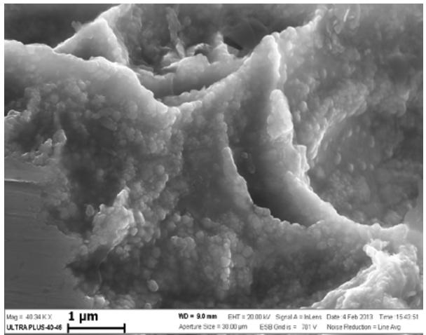
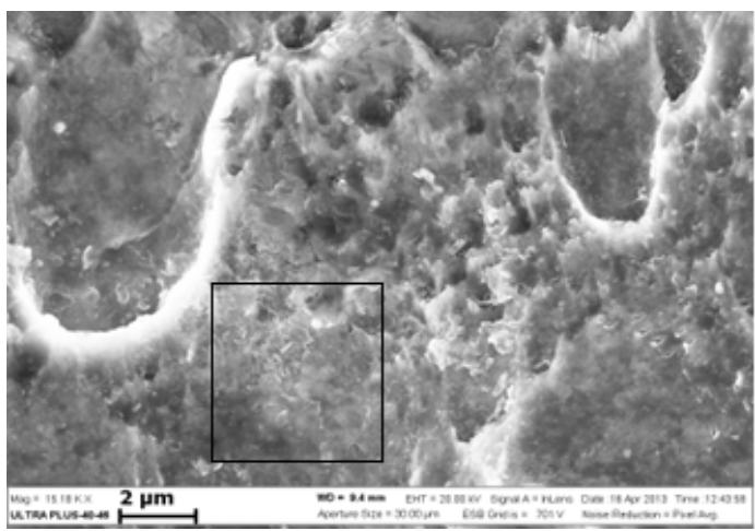
One of the most interesting effects of impulse load on a solid is a change in the structure of the material, phase transitions, and chemical reactions. Figure 8 a and b shows photographs of the microstructure of the LSBs of copper and steel samples. The crushed metal fragments after sample loading are covered with ultrathin lump-shaped particles, whose size does not exceed $100\mathrm{nm}$. The particles turned out to be oxide nuclei. Previously, the formation of the finely dispersed granular coating with smooth spherical surfaces was discovered in the structure of shear bands formed by pores in the copper sample [31]. The authors [31] noted that the presence of copper oxides is accompanied by a significant increase in temperature due to the exothermic oxidation reaction during shear strain. The same authors suggested that during high-velocity deformation oxygen dissolved in the metal during its industrial production migrates from the matrix metal to the sites where plastic deformation is localized.
 Panel label: a.
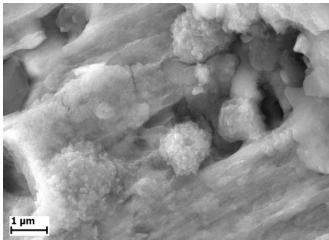
b Fig. 8: Formation of oxide nuclei on fragments inside the spall crack of the copper sample (a) and on the "spall plate" fragments of the steel sample (b).
The migration of oxygen atoms turned out to be a general phenomenon: ultrathin oxide nuclei were observed in the titanium and aluminum samples [32].
### b) Dissolution of intermetallic compounds in localized strain bands
Particles imply interstitial atoms, substitution atoms, impurity elements, and ultrafine particles of the alloying (strengthening) phase. The behavior of intermetallic compounds during strain localization was studied on the dispersion-strengthened aluminum alloy. The phase composition of duralumins containing copper, magnesium, and manganese has been studied fairly well. The aluminum alloy is homogeneous at high temperatures, because the phases containing base metals are soluble. However, duralumins are
contaminated with impurities of iron and silicon, and the composition of the alloy becomes multicomponent, since they contain complex compounds. Figure 9 shows an alloying phase particle in the aluminum alloy. The complex structure of intermetallic particles is determined by a specificity of the heat treatment of the material. The heating temperature for hardening is selected from the condition of maximum dissolution of the strengthening phases: at these temperatures, iron-based intermetallic compounds remain in the solid state, and during cooling they become centers of crystallization of soluble intermetallic compounds, which form a rim with an enhanced copper content. Solid solutions in all hardened duralumins are highly oversaturated with copper, so the rim acquires a bright color due to the fact that the higher the density of the metal, the brighter the image in the rays of reflected electrons. Figure 9 shows that almost all initial particles contain a light iron core surrounded by a bright copper rim.
Figure 10 shows the LSBs microstructure near the region of spall crack transition into the localized strain band. In this case, the high-velocity tension stress is close to the dynamic strength of the material, and this is the maximum possible tensile value at which the continuity of the material is maintained. The microstructure of LSBs consists of a highly deformed material with a large number of micropores, whose size varies from 100 to $400\mu \mathrm{m}$. This pattern is typical of all materials studied (titanium, steel).
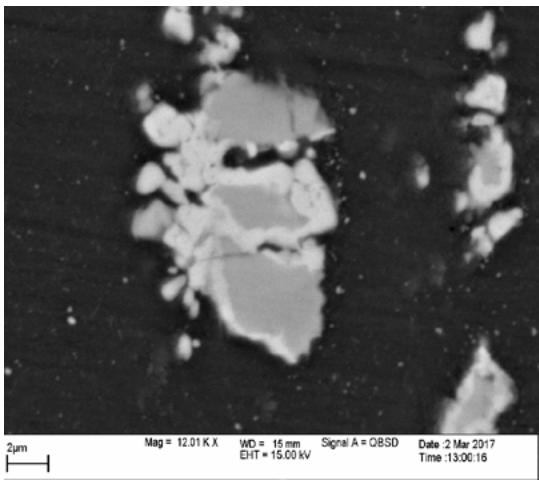
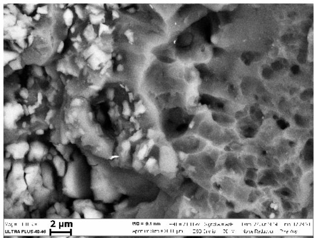 Fig. 9: Initial microstructure of alloying phase particles in the aluminum alloy.
The phase composition of intermetallic compounds in the LSBs underwent changes. The alloying phase particles retain the rim, but its color becomes light, i.e., close to the color of the base alloy. The iron-containing core becomes brighter than the rim indicating that the copper rim has dissolved. Small soluble intermetallic compounds $0.5 - 2\mu \mathrm{m}$ in size, which in the original alloy had the shape of irregular polygons, acquired rounded outlines. The number of particles in the LSBs with a size less than $500\mathrm{nm}$ has increased noticeably compared to the undisturbed material, which indicates the partial dissolution of intermetallic compounds in the LSBs.
### c) Migration of particles to places of spall damage (self-healing effect)
Alloying additives in the dispersion-strengthened aluminum alloy under consideration were arranged in a row in the form of colonies formed during technological rolling. The distance between the colonies of intermetallic compounds varied within $15 - 40\mu \mathrm{m}$, and the individual particle size of the strengthening phase was $0.5 - 2\mu \mathrm{m}$. Figure 11 shows LSBs in the aluminum alloy with particles of intermetallic compounds accumulated at the boundaries. Particle segregation indicates the migration of alloying phase particles from the adjacent matrix region to the spall damage sites. The thickness of the layer, where intermetallic compounds are practically absent and from where they migrate to damaged areas, is $5 - 10\mu \mathrm{m}$ sometimes reaching $20\mu \mathrm{m}$ [32].
Figure 12 shows the microstructure of the LSBs in the two-phase titanium alloy. The initial $(\alpha + \beta)$ structure of the titanium alloy is plate-like. Inside the $\beta$ -phase, colonies are formed from parallel plates of the $\alpha$ -phase (thickness $0.2 - 0.7\mu m$, length $5 - 8\mu m$ ) similar in appearance to pearlite colonies in steel. The average distance between the colonies is about $2\mu m$. Darker areas near the LSBs depleted of $\alpha$ -phase particles do not exceed $3 - 5\mu m$ and are not localized along the entire length of the LSBs.
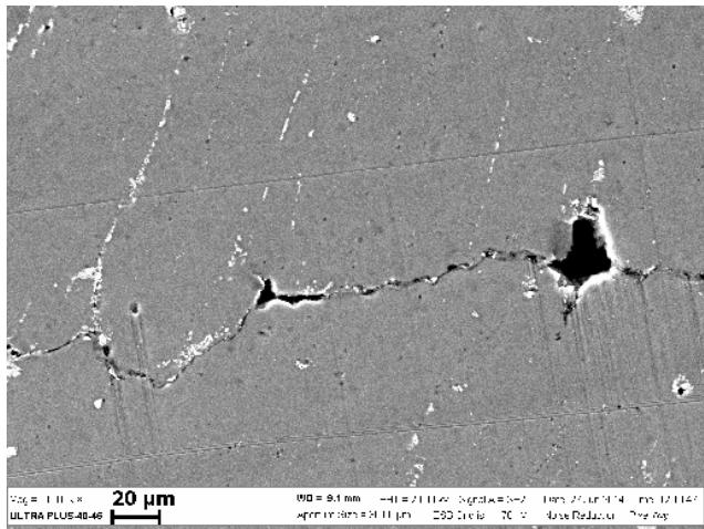
Fig. 10: Microstructure LSBs of duralumin in the zone of transition of the spall crack into the strain localization band.
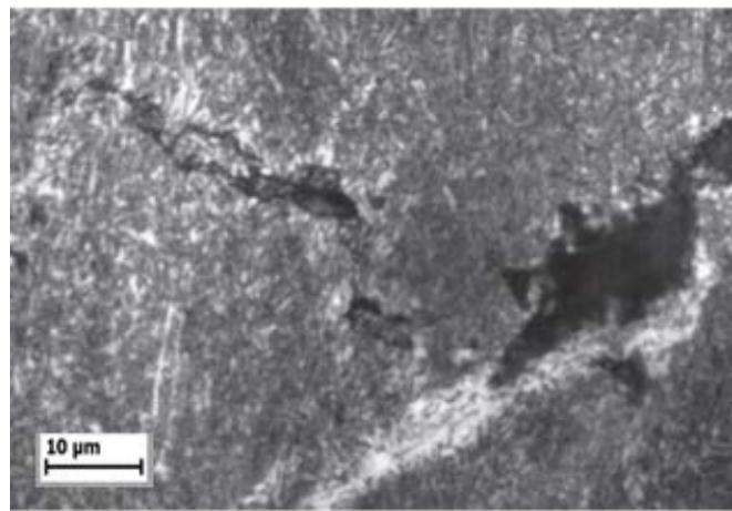 Fig. 11: Segregation of intermetallic compounds on the banks of the localized deformation band in the dispersion-strengthened aluminum alloy Fig. 12: Segregation of
$\alpha$ -phase particles of the two-phase titanium alloy at spall damage sites in the spall "plate" When compared to the aluminum alloy and steel, the area in the two-phase titanium alloy from which ultrafine $\alpha$ -phase particles migrated to the growing discontinuity sites proved to be no more than 5 $\mu$ m. The presence of a significant amount of the $\alpha$ -phase in the LSBs suggests that there may be an additional decay of the $\beta$ -phase during sample deformation in the standing wave. The phase composition redistribution occurs as a result of the segregation of the $\alpha$ -phase in the wave interference zone (LSBs).
### d) Globulation of cementite and mass transfer of carbon during localization
Figure 13 shows a section of the localization band in the area of the contact of cementite plates (length $2 - 3\mu \mathrm{m}$ ) and ferrite ( $50\mu \mathrm{m}$ ). During the formation of LSBs in the standing wave, the metal undergoes fragmentation: cementite plates are crushed. However, some fragments retain clear outlines, and their size is $0.2 - 0.5\mu \mathrm{m}$ [33], as seen in Fig. 13 b. According to [34], the size of the fragments can decrease to a minimum limit of $0.20 - 0.25\mu \mathrm{m}$ as the deformation increases. The blurring of the edges of the cementite plates observed near the ferrite stripes indicates the decomposition of cementite, the size of which is close to the limiting value. It is known that there is a strong interaction between carbon and dislocations. The disintegration of particles during their interaction with dislocations occurs when the binding energy of atoms inside the particles is less than the binding energy of these particles with dislocations. The experimentally observed decomposition of cementite in highly deformed steel reaches $30 - 40\%$ [35]. The numerous dark and gray areas in Fig. 13 represent structureless ferrite. Noteworthy is the presence of a spherical bright particle in Fig. 13 b, which was formed at the blurred boundary of cementite and ferrite. The many small spherical particles of cementite scattered throughout Fig. 13 a, b indicate that two differently directed processes occur in the LSBs: the decomposition of cementite and its reformation. Previously, globular cementite in LSBs was discovered in experiments on dynamic torsion on a Hopkinson installation at a pressure of $0.1 - 0.3\mathrm{GPa}$ and the exposure time up to $100~\mu \mathrm{s}$ [4]. Thin globular cementite with a size of $0.03 - 0.06\mu \mathrm{m}$ was released along the boundary with ferrite.
 Panel label: a.
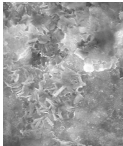
b Fig. 13: Microstructure of steel 3 in the localized strain band. The impactor plate was accelerated by the charge of 6ZhV ammonite (a), area with crushed cementite plates (b).
An increase in the load amplitude above 15 GPa changes the microstructure in the LSBs of the steel sample: almost all pearlite transforms into the globular form, which is clearly seen in Fig. 14. In this case, cementite globules can reach a size of $2 - 3\mu \mathrm{m}$. It is characteristic that the material exists in the porous state near the internal boundary of the LSBs. Microspectral analysis showed the presence of a high carbon content, while in the spherical globule of cementite itself the carbon content corresponds to the formula of the metastable phase $\mathsf{Fe}_{\mathsf{x}}\mathsf{C}$, where $x < 3$.
Energy dispersive analysis of the steel sample to carbon revealed a layer near the LSBs $20 - 40\mu \mathrm{m}$ thick depleted of carbon and a very thin layer directly adjacent to the LSB enriched in carbon. The high carbon content in LSBs was noted in [36]. Microhardness measurements [4] made it possible to identify areas with reduced microhardness $50\mu \mathrm{m}$ thick at both sides of the localization band, while the band itself exhibited increased microhardness.
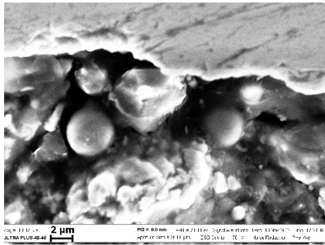 Fig. 14: Microstructure of steel 3 in the region of transition of the spall crack into the localized strain band; the impactor plate was accelerated by a charge of cast TNT.
Microhardness in steels depends on the carbon content and varies almost linearly decreasing by approximately 80 units for every $0.15\%$ (by weight) decrease in the carbon content [37]. The presence of a depleted layer indicates mass transfer of carbon from the adjacent zone of the matrix material to the damage area. The supply of carbon atoms from the matrix to the LSB zone increases the carbon content in the localization band itself, which explains the transition of all pearlite to cementite.
The migration of alloying elements and dissolution of interstitial and substitution phases are well-known for quasi-static cold deformation [38, 39]. The activation of low-temperature dissolution of intermetallic compounds is achieved due to the generation of a large number of point and linear defects and increased diffusion mobility in metal matrices, which is an essential factor in the mechanism of solid-phase reactions. The authors of [38, 39] note that the active development of the mass transfer coincides with the formation of non-crystallographic shear regions with a high local deformation and an intense generation of crystal lattice defects in localization bands. The distance over which atoms can drift was shown to be estimated as $2 - 30\mathrm{nm}$. At the same time, in explosive experiments, mass transfer was carried out over distances exceeding quasi-static distances by several orders of magnitude. Carbon migrates over distances of up to $50~{\mu\mathrm{m}}$ and the process of cementite globulization under normal conditions requires many hours of exposure at high temperatures, which is seven to eight orders of magnitude higher than under impulse loads.
e) On the question of the driving force of a particle flow to the spall damage zone
The thermal pressure in a solid under normal conditions is determined by heating from 0 to $300\mathrm{K}$ and is $P_{T} = \gamma c_{V}\frac{\Delta T}{V_{0}}$, being 1.9 GPa for iron, which is compensated by the elastic pressure of the same value, here $\gamma$ is the Gruneisen coefficient, $c_{v}$ is the heat capacity, and $\Delta T$ is the heating temperature. In LSBs, the maximum permissible stretch, which increases the metal volume, is close to the spall strength of the material. The increase in the volume is determined by the law of conservation of mass and is $\Delta V / V_0 = u_s / D$, where $D$ is the shock wave propagation speed. For a steel sample, the critical mass velocity is $u_{s} = 112~\mathrm{m / s}$. An increase in the volume by $2.3\%$ corresponds to an increase in the elastic pressure $\Delta P_x = \frac{1}{\chi_0}\frac{\Delta V}{V}$, which is equal to 3.8 GPa, here $\chi_0$ is the isothermal compressibility. This is the driving force with which the material will strive to bring the atoms to an equilibrium state and to heal the growing discontinuity setting in motion the flow of "building" material directed toward spall damage.
During high-velocity compression-tension deformation, the equilibrium system is disturbed, and the pressure, temperature, phase composition, and concentration of alloying particles periodically change. The changes occurring in the material enhance the processes of material fracture resistance, and the material strives to heal the growing damage. Under dynamic loading, the response of the material to external influences, Le Chatelier's principle, appears as a self-healing effect, which is aimed at compensating for changes occurring in the system.
Thus, analysis of our and literature data makes it possible to explain the experimentally detected "anomalous" behavior of diffusion [25]. The self-healing effect, as a reaction of the material to impulse loading with the formation of LSBs, used a "suitable building" material in the form of a radioactive metal powder.
## V. CONCLUSION
Summarizing the results of the research, the following should be noted:
1. Under dynamic loading, no new deformation mechanisms were discovered that differed from quasi-static ones and were inherent only in impulse loading.
2. Impulse loading of a sample of limited sizes, which has at least two free faces, is accompanied by oscillation in the standing wave mode as a result of the interaction of counter propagating waves with each other and their reflection on the faces of the sample.
3. Under a dynamic load exceeding the spall strength, the sample is crushed, and the number of fragments is approximately equal to the ratio of the shock wave pressure to the spall strength of the material (according to [40]).
4. Under dynamic loading that is lower than the spall strength, the reaction of the material appears as the formation of localized strain bands at the nodes of the standing wave preserving the continuity of the material.
5. The formation of standing wave harmonics (LSBs) in the interference zones of counter propagating waves (standing wave nodes) indicates the spallation nature of localization bands, where the leading role of the process belongs to the geometry of the sample, the faces of which are sources of unloading waves. Therefore, numerous unsuccessful attempts to relate the localization process to the physicochemical characteristics of the material are understandable.
6. Localized strain bands are formed under conditions of prolonged deformation of the material in the compression-tension mode.
7. The duration of the oscillatory process of the sample after passing the shock wave is determined by the peculiarity of the standing wave to retain energy at one-fourth of the wavelength rather than to exchange energy with neighboring areas. The time of oscillation of the sample after the passage of the shock wave is several orders of magnitude higher than the initial load pulse and is limited only by dissipative processes leading to sample oscillation damping.
8. Strain localization is accompanied by a change in the phase composition inside the deformation bands. The development of physicochemical processes, such as fragmentation, dissolution of particles of the strengthening phase, globulization of pearlite, formation of spheroidal cementite in steels,
- and oxidation of fragments, depends on the intensity and duration of sample oscillation.
9. The protective reaction of the material that accompanies the plastic strain localization as a process that induces damage appears as the formation of mass transfer of dispersed particles of the alloying phase, interstitial elements (O, C), and impurities from the matrix material to the zone of localized strain band formation.
10. The mass transfer of particles under pulsed loads is called the self-healing effect, as it has not previously been described in the literature. Mass transfer has a noticeable effect on the microstructure inside the localization bands supplying additional material, which leads to its restructuring.
11. The distances passed by particles during migration under impulse loading are several orders of magnitude higher than those under quasi-static loads.
Generating HTML Viewer...
References
41 Cites in Article
C Zener,J Holomon (1944). Effect of Strain Rate Upon Plastic Flow of Steel.
T Wright,,P Perzyna, (2002). Physics and Mathematics of Adiabatic Shear Bands.
P Decarli,M Meyers (1980). In the book: Shock waves and high-strain-rate phenomena in metals.
Byoungchul Hwang,Sunghak Lee,Yong Kim,Nack Kim,Dong Shin (2006). Microstructural development of adiabatic shear bands in ultra-fine-grained low-carbon steels fabricated by equal channel angular pressing.
D Grady,J Asay (1982). Calculation of thermal trapping in shock deformation of aluminum.
Wang Xue-Bin (2004). Calculation of temperature distribution in adiabatic shear band based on gradient-dependent plasticity.
J Lins,H Sandim,H-J Kestenbach,D Raabe,K Vecchio (2007). A microstructural investigation of adiabatic shear bands in an interstitial free steel.
N Chend,L Fanc,G Xies,W Huj,X Wus,H Wang,Tah,Y Yuy (2007). Study on constitutive relation and models for oxygen-free high -conductivity cooper under planer shock tests.
D Rittel,P Landau,A Venkert (2008). Dynamic Recrystallization as a Potential Cause for Adiabatic Shear Failure.
D Rittel,S Osovski (2010). Dynamic failure by adiabatic shear banding.
S Buravova,I Gordopolova,E Petrov,M Alymov (2020). Features of ultrasonic vibrations during localization of deformation.
S Buravova,Yu. Gordopolov (2007). Nature of the adiabatic-shear strip formation.
A Belikova,S Buravova,Yu. Gordopolov (2013). Strain localization and its connection with the deformed state of the material.
A Belikova,S Buravova,E Petrov (2013). Localization of deformation under dynamic loads.
V Nesterenko,M Bondar' (1994). Localization of deformation in collapse of a thick walled cylinder.
V Zeldovich,N Frolova,Yu,F Kheifets,Others (2019). Deformation phenomena during the convergence of metal cylindrical shells.
G Kanel,V Fortov,S Razorenov (2004). Shock-Wave Phenomena and the Properties of Condensed Matter.
G Gorelik (1959). Waves in Optics.
G Stepanov (1979). Elastic-plastic deformation of materials under the influence of impulse loads.
S Buravova,E Petrov (2020). Microstructure of metal in spallation plates.
C Preece Cavitation erosion.
S Buravova,Gordopolov Yu (2011). Cavitation Erosion as Kind of Dynamic Damage.
S Timothy,I Hutchings (1985). The structure of adiabatic shear bands in a titanium alloy.
L Larikov,V Brick,V Mazanko,V Falchenko (1975). Intensification of Chemical-Thermal Treatment of Titanium and Its Alloys.
P (2003). This Month's Highlights.
L Krasulinyu,About (1981). anomalous" diffusion in materials under pulsed loading.
E Avvakumov (1986). Mechanical methods for activating chemical processes.
S Buravova,E Petrov (2018). Acceleration of Mass Transfer under Dynamic Loading.
Rus (2018). Kort sagt.
J Hines,K Vecchio (1997). Recrystallization kinetics within adiabatic shear bands.
M Meyers,Y Xu,Q Xue (2003). Microstructuralevolution in adiabatic shear localization in stainless.
Tang Nai-Yong,P Niessen,R Pack (1991). An investigation of shock-induced damage in oxygenfree high conductivity copper.
S Buravova (2017). Self-healing effect of spallation damageability.
S Buravova,E Petrov,M Alymov (2016). Chemical transformations in the zone of spall damageability.
V Rybin (1986). Large plastic deformations and destruction of metals.
A Kulemin (1978). Chapter 4 Diffusion in metals.
C Wittman,M Meyers,H-R Pak (1990). Observation of an adiabatic shear band in AISI 4340 steel by high-voltage transmission electron microscopy.
H Rogers,C Shastry (1981). Material Factors in Adiabatic Shearing in Steels.
A Kuznetsov,V Sagaradze (2002). Dissolution of intermetallic phases in Fe-Ni-Ti alloys with fcc lattice.
V Shabashov (2008). Nonequilibrium diffusion transformations and nanostructuring under intense cold deformation.
J Rinehart,J Pearson (1954). Behavior of Metals under Impulsive Loads.
No ethics committee approval was required for this article type.
Data Availability
Not applicable for this article.
How to Cite This Article
S.N. Buravova. 2026. \u201cDamageability of Metals under Impulse Loading\u201d. Global Journal of Science Frontier Research - A: Physics & Space Science GJSFR-A Volume 23 (GJSFR Volume 23 Issue A11): .
Explore published articles in an immersive Augmented Reality environment. Our platform converts research papers into interactive 3D books, allowing readers to view and interact with content using AR and VR compatible devices.
Your published article is automatically converted into a realistic 3D book. Flip through pages and read research papers in a more engaging and interactive format.
Impulse loading of a sample of limited dimensions (at least two free surfaces) leads to the oscillation of the sample in the standing wave mode as a consequence of wave reflection from the faces and their interaction with each other. Localized strain bands originate and evolve at the standing wave nodes (wave interference zone), where the deformation of the material occurs in the compression-tension mode and the stress in the wave interference zone does not exceed the spall strength of the material. (Excessive stress leads to the formation of spall cracks and sample destruction). As a result of the absence of energy transfer through the nodal points, which is typical of standing waves, the deformation of the sample can last for a long time after passing a shock wave until dissipative processes would bring about oscillatory process damping. Another characteristic feature of standing waves is the formation of new harmonics with their own wavelengths and vibration eigen frequencies with new spall damage occurring at each node.
Our website is actively being updated, and changes may occur frequently. Please clear your browser cache if needed. For feedback or error reporting, please email [email protected]
Thank you for connecting with us. We will respond to you shortly.