
I. INTRODUCTION
Sandwich construction has been used in many earlier circumstances, one of the earliest notable application of sandwich panels was in Second World War, incorporated into the construction of the "Mosquito" aircraft, also, its use, particularly the clamped sandwich plates is seen in the design of commercial and military vehicle for both land and sea, for example, the outermost structure on a ship comprises of plates welded to an array of stiffener, sandwich plates are more preferred to monolithic solid plate in shipbuilding because of its high quasi strength, over time its use has been seen in other industries ranging from the space industry, civil engineering, radio electronics, and other sectors of the nation economy (Allen, 1969). Further recent applications can also be seen ranging from Blast resistant door, External cladding, Machine covering, Walls of temporary structures, Signage, Building partitions.
Structurally, it basically consists of two face-sheets made of high-strength material which may be isotropic or anisotropic and a core made of relatively flexible, less dense material. The core ensures the operation and stability of the plate. The face-sheet can be made of metal or composite materials and the core can be made of reinforced and unreinforced foamed plastics, rubber, balsa, metal in the form of corrugated sheet, cellular elements, etc.
(Zadeh & Masoud, 2017) investigated the bending analysis of a circular sandwich plate under distributed loads with both simply supported and clamped boundary conditions, the governing equations of the circular sandwich plate are obtained and solved using the Bessel functions, validated using the finite element method. The results indicated that under distributed load, maximum deflection happens at 0.3 of outside radius, away from the centre, and minimum deflection occurs at the outer edge of the circular sandwich plate. The results from analytical and numerical methods are compared and it shows that the analytical method provides acceptable accuracy. (Fleck & Deshpande, 2004) proposed an analytical model for the dynamic response of clamped sandwich beams to shock loadings including the effects of fluid-structure interaction, this loading represents shock loading in air. The analytical formulas are used to determine the optimal designs of sandwich plates that maximize shock resistance in the air for a given mass and the performance gain of these optimal sandwich plates.
This paper focuses on the deflection behaviour exhibited by circular sandwich plates under three basic loading conditions (Uniform, Concentrated and Linearly Varying load) whose boundary conditions are simply supported and clamped. This was done using an analytical solution, Variational Iteration method, to solve the governing nonlinear differential equation of a circular sandwich plate derived by Ren-huai, (1980) while using the Finite element method to validate the solution.
II. ANALYSIS
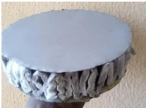
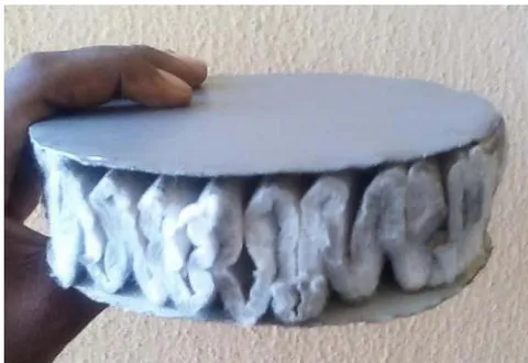
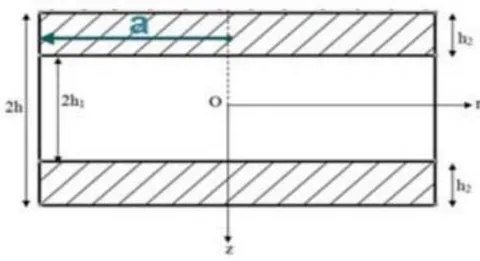
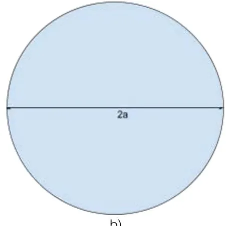
Plate section poisson ratio (v) Young's modulus E (Mpa) Material Face-sheet 0.3 5500 (Polyester resin/glass fibres) M450 Shell Core 0.41 896 (Polypropylene) Core
a) Loading Parameters
Uniformly Distributed =
Point Load = - . 2
Linearly Varying load =
b) Analytical solution (Variational Iteration Method)
The deflection function for both the simply supported and clamped sandwich circular plates were derived from the nonlinear governing differential equation modelled by Ren-huai (1980) for a circular sandwich plate, stated in expression (1). It was done using the analytical solution. Variational Iteration Method, which is an iterative method for solving the nonlinear equations of an engineering system by rewriting the given nonlinear equation as a system of coupled equations, it is capable of reducing the size of many calculations and it also gives rapid convergent successive approximations of the exact solution (He, 2005). It was executed using MAPLE (a computational software).
Having the boundary conditions as follows
At , and at
We introduced two different initial trial functions for both expressions (1a & 1b)
The Lagrangian multiplier for optimization,
Consider a general nonlinear system such as,
Its correction function takes the form
Applying the above function to the nonlinear expression in (1) to obtain its correctional function,
Substituting the value of w0 and into the correctional function (9) & (10) and iterating each time to improve the accuracy with due consideration of the Lagrangian optimization function, the value of is looped into w to get the first iteration indicated as W1 below
The iteration is repeated five times to get an accurate value of the w, a cumulative sum is applied to the iterations steps
the expression for w is gotten as,
Where the value of Df is substituted in eq. (13)
Substituting the values of q for the uniform loading conditions as stated in loading parameters,
Applying simply supported boundary conditions with uniform distributed loading, where
This resolves the value of constants A and B
Substituting value of A & B in w, we get the deflection function for a simply supported, ws
- From (15), Applying clamped support boundary conditions with uniform distributed loading, where
Substituting the value of A & B in w, we get the deflection function for a clamped support, wc
Expression (17) and (19) represents the deflection functions for the circular sandwich plate on simply supported and clamped support conditions respectively under a uniform loading.
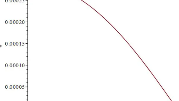
The deflection functions for point load and linearly varying loading conditions with each boundary conditions (simply supported and clamped) were also derived and the functions are plotted accordingly to get a visual representation of the deflection response across the symmetric half-length of the sandwich circular plate. The plots are shown in Figure 4 -10.
c) Finite Element Method
Here the finite element solution has been implemented using ABAQUS to verify the accuracy of
... (19)
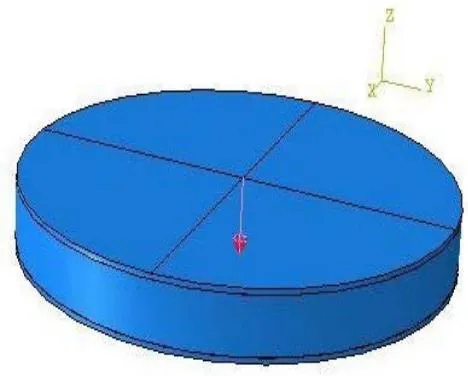
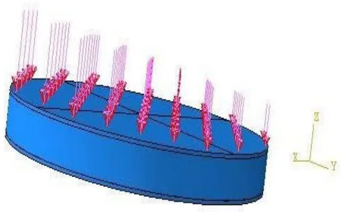
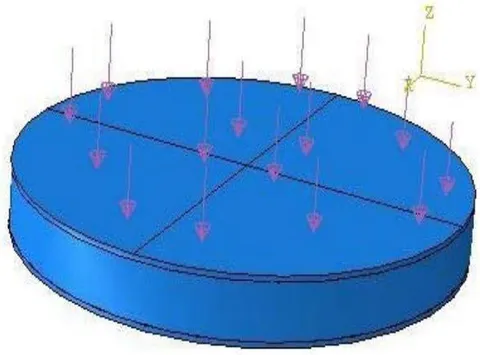
a) Concentrated load b) Linearly varying load c) Uniform load
A full model of the plate was used in the analysis, with an element size of about 0.0010 and different loading conditions of Uniform load, Point load and Linearly-varying load acting under boundary conditions of both clamped and simply supported for each loading configuration. The deflection responses under each loading conditions with the corresponding support conditions was measured and the result compared with the analytical model.
III. RESULT DISCUSSION
The resulting plots below showed the deflection behavior across the symmetric half-length of the plate, it showed the deflection curve of half the sandwich plate starting from the edge of the plate to the center at origin, under which a Clamped and simply supported boundary is considered for the plate as seen in the figures below. The curve for the Clamped boundary showed a slight tangent relationship with the x-axis indicating a dip before rising to its peak at the center of the plate, this was due to the moment generated due to its Clamped boundary conditions whereas simply supported showed a straight rise from the x-axis to its peak at the center of the plate, unlike the Clamped, there was no dip in the curve indicating the absence of moment at the boundary conditions, the curve for the simple support was quite steeper than of the Clamped support.
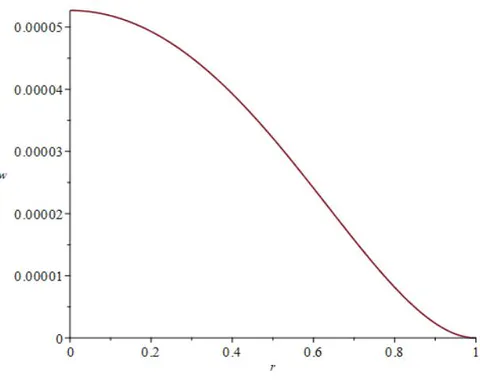
The shapes of the plot were quite similar to each other, point load is a form of uniform load only that it's concentrated at the center making a more visible impact on the plate, visual representation of this was seen in the finite element model. The clamped support generally showed a lower maximum deflection compared to the simple support, this was due to the moment resistance encountered by the load at the support as a result of its Clamped nature ensuring rigidity.
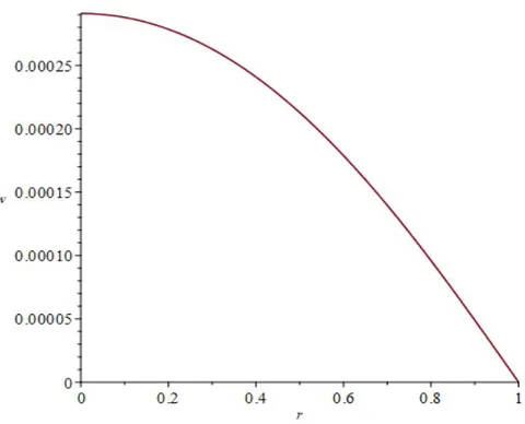
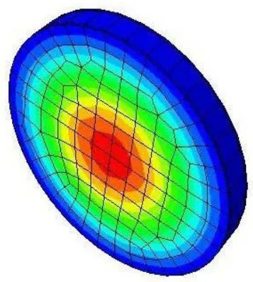
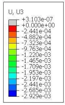
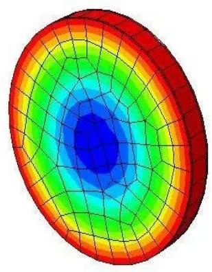
The Uniformly distributed load generates a maximum deflection for the Clamped support at a max value of 0.05mm while a higher max deflection value for the simple support at 0.25mm.
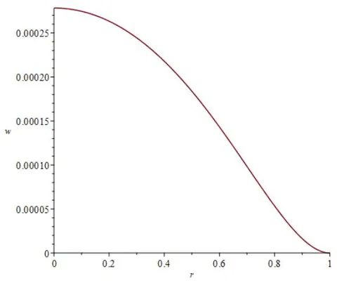
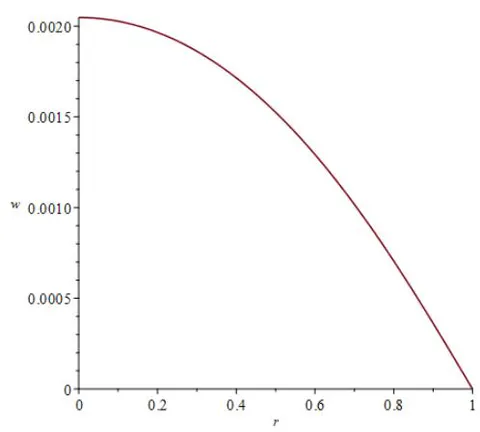
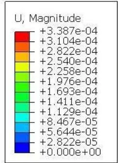
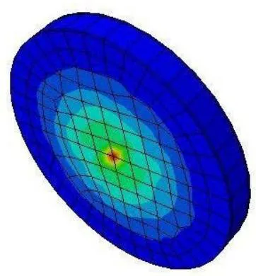
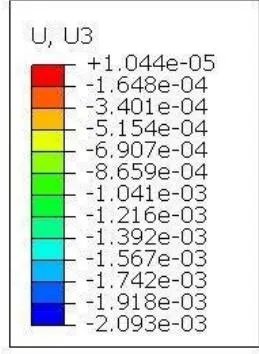
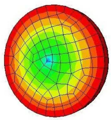
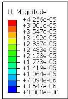
The equivalent Point load shows a higher value of the maximum deflection of 0.28mm and 2.1mm across the length of the plate for both Clamped and simply supported conditions respectively but it gives a higher value for the simply supported compared to the Clamped of which reason is due to the focus of the load at the center of the plate whilst all other factors remain constant, figure 9 shows the finite element illustration of the deflection behavior in colour variation across the elemental planar face of the plate indicating the deflection, there was a correlation in values from both method indicating accuracy of results.
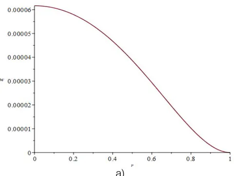
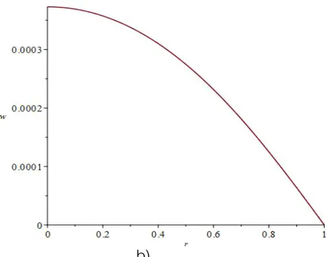
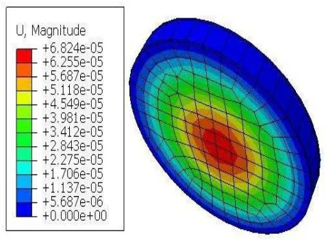
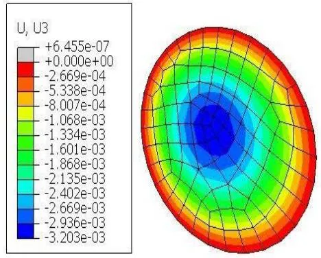
The Linearly varying load-deflection curve shows a rising deflection plot but a slight shift from the center of the plate, the analytical method could not visually represent this phenomena but the 3D plot show a shift in maximum deflection away from the center of the plate, this is a common behaviour of a member loaded with linearly varying load, the loading values. It showed a higher deflection for the simply supported compared to the Clamped, at 0.3mm to 0.06mm for both supports respectively.
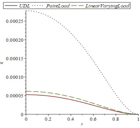
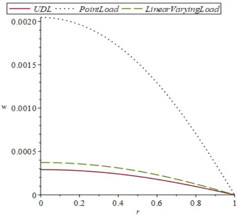
Upon combining the deflection plot of the three required loading conditions, it was observed that overall the point load had the highest value of deflection at a max of 0.28mm for Clamped support and 2.1mm for simply supported, the curve for the point load shows a steeper gradient compared to the remaining load types, but both possess similar curve structure as regards its boundary conditions.
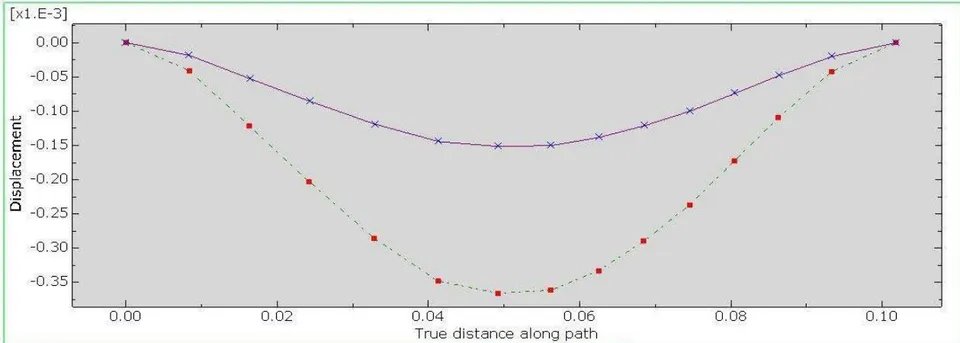
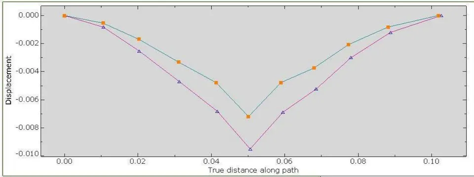
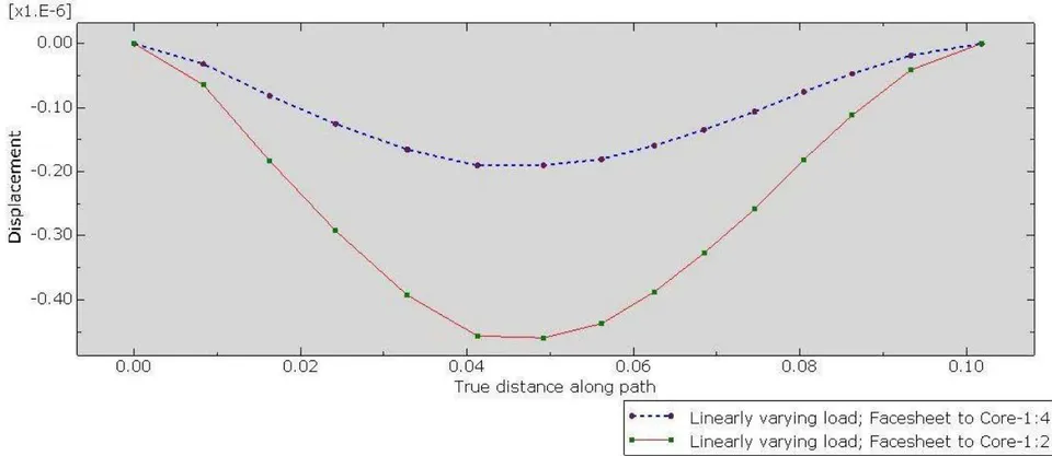
Figure 11 represents the deflection behaviour of the circular sandwich plate when the thickness of the facesheet to the core is assembled in the ratio 1:2 and 1:4 i.e. the thickness of the core is 2x and 4x the thickness of the a facesheet for each respective loading conditions. The respective loading conditions being applied to the surface of the plate include uniform, point and linearly varying load. This was done assuming the boundary conditions are Clamped.
The uniform load deflection curve for both thickness ratios show a difference in the magnitude of each respective deflections, the plate with the thickness ratio of 1:2 for facesheet to core shows a higher deflection compared to that of ratio 1:4. In subsequent variations of the loading, with point load in focus, similar symmetrical behaviour is seen in the deflection disparity of both thickness ratios, a steeper curve is seen here as corroborated by analytical method figure 8 with the plate of ratio 1:4 for facesheet to core having a lower deflection compared to that of ratio 1:2. One common trend seen in the plot for the point load and uniform load is that they both have their max deflection at the center of the plate, but the case is slightly different for the linearly varying load.
The linearly varying load experiences maximum deflection slightly away from the center of the plate as can be seen in 3D plot in finite element plots, the deflection curve shows a steeper gradient on the side of the plate with the larger load magnitude while a less steeper gradient on that of the lower load magnitude, this is seen in both variations of the thickness ratios, with thickness ratio of 1:4 having a lower deflection compared to that of 1:2.
Overall, an inverse relationship is seen between the thickness ratio and deflection of the sandwich circular plate, when the core was twice the size of the facesheet, a larger deflection was obtained while when the core was four times the size of the facesheet, a lesser deflection was obtained. This means a substantial increase in the thickness of the core in relation to the facesheet leads to a lower deflection.
IV. CONCLUSION
From the study, it can be concluded that simply supported sandwich circular plate generally experienced a higher deflection compared to the Clamped supported when placed under the various loading types considered in this research, this is due to the rigid end of a Clamped support which generates a moment to resist the bending as a result of the load. On the other hand, a Point load on a sandwich plate generates a larger deflection compared to that of uniform load and a linearly varying load, this is as a result of the load magnitude concentrated at the centre of the plate causing a focused effect as seen in both the analytical method and the Finite Element Method. A sandwich plate is quite susceptible to a point load, making it not entirely suited from that kind of loading configuration, a linearly varying load causes a slight deviation of the deflection of the sandwich plate from its centre, this would likely result in a strain on one support end compared to the other. Applications of Sandwich plates can be seen in shipbuilding, staircase landing constructions, walls, and platforms as well, offering space savings and high accuracy resulting in reduced straightening work and rapidly constructed housing using steel sandwich modules.