

I. INTRODUCTION
A monopole antenna is one half of a dipole antenna, mounted above a ground plane [33]. Applying the image theory, the electric and magnetic fields of a quarter wave monopole are those of a half wave dipole with one arm of the dipole replaced by the ground plane image. A quarter wave monopole antenna has a toroidal radiation pattern similar to its corresponding half wave dipole, with the exception that the peak direction is elevated from the horizontal plane by an angle that increases with the increase of the ground plane area (Figure 1).
In this paper, we propose a simple technique to convert a monopole antenna into a directive antenna by adding a simple dielectric material block in a certain direction with respect to the monoopole. Further studies will be required to evaluate the effects of different design parameters, such as the dielectric block dimensions, its separation from the monopole and its material on the antenna performance.
A directive monopole antenna can be used in ISM frequency bands for point-to-point communication without need to complex frequency hopping techniques that are currently used to minimize interference. The same dielectric loading technique can be used to develop UWB directive monopole antennas for UWB radar and similar applications. Moreover, a directive monopole can represent a good array element due to its simplicity of design and feeding.
II. PREVIOUS RESEARCH WORK
Different references discussed dielectric loading effects on antenna performanc. Dielectric loading decreases the required antenna size for a given resonance frequency and in general increases the antenna bandwidth. It modifies the radiation pattern and increases antenna gain. S. Lotfollah discussed different effects of dielectric loading of antennas and different applications of dielectric loading structures to enhance antenna gain, size, matching and other performance parameters . Heijun Jeong et al used a metamaterial absorber to control the radiation pattern of a monopole antenna by increasing its gain and reducing its back lobe [26]. A. MOUSAVI discussed in detail different aspects of flat dielectric radome design and its effects on the radiation pattern in his Msc. Thesis [31]. Several researchers discussed the use of superstrate layers to increase the BW and gain of microstrip patch antennas, such as K. Joshi [27], M. Elhefnawy [29], V. Saidulu [28], Kumar [30]. Ichirou Ida et al studied the efficiency-bandwidth product (EB) for small dielectric loaded antennas (DLAs) and its variation with dielectric constant [21]. T. Fortaki et al applied a rigorous full-wave mathematical analysis to investigate the effect of dielectric superstrate on resonance frequency and radiation pattern of rectangular microstrip patch antennas [23]. They proved that the resonance frequency decreases with the dielectric constant increase. O. Manoochehri et al designed an array of dielectric loaded helical monopoles and showed that by adding dielectric resonators, important parameters such as gain, side lobe level, impedance matching and axial ratio bandwidth have been improved simultaneously [16]. Detailed mathematical and experimental analyses for the refraction processes of electromagnetic waves in dielectric materials are done in the interesting chapter of "Dielectric Lens Antennas" by Carlos A. Fernandes et al, where the reader can understand why and how a dielectric body can change the direction of antenna radiation and affect its radiation pattern [24]. They differentiate between quasi-optical lenses with multi-wavelength dimensions and integrated lens antennas (ILA) with dimensions comparable to wavelength, which is our case, where FDTD analysis techniques are applicable. Design procedures and equations for different dielectric lenses are described in this reference. A research group applied those principles, designed an integrated lens patch antenna and studied the effect of different dielectric materials and lens dimensions on the radiation pattern [25].
I. Zivkovic loaded a monopole antenna uniformly from all directions by a cylindrical dielectric resonator to control its frequency response without affecting its omnidirectional radiation pattern [17]. Hongge Men et al did a similar frequency band control using a hemi-spherical dielectric resonator [18], while Ali A. Al-Azza et al extended the idea by using three dielectric resonators with different resonance frequencies [19]. Song et al proposed the use of liquid dielectrics to control the monopole antenna frequency response in a wide temperature range [20], while
Elizaveta Motovilova and Shao Ying Huang discussed in detail the performance of liquid monopole antennas. Heijun Jeong et al used a Metamaterial absorber to control the radiation pattern of a monopole antenna by increasing its gain and reducing its back lobe .
Hachi et al designed an UWB directional monopole antenna without dielectric loading. They implemented the UWB monopole on a flexible substrate and bent it on a cylindrical surface to get the directivity and enhance the radiation pattern .
None of the above mentioned and other available references discussed converting an omnidirectional monopole antenna into a directive antenna by dielectric loading. Therefore, the idea of this paper can be considered, so far, a new idea.
III. DIELECTRIC LOADING OF A UHF WIRE MONOPOLE ANTENNA
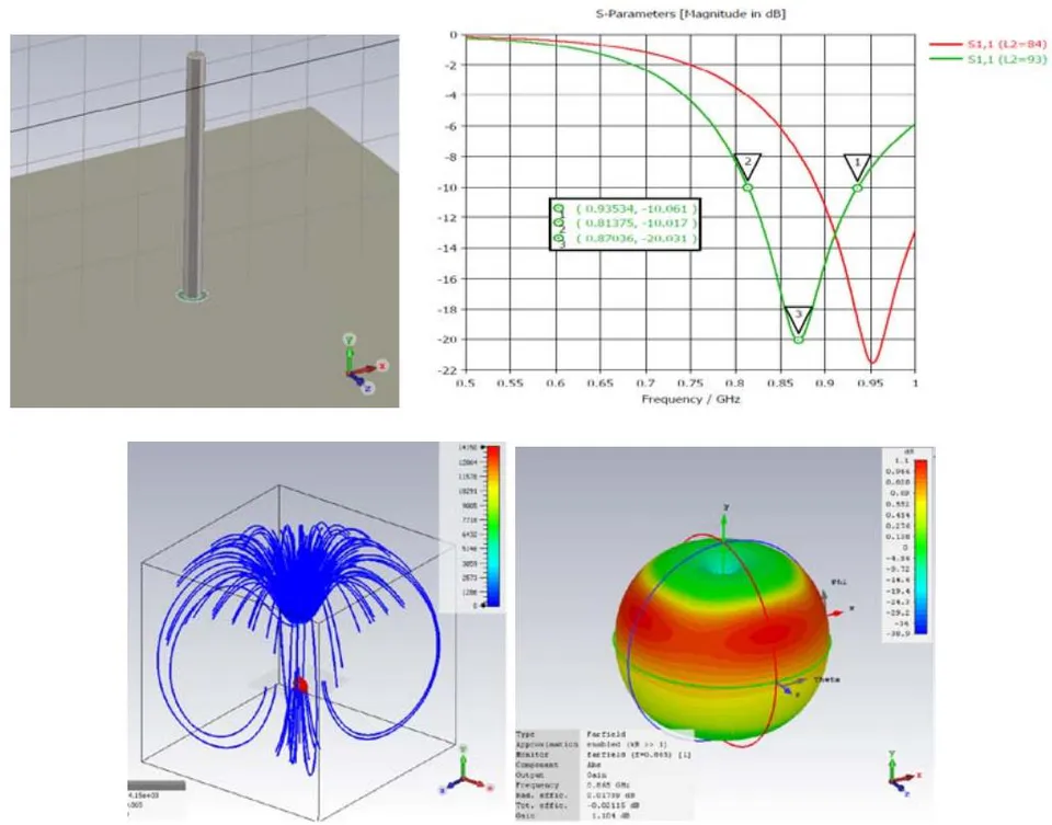
The following figure shows the performance of a UHF monopole antenna resonating at 867 MHz. It can be clearly seen the symmetry of the electric flux lines and the radiation pattern around the monopole.
Let us put a block of dielectric material beside the monopole antenna and study its effect on the radiation pattern.
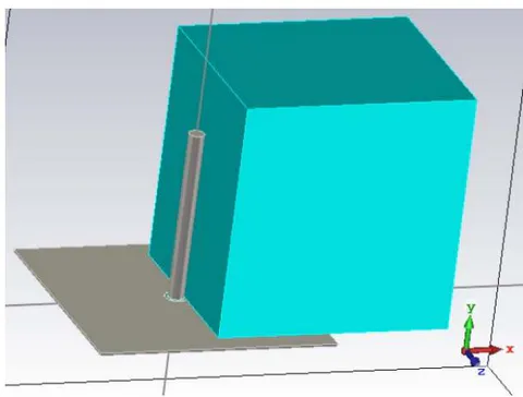
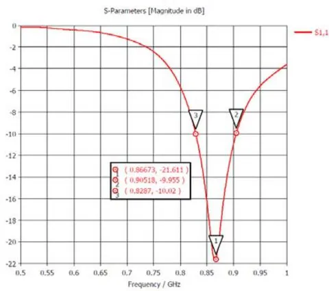
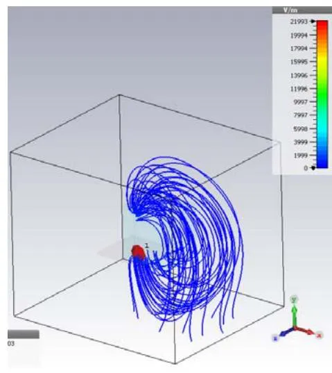
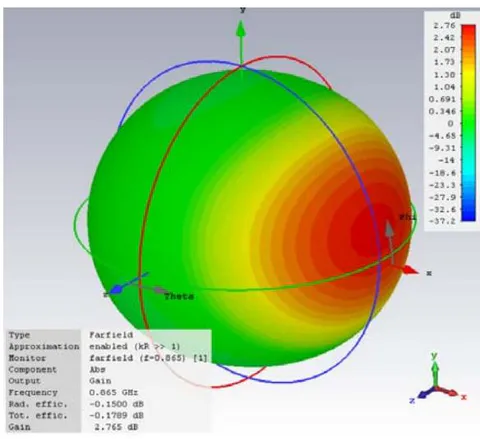
Comparing figures 1 and 2 we can recognize the following:
The monopole length required to resonate at 865 Mhz decreased due to the dielectric loading from 93mm to 71 mm.
The Q factor of the unloaded monopole antenna was 870/(935.5-813.7) = 7.158, while the Q of the loaded antenna is 866.73/(905.18-828.7) = 11.333.
The electric flux lines have been concentrated in the dielectric material instead of being uniformly distributed in all direction in the first case.
The monopole antenna radiation pattern has been concentrated in the direction of the dielectric block to give a dirjective monopole antenna, instead of the symmetric toroidal pattern of the unloaded monopole antenna.
The antenna gain increased from 1.104 dB to 2.765 dB.
The radiation efficiency of the unloaded monopole antenna was .
The radiation efficiency of the loaded monopole antenna became .
The total efficiency of the unloaded monopole antenna was .
The total efficiency of the loaded monopole antenna became .
The dielectric loading caused a minor decrease in the antenna efficiency.
The differences between the omnidirectional monopole antenna and the dielectric loaded directive monopole antenna can be summarized in the following table.
| Performance parameters | Units | Omnidirectional monopole antenna | Directive monopole antenna | Notes |
| Resonator length | mm | 93 | 71 | Shorter resonator |
| Q | - | 7.158 | 11.333 | Higher quality |
| Gain | dB | 1.104 | 2.765 | Gigher gain |
| Radiation efficiency | % | 99.78 | 96.6 | Minor decrease Due to dielectric loading |
| Total efficiency | % | 99.166 | 95.964 |
IV. DIELECTRIC LOADING OF A UHF PRINTED MONOPOLE ANTENNA
To demonstrate the applicability of the same idea on printed monopole antennas and to get more insight in the performance of directive printed monopole antennas, another UHF model has been simulated on the popular 1.6mm thick FR4 substrate.
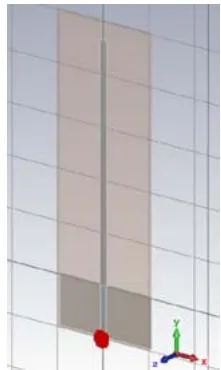
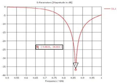
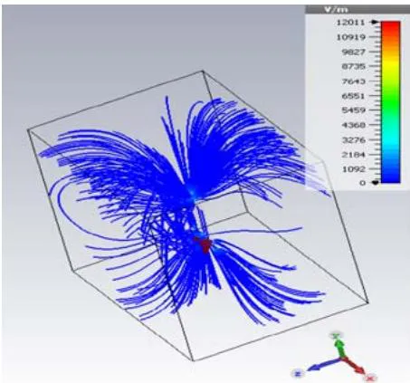
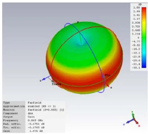
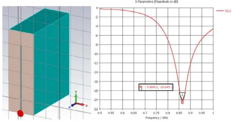
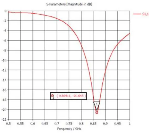
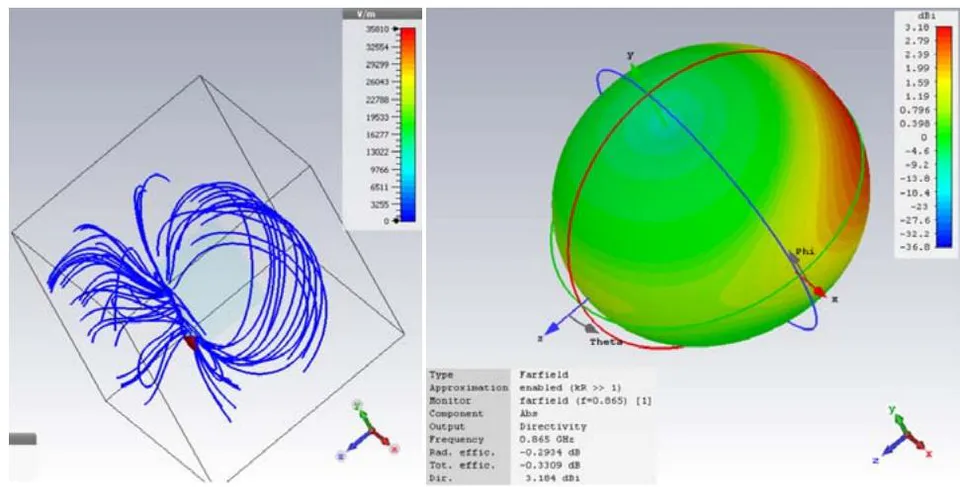
Comparing figures 3 and 4 we can build the following table.
| Performance parameters | Units | Omnidirectional monopole antenna | Directive monopole antenna | Notes |
| Resonator length | mm | 93 | 76 | Shorter resonator |
| Q | - | 8.665 | 9.329 | Higher quality |
| Gain | dB | 1.876 | 3.184 | Gigher gain |
| Radiation efficiency | % | 96.048 | 93.467 | Minor decrease Due to dielectric loading |
| Total efficiency | % | 96.017 | 92.664 |
V. PUTTING THE DIELECTRIC BLOCK IN THE OPPOSITE DIRECTION
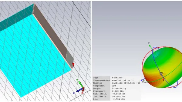
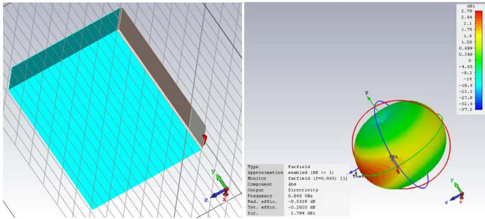
If we put the dielectric block in the oppsite direction, logically the beam will be steered by 180 degrees as shown in the following figure.
VI. DIELECTRIC LOADING OF A 2.4 GHz PRINTED MONOPOLE ANTENNA
The 2.4 GHz ISM band is one of the most utilized and crowded frequency bands; due to the existence of many commercial communication and control systems, such as cordless telephone, baby monitors, WiFi standards 802.11b, 802.11g and 802.11n, ZigBee/IEEE 802.15.4-based wireless data networks, Bluetooth, Bluetooth_LE, wireless microphones, headphones and speakers and others. Due to this over utilization of this frequency band, interference probabilities are very high. This causes the system designers to apply complex frequency hopping, data encryption, error detection and correction techniques. Moreover, device pairing in Bluetooth systems requires complex protocols that need long times to secure pairing and avoid interference.
If we ensure a directive path between the transmitter and the receiver, interference probabilities will decrease and Bluetooth pairing processes can be simpler and more secure. In most cases, frequency hopping will be less mandatory.
The following figure shows the performance of a 2.4 GHz printed monopole antenna covering the frequency band 2.4 to 2.5 GHz. It can be clearly seen the symmetry of the electric flux lines and the radiation pattern around the monopole.
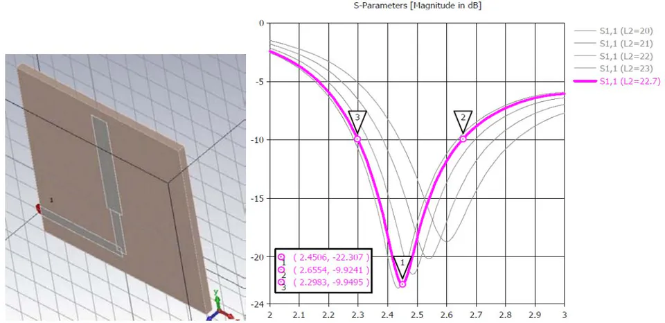
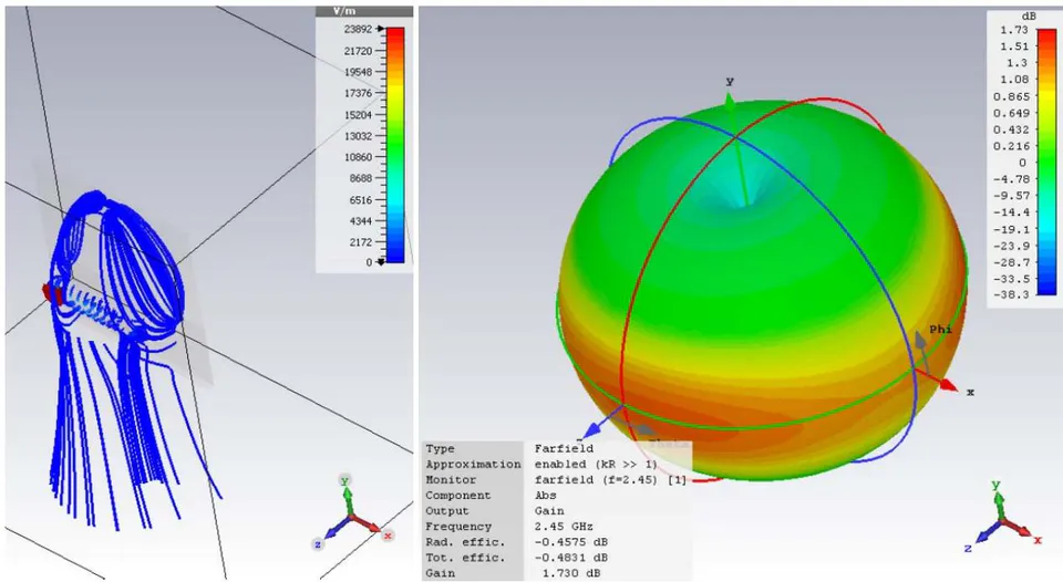
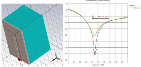
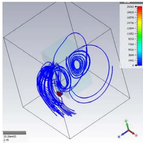
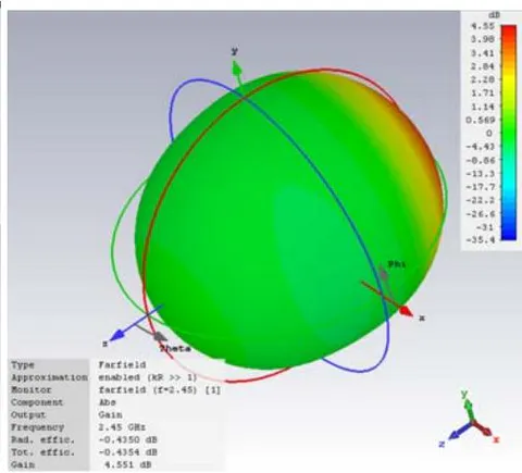
Comparing figures 6 and 7 we can build the following table.
From this table we can conclude that the dielectric loading needs a shorter resonator, increases the BW and the efficiency. The directive gain reaches more than 4.5 dB.
| Performance parameters | Units | Omnidirectional monopole antenna | Directive monopole antenna | Notes |
| Resonator length | mm | 22.7 | 20.2 | Shorter resonator |
| Q | - | 6.8625 | 3.274 | Wider BW |
| Gain | dB | 1.73 | 4.55 | Much Gigher gain |
| Radiation efficiency | % | 90 | 90.469 | Higher efficiency |
| Total efficiency | % | 89.47 | 90.46 |
VII. DIELECTRIC MATERIALS TO BE USED
In the above models, a dielectric material with and was assumed. These are typical electrical parameters of composite materials used in 3D printers, such as PLA, ABS and PET [4, 5 and 6]. Such materials are easily found in the market at economical costs. In this section we shall briefly study the electrical parameters of common dielectric materials used in 3D printers.
Veselý et al measured the relative permittivity of dielectrics by measuring the capacitance of a circular parallel plate condenser with diameter d and thickness w of the material under test [4] and applying the simple formula:
Unfortunately, different measuring methods gave different results for the same materials, even by the same reasurcher. Naturally, other references gave different results. Such as those of Boussatour et al [6]. However, the range of variation of dielectric constants of those materials is between 2 and 3.5, and the dissipation factor ranges between 0.001 and 0.022.
VIII. CONCLUSION
Quarter wave monopole is an omnidirectional antenna with omnidirectional radiation pattern. It can be changed into a directive antenna by dielectric loading.
The dielectric material block concentrates the electric field of the antenna and reradiates the waves in its direction increasing the antenna gain. The effects of dielectric loading increase with its relative permittivity [15].
The dielectric loading shortens the required monopole length and enhances some of its performance parameters.
The dielectric block can be made of commercially available materials such as those used in 3D printers, whoes dielectric constants range between 2 and 3.5. The exact dielectric constants of those materials are still subject to trials for accurate measurement.
Three cases have been studied in this paper; an UHF wire monopole, an UHF printed monopole and a 2.4 GHz printed monopole. Further studies are still required to evaluate and optimize UWB directive monopole antennas and directive monopole arrays.
Further investigations should be done to determine the minimum required dimensions of the dielectric block to give a certain radiation pattern in every frequency band.
Further research work should be done to study the design of directive UWB monopole antennas and antenna arrays with directive monopole elements.