
Three are today known basic of the type of the electrostatic generators, utilized for obtaining the high voltages. The work of these generators is based on the use of laws of electrostatic induction. These are the dropper of Calvin [1], generator of Van de Graaf[2] and the electro-form generator of Wimshurst [3].
Originally entire installation has neutral charge. It is unknown in view of the symmetry of installation and absence of charge, on which of the jars positive or negative charge will be accumulated. A small potential difference always is present because of different external actions between the left and right side of the installation, therefore the installation requires no starting charging of jars for the starting of system. By the force electrostatic induction ferrules direct in the reservoir with the water in that place, under which they are located, opposite charges. As a result a quantity of charges on the opposite edges of reservoir becomes different. After falling, drop they fall into the jar, which corresponds to its charge, thus increasing its charge, which creates still larger electric field near the rings, strengthening the separation of static charge and a potential difference between the banks it grows.
II. ELECTRIC GENERATORS OF MENDE
a) Dropper of Mende
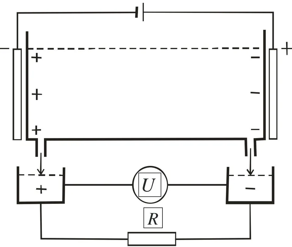
If we on the electrolyte put the electric field (Fig. 3), thus it is polarized, in this case on the left side the baths will be collected anions, and in its right part cations will be collected. Charged anions produced through the openings in the lower part of the bath and cations fall into the separate baths, forming two battery terminals, which manufactures current, if we between these poles include load.
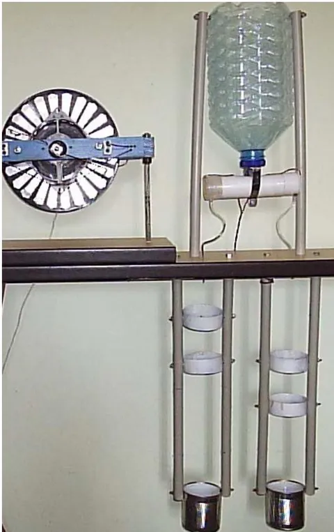
A general view of the Mende dropper is shown in Fig. 4. Next to the dropper is an electroform generator, from which voltage is applied to the electrodes of the dropper.
b) The
Generators for separation and accumulation examined above of charges are used the laws of electrostatic induction, and magnetic fields in these processes of participation do not assume. Hall's law is at the same time known, who gives the possibility to separate the moving charges [1].
In the simplest examination the Hall effect is represented in Fig. 5. Through that conducting plate in the normal direction passes magnetic field with the induction B and it flows through the same plate the electric current with the density j under the action voltage E. It will slant magnetic field charge carriers different signs to one of the faces of plate.
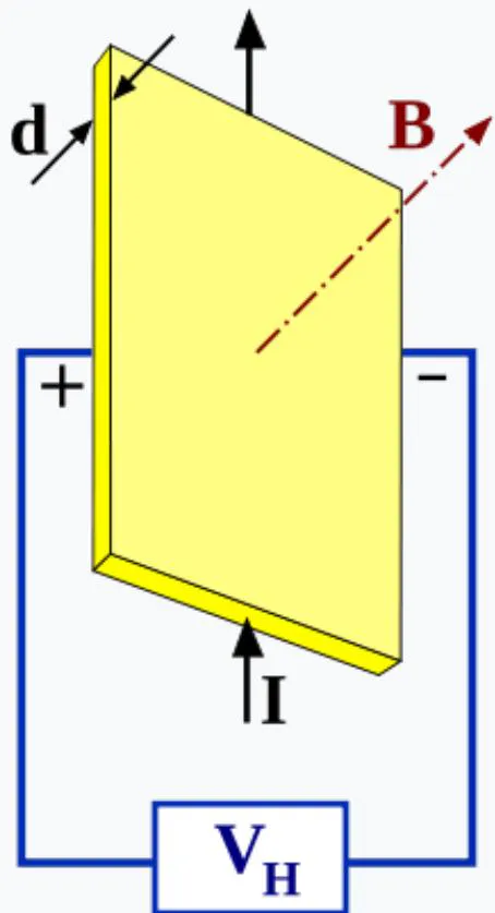
Thus, Lorentz force it will lead to the accumulation of negative charge near one face of plate, and positive- near the opposite face. The accumulation of charge will continue to those times, thus far arisen the electric field the charges it does not compensate for Lorentz force:
where e - electric charge.
Usually Hall effect is used for measuring the magnetic field, but it can be used also for the separation of charges in the fluxion, for example to water. In the water there are always ions the dissolved in it salts. And it is possible to divide them with the aid of the Hall effect. If water will move normal to the direction magnetic field, then the ions of different signs will be accumulated on the different sides of flow. Dividing further flow to two parts, it is possible to obtain two separate flows, in which will be concentrated the ions of different signs. The circuit of separation of charges the method indicated is in Fig. 6.
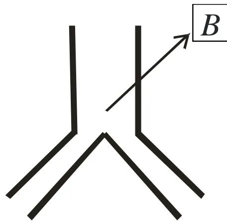
Gathering these flows into the different capacities, as is done in Calvin's dropper, it is possible to create the electrostatic generator (Fig. 7).
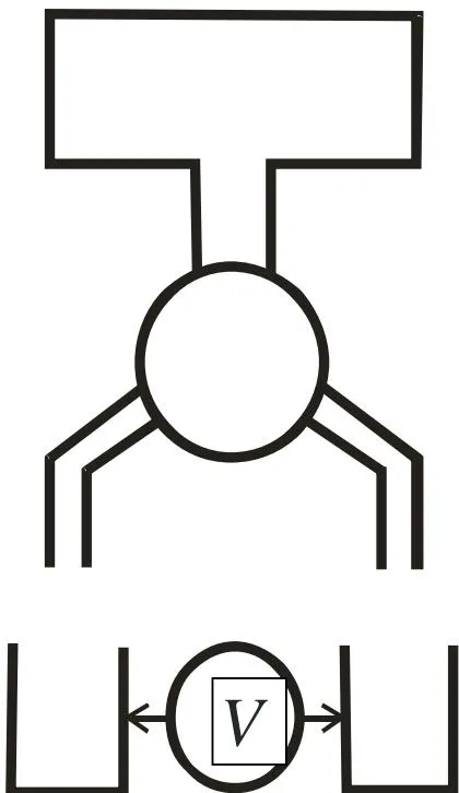
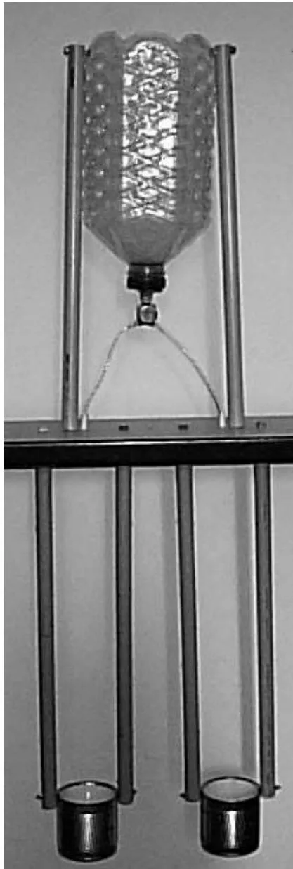
On the experimental installation with the use of two annular samarium magnets, between which magnetic induction composed 0.5T, was obtained a potential difference 50 kV.
The common form of electrostatic generator with the magnetic separation of charges is represented in Fig. 8.
c) Parametric generators of Mende
If there is a capacitor, whose capacity C, and this capacitor it is charged to a potential difference U, that the energy, accumulated in it, is determined by the relationship
But charge Q, accumulated in the capacity, is equal
From relationship (2.1) it is evident that if the charge, accumulated in the capacity, remains constant, then voltage on it can be changed by changing the capacity. In this case is fulfilled the relationship
whereof and - instantaneous values, and and - initial values of these parameters.
The voltage on the capacity and the energy, accumulated in it, will be in this case determined by the relationships:
Coefficient
can be named by the multiplication factor (transformation) of the constant voltage.
The schematic of voltage transformer, realizing the principle examined, is represented in Fig. 9
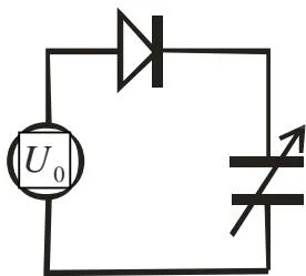
In this diagram to the variable capacitor by means of the diode the dc power supply is connected
The incremental voltage, which can ensure this transformer, is determined from the relationship
As follows from the relationships (2.3) and (2.4) with the decrease of capacitance of capacitor on it increases not only voltage, but also the energy, accumulated in the Ger.
It should be noted that this transformer can work only in the regime of an increase in the voltage, since with the attempt to obtain the decrease of voltage across capacitor this cannot be made for that reason, that the diode the straight connection of the voltage source to the capacitor ensures and therefore voltage across capacitor decrease cannot.
An increase in the energy, accumulated in the capacitor, with a change in its capacity is determined from the relationship
With a mechanical change in the capacitance of capacitor, the increase in the energy indicated ensures the spring mechanical energy source, Properties of the transformer of constant voltage is possible to use for creating the high-voltage source of the direct current, whose diagram is given in Fig. 10.
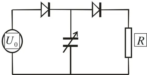
In this diagram is present still one diode and load resistance R.
In the initial state the capacitance of capacitor is equal , and voltage on it equally . At this time through the load resistance the current flows
In this case the energy, obtained by capacitor from the voltage source, comprises
As soon as capacitance of capacitor will begin to decrease, the secondary voltage, assigned by the relationship will appear on it (2.5). This secondary voltage through the right diode enters the load resistance R. The additional energy, isolated in this case during the load resistance, is determined by the relationship (2.7).
The operating principle of the generator examined is such to the operating principle of the valve water pump, whose schematic is represented in Fig.
With the displacement of piston downward left release valve is opened, and water is sucked in into the cavity of pump. With the displacement of piston upward the water through the right release valve is ejected outside.
The role of valves in the schematic of the described generator diodes play, while the role of cylinder with the being moved piston performs variable capacitor.
Hence it follows that the basic problem of the creation of the proposed generator is the development of the capacitor, whose capacity changes with mechanical method. In this case the capacitor must have the great significances of initial and final capacity and with the large relation of these values. This question can be solved by the way of using the technology of the creation of the ceramic capacitors, when titanate of barium, which has very large dielectric constant, is used as the dielectric between the capacitor plates. The construction of the generator, in which is used the principle indicated, it is shown in Fig. 12.
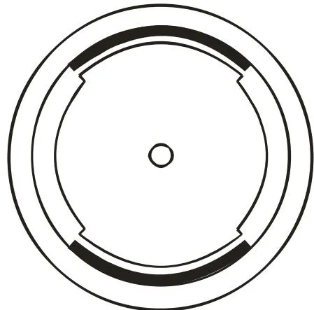
In the given construction there is a figured rotor, and inserts from titanate of barium are located on the internal surface of cylindrical stator.
During the record of this formula are taken into account the fact that in one revolution of rotor it occurs two cycles of a change in the capacity between the rotor and the stator.
The substitution of the assigned parameters into the formula (2.9) gives the power 34 kW.
The output voltage, which manufactures generator, calculated according to the formula (3.3) it will comprise 1 MV. This voltage will be developed between the stator-rotor unit when the capacity between them is minimum. In order in this case to avoid electrical breakdown, the internal cavity of generator must be filled with air or another gas under the high pressure.
None of the existing generators can ensure such high voltage without the use of the step-up transformers and rectifiers. Large simplicity of construction is the very great advantage of this generator.
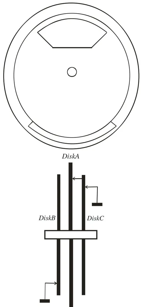
The type of generator in the section is shown in Fig. 13.
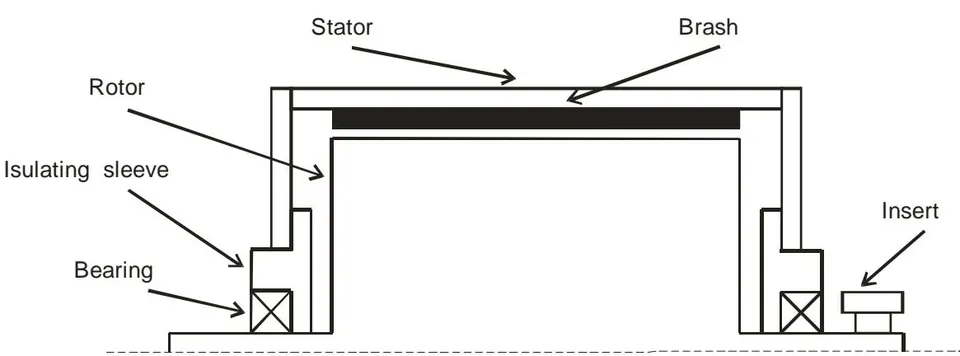
The insulating bush is located between the axis of rotor and the housing of stator. In this bushing the bearing is located. By lower its edge bushing slides along the axis of shaft, ensuring the vacuum seal between the internal cavity of generator and the atmosphere. The insert from titanate of barium is located on the internal part of the stator. The electrical contact between the axis of rotor and the external circuits brushes ensure.
d) Electro-form generator of Mende
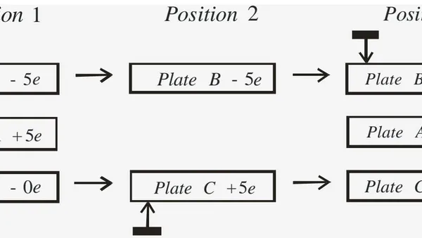
The schematic of the work of elektro-form generator Mende is depicted in Fig. 14.
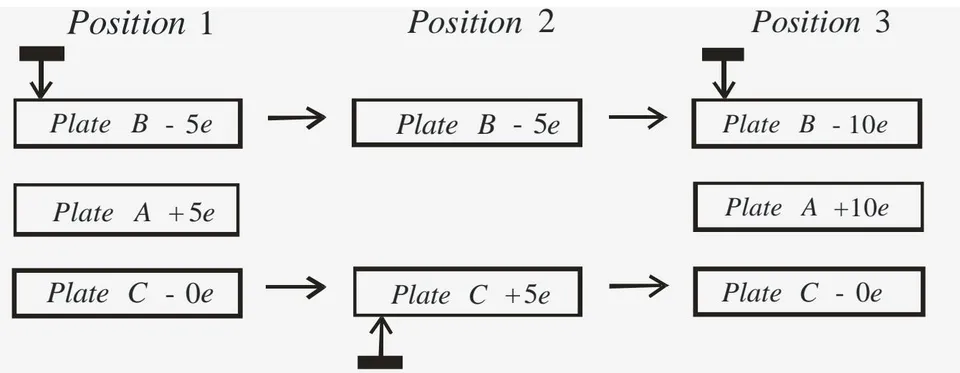
There are three plates of parallel-plate capacitor A, B and C, from which the plate B and C they can move in the direction, indicated with pointers, while average plate A it remains fixed.
In the position 1 the plate B by means of the contact sliding on it is connected with the earth. Plate C also by means of the sliding contact, which moves together with it, is connected with the plate A. On the plates there are designations, which indicate the instantaneous value of charges on them in the arbitrary units with the indication of the sign of charge. Initial magnitude of the charge can be other and depends on the initial conditions.
Let us assume that in the initial position plate A bears on itself the charge +5e, and plates B and C begin to synchronously move to the right. In this case the plate v loses contact with the earth, and on it remains the charge - 5e.
In the position 2 the plate B preserves charge to -5e, and plate C acquires contact with the earth and on it is induced the charge +5e. After that, plates B and C continue to move in the direction indicated by the arrows.
In the position 3 of the platesCand A they are connected with the aid of the sliding contact, which moves together with the plate C, and plate B is connected to the earth. In this case the charge +5e from the plate C overflows into the plate A and its charge it becomes equal +10e, and the charge of plate C becomes equal to zero. In this case the plate A, which received the booster charge +5e, induces in the plate into the charge -10e, i.e. in comparison with the position 1 the charges of plates A and B also in double.
III. CONCLUSION
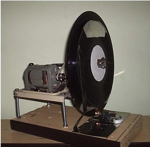
In the article the survey of the existing constructions of high-voltage electrostatic generators is carried out. Are described the new types of the generators of Mende, the using laws of electrostatic induction and the tests of the experimental are carried out the models of such generators.