I. INTRODUCTION
The discoveries made in the pre-salt region (a geological formation of continental shelves) in Brazil are among the world's most important in the past decade. In this region, there is a considerable amount of good quality oil and this reality puts Brazil in a strategic position for the global demand for energy [1]. The discovery of this region brings several technological challenges for the oil and gas exploration. The corrosion process in this region occurs under specific conditions. Some of them are high temperatures between and , the presence of gases such as carbon dioxide and hydrogen sulfide , oil formation water, high pressure, leaving the operating environment very hostile[2]. The main characteristic of the pre-salt region is the high content of sodium chloride found there. This , and dissolved in the oil field formation water can accelerate the corrosion of metallic materials used for the oil exploration in the pre-salt region. Another concern for this operation is the environmental impact that can occur if these materials fail. Cheaper materials such as carbon steels are a good choice but there is a problem related to them: The difficulty in adding corrosion inhibitors for carbon steel pipes in offshore oil extraction at great depths. This has led to the increased use of corrosion resistant alloys[3]. Of all types of corrosion, localized corrosion, especially pitting corrosion, is the most common in marine waters and difficult to control. Currently, the oil and gas industry is concerned about the environmental impact caused by oil leaks in the marine ecosystem. This type of accident can be prevented using materials more resistant to the environmental conditions found in the pre-salt region. There are two types of technological challenges for the exploration of oil and gas contained in the pre-salt region: the other challenge consists of drilling the well as far as the reservoir, crossing water layers, sediment, and salt. Each layer with a different behavior at temperatures ranges from to under high pressures and corrosive gases, all these conditions acting together. The way back to the surface must also be considered.
All the oil and natural gas extracted from the well will be transported through the pipelines, and the material from which the pipes are made must resist all adverse conditions to avoid oil leaks. The second challenge is horizontal and consists of transporting the oil and gas from the production area to the coast, localized about away from the well location [1]. In summary, it is a set of problems that begins with the well's depth, passing by the coating when drilling into soft sediments through the salt layer to reach a very high temperature and pressure environment saturated with corrosive gases already mentioned[4]. Corrosion resistant-alloys such as super austenitic stainless steels are a great choice when considering the severe conditions of presalt. Due to their high chromium, nickel, and molybdenum content, it is expected that this kind of material presents more corrosion resistance in the presalt conditions than the conventional stainless steels. Some authors have already studied the corrosion resistance of austenitic stainless steel and other materials regarding the effect of . For this paper, the effect of the oil field formation water with and without was studied, taking into account two austenitic and two super austenitic stainless steels for later comparison. Two electrochemical techniques, one potentiodynamic and the other potentiostat were used to evaluate the corrosion resistance for these materials in artificial oil formation water.
a) Materials
For this research, the materials used were the AL-6XN PLUSTM super austenitic stainless steel, the 904L super austenitic stainless steel, and the 300 series austenitic stainless steels AISI 316L and 317L. The chemical composition of the materials studied presented in Table 1 were measured in an Optical Emission Spectrometer (PDA-7000 SHIMADZU). The Pitting Resistance Equivalent Number was calculated using equation 1.
| Alloys | C | N | Mn | Si | Cr | Ni | Mo | PREN |
| 316L | 0.030 | 0.05 | 1.65 | 0.41 | 17.2 | 10.7 | 2.2 | 26 |
| 317L | 0.024 | 0.06 | 1.49 | 0.40 | 17.8 | 12.3 | 3.5 | 31 |
| 904L | 0.027 | 0.10 | 0.74 | 0.66 | 19.5 | 24.3 | 4.5 | 37 |
| AL-6XN PLUSTM | 0.021 | 0.24 | 0.35 | 0.32 | 21.8 | 25.8 | 7.6 | 54 |
b) Characterization of the Samples
The samples in the as-received condition were characterized using x-ray diffraction (XRD) by Synchrotron Light (energy 12 keV) to detect the phases. ICDD database (International Centre for Diffraction Data) was used to identify the peaks of the phases. A Gleeble was used to fix the samples. The measurements were carried out at the Brazilian Synchrotron Light Laboratory in the city of Campinas-SP in Brazil. For this characterization, the shape and dimensions of the samples are shown in Figure 1.
c) Electrochemical Tests used
To evaluate the corrosion behavior of the materials, two electrochemical techniques were used: a potentiodynamic technique (linear polarization test) and a potentiostatic technique (potential steptest), one complementing the other. Firstly, the linear polarization technique was used to evaluate the effect of on the corrosion behavior of the samples. The dimensions of the samples were with an average exposure area of . The samples were mounted in cold resin and ground using SiC paper up to 600 mesh, washed in distilled water, and then blow-dried. An adapted cell was used with two gas inlets, one for and one for . The cell also contained an input for a pH reader, in addition to the classic inputs for the three main electrodes (reference, working, and counter electrodes) in addition to a gas outlet (see Figure 2). The electrodes used were the samples (working electrode), as counter electrode a platinum electrode , and the reference electrode used was the silver chloride silver (Ag/AgCl/Cl ) saturated with KCl. The electrolyte used (artificial oil field formation water) was named by Petrobras of TQ 3219 which composition is shown in Table 2.
| Reagents | CaSO4 | MgCl2 | NaHCO3 | NaCl |
| C (g/L) | 0.516 | 4.566 | 0.425 | 29 |
First, the solution was deaerated with gas to simulate the pre-salt environment (absence of free ) that could interfere with the results. The gas was bubbled into the solution until a pH of . After this procedure, the solution was bubbled with until saturation . In this procedure, the electrolyte became acidic. gas in contact with an aqueous solution (oil field formation water) forms acids that react with the metallic elements of the alloy [9]. A potentiostat (AUTOLAB PGSTAT302N) connected to a microcomputer was used for both techniques. The software NOVA 1.9 was used to obtain data from the linear potential curves. Before the measurements, the samples were immersed for in the solution to determine the open circuit potential (OCP). The sweep of the polarization curves was to from the OCP with a sweep rate of . After linear polarization tests, the samples were washed with water and sprayed with alcohol to clean the surface. Scanning Electron Microscopy (SEM) micrographs on the surfaces of the samples were obtained after corrosion tests for later comparison. The corrosion tests were reproduced in triplicate.
The potential step technique (potentiostatic technique) was also used to evaluate the corrosion behavior of the samples for the solution of artificial oil field formation water, this time with no and no . This test was intended to evaluate only the effect of the artificial oil field formation water on the surface of the samples. For this test, the samples were mounted in cold-curing epoxy resin, ground up to 600, rinsed with ethanol, and blow-dried before each measurement. The samples had the dimensions of mm. To reduce crevice corrosion on the epoxy/steel, the specimens were coated with a lacquer leaving an exposed area of . A three-electrode cell configuration was used. A saturated silver/silver chloride (Ag/AgCl) as reference electrode and a platinum electrode as a counter electrode were used. The electrolyte used was the same used in the linear polarization test (see Table 2). A potentiostat (AUTOLAB PGSTAT302N) connected to a microcomputer along with the software NOVA 1.9 was used. Before the measurements, the samples were immersed for in the solution to determine the open circuit potential (OCP), the same procedure used before. Subsequently, the potential was increased in steps of every one hour until a breakthrough current density was attained. The pitting corrosion initiation potential was defined when the current density reached values above [10]. After the tests, the samples were examined by SEM to confirm the presence of pits on their surfaces. The tests were carried out in triplicate at (room temperature).
II. RESULTS AND DISCUSSION
a) Characterization of the Samples for the as-received Conditions
The X-ray diffractogram pattern for the 316L and AL-6XNPLUSTM steels can be seen in Figure 3. For both sheets of steels, the main phases detected were the matrix phase (austenite) and some ferrite peaks, indicating that both materials were not in the solution annealed condition. No other phases were detected for the analyzed angle range (25-79°). For this measurement, a synchrotron light radiation source ( ) was used. This measurement was not possible for the 317L and 904L steels due to a manufacturing problem of the samples.
b) pH Study of the Solution
Firstly, the solution used in the corrosion tests (artificial oil field formation water) was studied. The solution was deaerated by bubbling to simulate the absence of free oxygen from the pre-salt layer. Figure 4 shows the results for the study of the solution (called TQ3219 by Petrobras). The stabilization of indicates that the electrolyte is deaerated and subsequently saturated with . All the chemical reaction that happens when bubbling CO2 in the solution is described in our previous work [4].
c) Corrosion Evaluation using a Potentiodynamic Technique
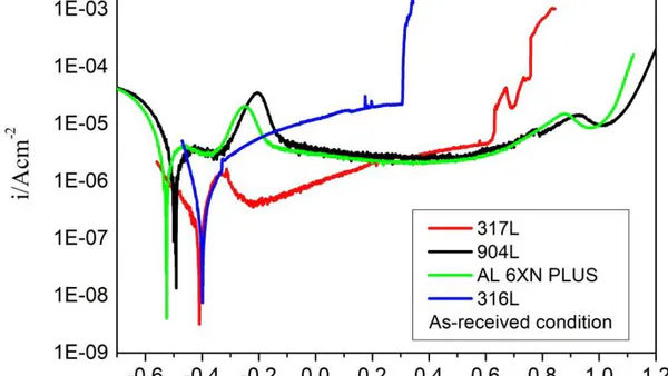
Before the linear polarization tests, the OCP of the samples was measured. The result is shown in Figure 05. The OCP of the super austenitic steels (AL-6XN PLUSTM and 904L) stabilize in 5 minutes. For the other austenitic steels (316L and 317L), the stabilization time is longer, e especially for the 317L steel. After 30 minutes of immersion, all the OCP are stabilized. Figure 6 shows the linear polarization curves for the steels in the as-received condition. The linear polarization tests aim to verify the formation of passive film or not on the alloys surfaces[11]. For this test, all the samples were immersed in the solution used (artificial oil field formation water) saturated with . The super austenitic stainless steels AL 6XN PLUSTM and 904L showed a good corrosion resistance. After reaching the corrosion potential (around -0.5 V), a passive film is formed and broken at -0.34 V until they reach a passivation peak around -0.20 V. After this potential, there is the formation of another passive layer that remains until the potential of +0.89 V where there is a slight breakdown of this layer and another passivation. After reaching a potential of +1.02V (pitting potential), there is an increase in current density, the transmissive region, since the potential is too high (above +1.0 V). It is possible to observe that the electrochemical behavior for the super austenitic steels studied in this work is very similar. Their passive regions are quite stable. The increase of current density after +1,0 V can be associated with oxygen evolution, reported in the literature[12]. The 317L steel also showed a good corrosion resistance. The formation of its passive layer is not so stable as the passive layers of the super austenitic steels; even so, the current density in the passive region remains low, in the order of . Its pitting potential is around +0.61 V. The 316L steel did not present any passivation since the anodic current increased with time. This steel presented the highest anodic current rate (in the order of ) if compared with the other steels. Its corrosion potential is similar to the corrosion potential of 317L steel (+0.40 V). 316L steel presented the lowest pitting potential (+0.30 V), indicating that its corrosion resistance is not very efficient. The reduction in anodic current density is associated with the passive film as a protective barrier against corrosion. The super austenitic steels AL-6XN PLUSTM and 904L showed a reduction in their anodic current, while the austenitic steels 316L and 317L showed an increase in anodic current with time. This result shows that the passive film of super austenitic steels is more stable. This effect can be attributed to the high levels of alloying elements such as Cr, Mo, and Ni. According to Sedriks, on a polarization curve, the greater the difference between the pitting potential and the corrosion potential ( ), the more resistant to corrosion the material is [13]. Table 2 shows the corrosion potential values, pitting potential, and the difference between them for the studied steels. The interval is higher for the super austenitic steels, which confirms their high performance about corrosion. The 316L steel had the lowest value for , indicating that it is not a suitable material for applications that require good CO2 corrosion resistance. More detailed work on corrosion using austenitic stainless steels by the authors of this research can be found in [4].
| Alloy | E(corr) | E(pit) | ΔE |
| 316L | -0.41 | 0.30 | 0.71 |
| 317L | -0.41 | 0.61 | 1.02 |
| 904L | -0.49 | 1.02 | 1.51 |
| AL-6XN PLUSTM | -0.53 | 0.99 | 1.52 |
After the linear polarization tests, SEM of the surfaces of the steels was carried out. The only material that presented pits on its surface was the 316L steel, as shown in Figure 7. Several factors may have influenced this form of corrosion for the 316L steel. Among them, one can mention: inefficiency of the passive film, pH of the solution, chloride content in the solution, effect of . The action of the chloride ion in an acid medium caused by the reaction of gas in an aqueous medium can accelerate the localized corrosion process.
d) The Corrosion Resistance of the Steels in Artificial Oil Field Formation Water
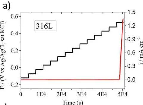
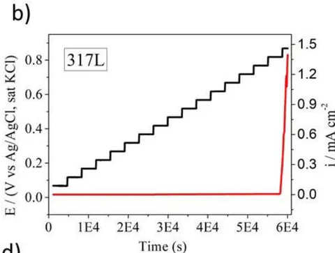
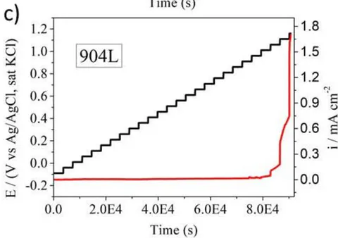
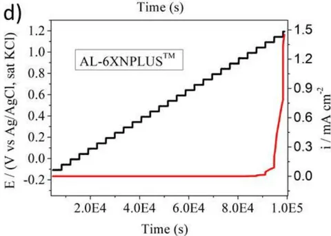
The samples in the as-received condition were submitted to another electrochemical technique called potential step. This time, no or was used in the solution (artificial oil field formation water). The investigation using this technique is in agreement with the linear polarization experiments where the 904L and AL-6XN PLUSTM austenitic stainless steels had excellent pitting corrosion resistance when compared with the other austenitic steels (316L and 317L). Figure 8 shows the results of potential step for the 316L, 317L, 904L, and AL-6XN PLUSTM alloys, respectively. The graphs are of type double Y-axis, where the potential (V vs. Ag/AgCl, sat KCl) and the current density are plotted on the Y-axis, and the time (s) is plotted on the X-axis. Every potential step was maintained for one hour. If nothing happened on the passive film, then a new step was reached by an increment of . The pitting potential of each alloy was achieved when the current density reached values above , as shown on the graphs. So there was an abrupt increase in the current density indicating the breakdown of the passive film. The time to achieve the pitting potential depends on the film resistance of each alloy. The more resistant the passive film, the more time is needed to reach the pitting potential. The pitting potential for the 316L steel presented the lowest value , while the pitting potential for the 904L and AL-6XN PLUSTM steels presented the highest value and V, respectively). The pitting potential for the 317L steel showed an intermediate value . Table 3 shows the pitting potential and the time to achieve it for each alloy. It was necessary more than one day for the sample of the AL-6XN PLUSTM steel to reach its pitting potential. This result shows how resistant this material is to the conditions used. On the other hand, the 316L steel presented the lowest time to reach its pitting potential. Even without the presence of , this steel showed susceptibility to pitting corrosion in chloride-containing environments. The 317L steel showed to be more resistant than the 316L steel in chloride-containing environments but less resistant than the other two super austenitic steels. If compared with table 2, it can be seen that the pH of the solution shifted the pitting potential of the steels. In the presence of , the solution is more aggressive, decreasing the pitting potential of the steels.
| Potential step | ||
| Alloy | E(pit) (V Ag/AgCl) | time (h) |
| 316L | +0.52 | 13.5 |
| 317L | +0.81 | 16.2 |
| 904L | +1.06 | 23.1 |
| AL-6XN PLUSTM | +1.09 | 26.2 |
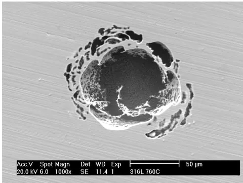
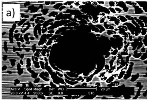
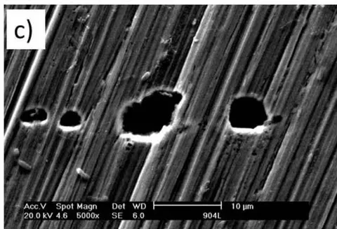
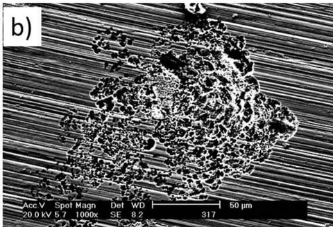
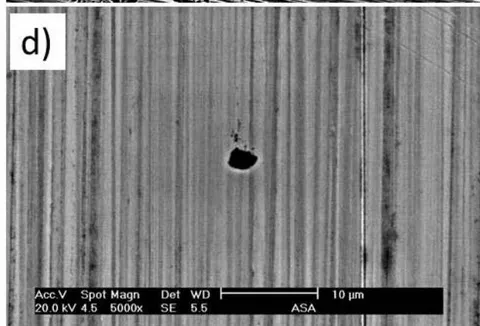
The 316L and 317L steels suffered pitting corrosion. For the 316L steel (Figure 9a), the pits possess a circular shape with a center hole. The pit propagates from the center to the edge and tries to grow with time. This effect is attributed to the chloride in the solution. The chloride ion is very small and can penetrate easily in sites of the 316L surface where the film is broken. The pits on the 316L steel grow but only in the center, as shown in Figure 9a. With the absence of in the solution, the environment is not so aggressive to permit the pits' growth. The 317L steel also suffered pitting corrosion, but its pits are so small compared with the ones of the 316L steel. The pits initiated, but they did not grow with time, as shown in Figure 9b. These pits are non-uniform. This result indicated that the 317L steel in some chloride-containing environments is also resistant, being also a good choice in some applications where the 316L cannot be used, for example, in the oil and gas industry in chloride-containing environments. The super austenitic stainless steels (904L and AL-6XN PLUSTM) presented pits much smaller than the ones found on the surface of conventional austenitic steels, as seen in Figure 9 (c-d). They are micro-pits, and after initiating, they passivate again before starting to grow. The effect of on the morphology of the pits for the 316L steel, the most affected steel in the experiments, is shown in Figure 10. In Figure 10a, one can see the pits for the potentiodynamic test using in the solution. In Figure 10b, it can be seen a single pit formed for the potentiostatic test with no in the solution. For the potentiostatic test (potential step), the pit did not grow as expected, leaving a hole in the center. All the micrographs of the alloys taken after the corrosion tests are in accordance by the graphs shown before. This experimental procedure has previously been used to qualify Ni-based alloys and hyper duplex stainless steel for raw seawater injection [14] and also used to study a Cr supermartensitic stainless steel related to localized corrosion [15]. These results combined with the linear polarization tests in -saturated aqueous solution, show that these materials (the super austenitic stainless steels) are an excellent option for chloride-containing environments with and without once they are cheaper than the Ni-based alloys. In some cases, the conventional 317L steel can also be a good option than the conventional 316L steel.
III. CONCLUSIONS
It can be concluded that the oil field formation water plays an important role as an aggressive substance in the pre-salt region. In chloride-containing environments, the 316L steel is not so resistant, and it is not recommended for the content of NaCl in the pre-salt region. The type of corrosion found was identified as pitting corrosion. For the 316L steel, pits were formed for both techniques used, but the pitting corrosion was more aggressive for the potentiodynamic technique due to in the solution and the absence of free oxygen. The 317L steel presented good pitting corrosion resistance when compared to the 316L steel. The two super austenitic stainless steels studied in this research (904L and AL-6XNPLUSTM) presented good pitting corrosion resistance. Both can be the solution for applications in chloride-containing environments as those found in the pre-salt region.
ACKNOWLEDGMENTS
The authors would like to thank to the Coordination for the Improvement of Higher Education Personnel (CAPES) and Cearense Foundation to Support Scientific and Technological Development (FUNCAP) for the financial support. A special thank is given to Wilman Italiano, who gave training in the electrochemical tests of potential step and also gave important contributions to this work.