1. Introduction
High-temperature dust removal, catalytic conversion, impact energy absorption—these scenarios place seemingly contradictory demands on materials: sufficient mechanical integrity to serve as a load-bearing body, yet three-dimensionally interconnected pore channels to allow fluid or energy to pass through. Over the past decades, engineers have mainly relied on two materials in this gap: porous metals and porous ceramics [1, 2]. The former, dominated by stainless steels and titanium alloys, exhibit good ductility, weldability, and insensitivity to thermal shock, but in oxidizing atmospheres above their surfaces are rapidly eroded and their creep resistance falls short [3]. The latter, honeycomb or foam ceramics represented by and cordierite, can push service temperatures above with excellent chemical stability, yet intrinsic brittleness remains a thorn—a single unexpected thermal shock can trigger catastrophic crack propagation [4]. These two systems occupy opposite ends of the performance spectrum, leaving a significant gap in between.
This gap provides an entry point for intermetallic compounds [5]. The chemical bonding in intermetallics is hybrid: metallic bonding contributes dislocation mobility, electrical and thermal conductivity, while covalent bonding raises the melting point, stiffness, and oxidation resistance. When iron and silicon, two extremely common elements, combine in a specific proportion, an phase with ordered structure is formed. Its yield strength anomalously rises rather than dropping near [6], and silicon atoms preferentially diffuse to the surface in oxidizing environments, spontaneously forming a continuous and dense passivation layer [7]. More practically, the interdiffusion rates of and at high temperature are highly asymmetric— diffuses into much faster than diffuses into . This mass-flow imbalance naturally generates a large number of vacancies during the phase transformation; upon coalescence, these vacancies leave three-dimensionally interconnected micropores [8]. In other words, framework construction and pore generation are accomplished in a single sintering step, without the need for additional pore-forming agents or polymeric template burnout. This mechanism is simple, controllable, and uses inexpensive raw materials, quickly attracting several research groups working on high-temperature filtration and catalyst supports [9].
From an application perspective, the most outstanding feature of porous materials is that they combine several usually incompatible attributes: decent mechanical strength (compressive strength typically in the range of ), acceptable thermal shock resistance, significantly better corrosion resistance than stainless steel in sulfur-containing flue gas or acidic condensate environments, and high-throughput permeability from the interconnected open-pore structure [10]. Their fracture toughness, although certainly inferior to pure metals, is still a notch above cordierite or ceramics, favoring progressive damage rather than sudden brittle fracture in service [11]. Collectively, these characteristics leave porous bodies with almost no direct competitor in oxidizing-corrosive environments at .
Looking back at the accumulation over the past two decades, the evolution of preparation technologies can be roughly divided into several lines. The earliest-trodden path was powder reactive sintering—mixing and powders, cold pressing, and vacuum sintering to complete compound synthesis and pore generation in one step [12]. This route requires low-end equipment and easily interfaces with existing powder metallurgy production lines, and remains the closest to mass production. Its limitation is that the randomness of particle stacking leads to a wide pore-size distribution, making it difficult to finely design pore morphology. To address this, researchers have introduced two distinct technical approaches. One is dealloying using amorphous ribbons as precursors: an alloy is melt-spun into an amorphous state, partially crystallized by heat treatment, and then the -rich phase is selectively dissolved in an acid solution, leaving a silicide skeleton with pores down to tens of nanometers and specific surface areas much higher than powder products [13]. The other route is more direct—sacrificial templating: organic sponges, particles, or carbon powders are blended into the powder compact, then burnt out or dissolved during sintering to form oriented or hierarchical pores in situ [14]. Since the mid-2010s, the maturation of additive manufacturing techniques such as laser powder bed fusion has begun driving the field from "making blocks" to "printing components," with complex-shaped parts possessing gradient porosity and intricate internal channels now directly formable from digital models [15].
In terms of literature trends, the development pace over the past twenty years falls roughly into three stages: before 2010, annual publications were scarce, with work concentrated in a few groups in Germany and Japan, focusing on basic sintering processes and phase characterization [16]; from 2010 to 2018, a steady growth phase saw research shift toward quantitative pore-structure-property correlations, with China's output markedly increasing [17]; since 2019, the growth rate has further accelerated, with additive manufacturing, nanoporous materials, and hierarchical pore design becoming high-frequency keywords [18]. This trajectory indicates that porous materials are advancing from "laboratory materials" toward "engineering candidate materials," though the overall technology readiness level is still climbing.
Problems are also evident. Some contradictions are inherited from other porous materials, e.g., once porosity exceeds about , compressive strength decays to levels unacceptable for engineering—the effective cross-sectional area of the load-bearing framework shrinks, and stress concentration is unavoidable [19]. Others are specific to the system: the thermal non-uniformity during powder reactive sintering is particularly pronounced when scaling up; small samples can achieve excellent homogeneity, but when scaling to pilot-scale components, the dispersion of microstructure and pore size across different regions becomes uncontrollable [20]. Furthermore, the vast majority of existing mechanical, corrosion-resistance, and permeability data were obtained under single-load or single-environment conditions. In real service, temperature, corrosive media, fluid impingement, and mechanical vibration often act simultaneously, and publicly available data on long-term behavior under such multi-factor coupling are extremely scarce [21]. Without such data, engineering design must rely on conservative safety factors, diluting the material's performance advantages.
This paper does not intend to be an exhaustive compendium. Over a thousand entries already exist in literature databases, and repeating them is meaningless. Instead, I aim to extract a coherent logic from published results: how did this material evolve from a block of sintered alloy to one whose pore structure can be tailored for specific applications? What choices were right, and which joints remain unconnected? The subsequent sections are organized as follows: Section 2 dissects the principle differences and process boundaries of four mainstream pore-forming methods; Section 3 discusses structure-property relationships among microstructure, phase constitution, and mechanical, thermal, and permeation properties; Section 4 consolidates several embryonic engineering applications such as high-temperature filtration, damping dissipation, thermal management, and surface protection; Section 5 summarizes the key scientific and technological bottlenecks hindering industrialization; Section 6 provides directional outlooks from perspectives of multi-scale structural design, multi-component composite, and data-driven process development.
2. Main preparation methods and optimization of Fe-Si porous materials
Turning iron and silicon into a porous body essentially accomplishes one thing: while consolidating into a shape, a portion of space is "emptied." But it is precisely the mechanism of this "emptying" that fundamentally distinguishes different technical routes. Currently, four relatively systematic pore-forming approaches exist: reactive sintering relies on vacancies generated by differential atomic diffusion rates; dealloying depends on the huge disparity in electrochemical stability between two phases; sacrificial templating uses a placeholder-removal logic for anti-structure design; and additive manufacturing directly treats pores as part of the printing path. These four sets of logic correspond to four completely different process philosophies, and their respective applicability boundaries are thus defined.
2.1. Powder reactive sintering
Reactive sintering is the most classical and industrially-ready route for porous materials. Its core principle exploits a quite unique intrinsic feature of the system: the diffusion rate of in is much higher than that of in . When and powders are mixed, cold-pressed, and heated in vacuum to about , atoms preferentially migrate into the interior of particles. This asymmetric mass flow disrupts the local material balance, and a large number of vacancies are injected into the diffusion front. When the vacancy concentration becomes supersaturated, they nucleate, grow, and coalesce, leaving pores near the original particle locations. Meanwhile, and react to form a series of intermetallic compounds—typically the phase appears first, then progressively transforms into as continues to diffuse, ultimately yielding a framework dominated by the ordered structure. Pore formation and phase formation are two manifestations of the same process, requiring no external pore-forming agent [8, 12].
This route has long held mainstream status because of its process simplicity. Pretreatment of and powders, mixing, cold pressing, and vacuum sintering—the entire flow is highly compatible with conventional powder metallurgy lines, with low equipment barriers and controllable raw material costs. By adjusting three core parameters—silicon content, powder particle size, and sintering schedule—the final porosity and pore-size distribution can be regulated within a certain range. Table 1 summarizes typical process windows and the corresponding pore-structure characteristics.
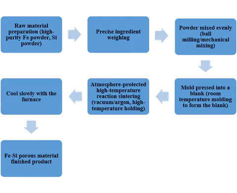
Table 1: Typical process parameters and pore-structure characteristics of reactive-sintered Fe-Si porous materials [12, 20].
| Process parameter | Typical range | Main influence on pore structure |
|---|---|---|
| content | Total porosity increases with content, but excess unreacted may block channels | |
| powder size | Larger size increases average pore size but broadens distribution | |
| powder size | Fine promotes uniform diffusion; coarse causes localized macropores and residual | |
| Compaction pressure | Higher pressure raises green density, reducing post-sintering porosity | |
| Sintering temperature | Higher temperature accelerates diffusion and vacancy coalescence; pore size increases, porosity first rises then falls | |
| Heating rate | Slow heating favors reaction homogenization; too fast may produce delamination cracks | |
| Holding time | Longer time promotes phase homogenization, but excessive time leads to pore coarsening and shrinkage |
Table 2: Typical mechanical and permeation properties of reactive-sintered Fe-Si porous materials [10, 12, 51, 71].
| Property | Typical range | Test condition / Note |
|---|---|---|
| Porosity | Archimedes drainage method | |
| Average pore size | Bubble point or mercury intrusion | |
| Compressive strength | Room temperature, lower end at porosity | |
| Flexural strength | Three-point bending, span | |
| Darcy permeability () | Room-temperature air, nearly linear with porosity | |
| Thermal shock critical | Water quenching, strength loss as criterion | |
| CTE | , close to stainless steels |
Typical porosity ranges from to , average pore size from a few microns to thirty-forty microns, and compressive strength can reach —sufficient to meet the mechanical requirements of most filter supports. Specific performance data vary with process conditions; Table 2 lists representative ranges reported in the literature.
However, the "spontaneity" of pore generation, while offering simplicity, also imposes unavoidable process boundaries. Since pore morphology is entirely determined by the particle packing state and the vacancy coalescence driven by diffusion, any factor affecting powder mixing uniformity and local thermal field is faithfully recorded in the pore structure. Batch-to-batch fluctuations in powder size, spatial differences in green compact density, and temperature non-uniformity within the sintering furnace—all controllable on small laboratory samples—can, once scaled to tubular or plate-shaped components with outer diameters exceeding , cause obvious radial gradients in pore size and phase distribution. Another more fundamental limitation lies in the designability of the pore structure: pore morphology produced by reactive sintering is restricted by diffusion paths and particle geometry, making it difficult to escape the fixed paradigm of "quasi-spherical open pores with wide distribution." When porosity exceeds about , the effective load-bearing area of the framework drops sharply, and strength decays faster than a power-law relation, causing the mechanical reliability of high-porosity products to plummet.
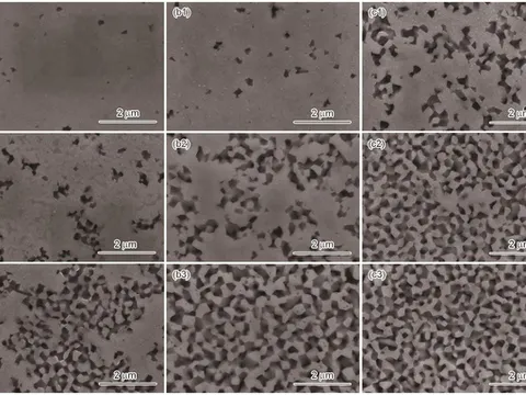
Table 3: Structural comparison of Fe-Si porous bodies from dealloying and reactive sintering [13, 22, 23, 24, 25].
| Feature | Reactive sintering | Dealloying |
|---|---|---|
| Typical pore size range | ||
| Specific surface area | ||
| Ligament/wall size | ||
| Pore morphology | Quasi-spherical open pores, broad distribution | Worm-like/network connected pores, narrow distribution |
| Product form | Blocks, tubes, plates | Films, ribbons, powders |
| Skeleton phase | Mainly , minor | -rich amorphous + nanocrystals |
2.2. Dealloying method
If reactive sintering "burns out pores," dealloying follows the opposite strategy—first cast a dense multi-phase precursor, then chemically corrode away one phase selectively, leaving a porous skeleton. In the system, this idea usually starts with melt-spinning to produce amorphous ribbons. Because the glass-forming ability of pure binary is limited, small amounts of or are often added to enhance amorphous stability. The amorphous precursor is partially crystallized by controlled annealing, forming solid-solution grains dispersed in a residual amorphous matrix; subsequent acid treatment (e.g., dilute or ) selectively dissolves the phase, while the -rich phase—containing or similar intermetallics—is retained, forming a skeleton with three-dimensionally interconnected nanopores [13, 22, 23].
The most attractive feature of dealloying is that it can break through the lower pore-size ceiling of reactive sintering. Reactive-sintered pores rarely go below the micron level, whereas dealloying can stably produce porous bodies with average pore sizes in the range and specific surface areas exceeding —attributes highly valued in catalysis, sensing, and supercapacitor electrodes. Ligament size and pore size can be jointly tuned via precursor composition and annealing schedule, providing fairly high structural reproducibility under the logic of densification-followed-by-corrosion. Table 3 compares the key structural features of dealloying and reactive sintering methods.
However, the process boundaries of this route are equally sharp. First is the natural limitation in forming dimensions—melt-spinning yields ribbons only tens of micrometers thick, and chemical corrosion can hardly penetrate deep into a bulk body without breaking ligament continuity, thus dealloying ties itself from the outset to products in the form of films or powders. Efficient low-damage integration technologies to assemble these nanoporous ribbons into macroscopic components are still lacking. Secondly, the corrosion process itself is a precise balance between time and structural integrity: insufficient corrosion leaves un-interconnected pores, while over-corrosion thins ligaments and causes brittle framework collapse. Residual or impurities are difficult to wash out thoroughly, and systematic data on whether they accelerate framework degradation under high-temperature oxidation are absent. Cost is also a practical issue—from amorphous ribbon fabrication to fine corrosion control, the efficiency and batch capacity of the entire chain still lag behind reactive sintering by orders of magnitude.
2.3. Templating method
Although reactive sintering and dealloying differ in principle, they share a common point: the final pore structure is the result of "spontaneous" evolution within the material, with the human role mainly setting boundary conditions. Sacrificial templating, by contrast, reclaims design authority—placeholders are pre-embedded in the powder compact, and after the compact builds adequate framework strength, the placeholders are removed by pyrolysis, dissolution, or vaporization, leaving cavities that are nearly faithful reverse replicas [14, 31, 32, 33, 34, 35, 36, 37, 38, 39, 40].
The material and geometry of the template directly determine the macro-configuration of the pores. Different templates vary significantly in applicable pore size, porosity, and removal method; Table 4 lists key parameters of several mainstream template systems. The greatest advantage of templating is that it decouples porosity and pore size from the kinetics of sintering densification, so that high porosity no longer inevitably means strength collapse—as long as the skeleton undergoes reasonable secondary sintering densification after template removal, the pore walls themselves can be made sufficiently strong.
Table 4: Common placeholder systems used in templating and their process characteristics [14, 31, 32, 33, 34, 35, 36, 37, 38].
| Template type | Pore size range | Achievable porosity | Removal method | Advantages | Limitations |
|---|---|---|---|---|---|
| PU sponge | Pyrolysis, | Open-cell network, high porosity | Cracking during removal, carbon residue | ||
| particles | Water washing, | Controllable pore size, mild removal | Slow de-salting, residue risk | ||
| Carbon powder | Oxidation burnout, | Also acts as reactant to generate pores | Requires oxidative atmosphere, local overheating | ||
| Starch/cellulose | Pyrolysis, | Green, cheap raw materials | Off-gas emission, high carbon residue | ||
| Ice crystals (freeze-casting) | (section) | Freeze-drying | Oriented lamellar pores, biocompatible | Narrow process window, low strength |
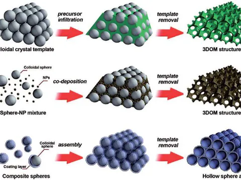
Nonetheless, the placeholder-removal logic introduces a new set of operational complications. One arises from the template-removal process: if organic templates are heated too rapidly during pyrolysis, the escape of decomposition gases creates internal pressure, causing wall cracking or even macroscopic part fracture. templates require water-washing removal, and if the skeletal pre-sintering is insufficient, water washing can cause local collapse. Another complication is residue contamination: incomplete carbonization of organic foams leaves behind thin glassy carbon layers; impurity cations in salt may enter the matrix at high temperature and degrade corrosion resistance. Moreover, although templating can precisely control the macroscopic geometry of pores, its ability to tune microscopic surface morphology is limited—the internal surfaces of pore walls are usually relatively smooth, with specific surface areas far lower than dealloyed products. These boundaries make templating particularly suitable for scenarios where flow pressure drop and volume filtration are the primary design goals (e.g., high-temperature gas filtration), but inadequate where nanoscale surface activity is required.
2.4. Additive manufacturing method
Additive manufacturing entered the field of porous intermetallics most recently, yet it brings a fundamental paradigm shift in manufacturing. The three foregoing methods, whether by diffusion, corrosion, or placeholders, all produce a homogeneous or statistically homogeneous porous body; additive manufacturing—especially laser powder bed fusion (LPBF)—allows engineers to actively define, with a resolution on the order of a hundred micrometers, where solid, where cavity, and where gradient transition layers exist in three-dimensional space [15, 41, 42, 43, 44, 45, 46, 47, 48, 49, 50].
The pore-generating mechanism of additive manufacturing can be roughly split into two levels. At the macroscopic level it is topology design: CAD models construct lattice structures (e.g., body-centered cubic, diamond, triply periodic minimal surfaces), and the laser melts the powder layer by layer along the defined path, faithfully reproducing the designed cross-section from a digital model into physical reality. At the microscopic level, the process parameters themselves can also become pore-forming tools: under reduced laser power or increased scan speed, gaps of insufficient fusion and local un-melted powder zones appear between melt tracks; these powder-scale pores superimpose on the macroscopic lattice pores, creating a hierarchical pore structure. For the system, pre-alloyed powders or elemental powder blends are typically used for full-melting printing; the sphericity and flowability of the powder have a significant impact on forming quality. Table 5 lists typical process windows and key influencing factors for LPBF-formed porous bodies.
Table 5: Key process parameters and influences for LPBF-formed Fe-Si porous bodies [41, 42, 43, 44, 45, 46].
| Parameter | Typical range | Influence on forming quality |
|---|---|---|
| Laser power | Too low poor fusion, weak interlayer bonding; too high burning, element evaporation | |
| Scan speed | Too fast increased un-melted porosity; too slow oversized melt pool, reduced resolution | |
| Hatch spacing | Too large insufficient melt-track overlap, forming interconnected gaps; too small excessive densification | |
| Layer thickness | Larger thickness higher build rate, but insufficient penetration causes weak interlayer bonding | |
| Preheating temperature | Higher preheating reduces thermal stress and cracking, but increases oxidation risk | |
| Powder sphericity | (Hausner ratio) | Poor flowability causes uneven powder spreading, local density fluctuations |
| Powder size (D50) | Fine powder improves surface quality but flowability; coarse powder opposite |
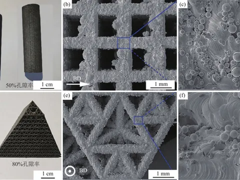
Additive manufacturing has opened two entirely new doors for this field. The first door is gradient porosity design: a single component can simultaneously have dense load-bearing regions, large-pore low-flow-resistance regions, and fine-pore high-surface-area regions, with smooth transitions among them—something previously achievable only by multi-piece bonding or mechanical assembly. The second door is the integrated forming of complex internal channel networks: for catalytic reactors, compact heat exchangers, and other components requiring internal network-like flow channels, LPBF has become almost the only feasible manufacturing solution.
The price is naturally steep. Cost is the most immediate barrier—whether the specialized powder feedstock for intermetallics or the hourly depreciation of LPBF equipment and inert gas consumption, all dictate that it is temporarily suited only for high-value-added, small-batch, or custom applications. Technical boundaries run deeper: exhibits severe intrinsic brittleness at room temperature, and the steep thermal gradients and repeated thermal cycling during printing can easily induce micro-cracks. Even with optimized parameters, crack density can only be reduced to a certain critical level but rarely eliminated entirely. Furthermore, the laser spot size (usually ) and powder layer thickness () jointly define a lower resolution limit, which means sub-micron or nanoscale pores cannot be obtained by direct printing but must rely on post-treatment or coupling with dealloying. Surface roughness is also a weakness of additively manufactured porous parts—un-melted powder particles adhering to pore walls both increase flow resistance and can become crack initiation sites under fatigue loading.
2.5. Method comparison and process selection criteria
Viewing the four methods together, two common threads run through them. The first thread is the control precision of pore size and specific surface area: from the wide-distribution micron pores of reactive sintering, to the definable macropores of sacrificial templating, to the precisely controlled nanopores of dealloying, and finally to the cross-scale design of additive manufacturing—designability increases stepwise, but so does cost almost proportionally. The second thread is the shift from "self-organization" to "imposed organization": reactive sintering and dealloying rely heavily on the material's own physicochemical properties to generate pores, with process control indirect and statistical; sacrificial templating and additive manufacturing treat pores as geometric information written proactively, with the process reaching into the specific position and shape of each pore.
These two threads, combined with real industrial constraints, form a rough but effective selection framework. Table 6 provides a comprehensive multi-dimensional comparison of the four methods, which can serve as a preliminary reference for process selection [9, 12, 13, 14, 15].
Table 6: Comprehensive comparison of the four pore-forming methods [9, 12, 13, 14, 15].
| Comparison dimension | Reactive sintering | Dealloying | Sacrificial templating | Additive manufacturing |
|---|---|---|---|---|
| Pore size range | (macropores) | |||
| Specific surface area | ||||
| Porosity range | (design value) | |||
| Designability of pores | Low | Medium | High | Very high |
| Maximum product size | (thickness) ② | scale ③ | ||
| Process maturity | High (near-industrial) | Low (lab) | Medium (pilot) | Low (lab-to-pilot) |
| Relative cost | Low | High | Medium | Very high |
| Difficulty for hierarchical pores | Difficult | Difficult | Medium | Easy (by design) |
| Suitable application | High-temperature filter supports | Catalysis/electrodes/sensing | Graded filtration/bio-implants | Gradient channels/lightweight components |
| Key limitation | Wide pore distribution, scaling homogeneity | Film-only form, residue control | Template-removal defects, inert pore-wall surface | Crack sensitivity, high cost, resolution limit |
At the same time, it should be recognized that these four routes are not mutually exclusive. Some of the most interesting recent progress occurs precisely at their intersections: using additive manufacturing to print a precursor containing templates, then removing the template to create hierarchical pores; fabricating a macroporous support by reactive sintering and then generating a nanoporous layer on the pore walls by dealloying; or introducing partial reactive sintering into a sacrificial templating route to improve wall densification. These hybrid strategies demonstrate that the so-called "boundaries" of the four methods are not theoretical endpoints but contour lines drawn by current process capabilities. The structure-property relationships discussed in the next chapter are exactly what different pore structures and phase constitutions determine within these contour lines.
3. Microstructure and properties: Mechanical-functional coupling across multi-scale structures
If Chapter 2 addressed "how to make it," this chapter confronts "what is the thing made like" and "why is it like this." The complexity of porous materials lies in the fact that their macroscopic behavior is never a monotonic function of a single parameter—porosity, pore-size distribution, pore morphology, ligament cross-section, grain size, phase constitution, degree of order, defect distribution—these elements intertwine to jointly determine mechanical load-bearing capacity, fluid transport efficiency, and environmental tolerance. Decomposing these coupling relationships is both the epistemological core for understanding porous materials and the methodological basis for guiding process optimization.
3.1. Pore-structure parameter system and characterization methods
Before entering the discussion of properties, it is necessary to establish a clear parameter language. The pore structure of a porous body is not a vague "porous state" but is defined by several independent yet interrelated geometric parameters. The most fundamental level consists of three scalar parameters: porosity, average pore size, and specific surface area. Porosity defines "how much void," average pore size answers "how large the voids are," and specific surface area answers "how much interface exists." There is no simple functional relationship among the three—two materials with the same porosity can be composed of a few large pores or a multitude of small pores, and their average pore size and specific surface area can differ by more than two orders of magnitude.
The second level is distribution parameters. The pore-size distribution curve—whether obtained by mercury intrusion porosimetry, bubble-point method, or gas adsorption-desorption isotherms—carries far more structural information than the average pore size. A narrow, sharp distribution implies structural homogeneity, with the responses of various locations to fluid or stress tending to synchronize; a broad, multi-modal distribution hints at heterogeneity, with possible preferential flow channels or stress concentration zones. For filtration applications, the upper tail of the pore-size distribution is often more critical than the average value—the largest of pores determine the lower limit of interception precision. Similarly, pore morphology must be quantified: pore shape factors (e.g., roundness, aspect ratio), open porosity (the fraction of interconnected pores in total pore volume), pore connectivity (described by coordination number—the average number of neighboring pores connected to a given pore), and pore orientation distribution (isotropic versus layered directional arrangement).
The third level is the microstructural parameters of the ligament/pore wall. The porous skeleton is not merely "the walls between pores"; it is itself a microstructural entity. Ligament cross-section size, the grain morphology inside the ligament (equiaxed or columnar), phase constitution and degree of order, grain-boundary and phase-boundary characteristics, and the distribution of micro-cracks and micro-pores—these second-tier structural features determine the intrinsic mechanical response and chemical stability of the skeleton itself. For the system, whether the ligament interior is a single-phase ordered solid solution or mixed with second phase, whether the grain size is nanometer or micrometer scale, and whether silicon oxides or borides segregate at grain boundaries, all leave clear fingerprints on macroscopic properties.
This three-level parameter system—macroscopic pore geometry, mesoscopic pore morphology, and microscopic skeleton organization—together constitutes the bridge connecting processing and performance. Any single performance index is rarely determined by a single parameter; the interplay and trade-offs among parameters are the core difficulty in porous material design.
3.2. Mechanical behavior: From uniaxial compression to service reliability
Mechanical performance is the first hurdle for porous intermetallics moving from laboratory to engineering application. Compared with dense metals, the mechanical response of porous bodies exhibits three notable characteristics: severe strength attenuation, nonlinear elastic modulus, and brittle fracture tendency. All three are closely related to pore structure, but in different ways.
3.2.1. Strength-porosity relationship and its deviation
That the strength of porous materials decreases with increasing porosity is expected. The real engineering question is: how fast does it drop, and does it follow a predictable law?
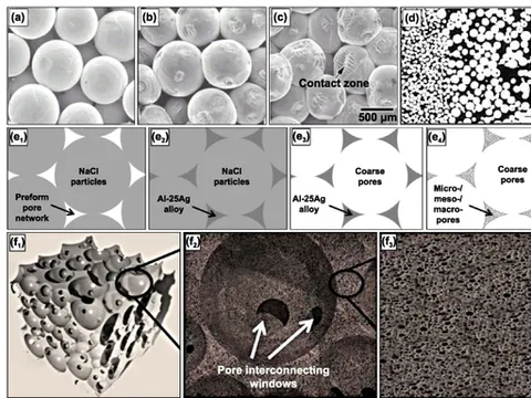
The classical Gibson-Ashby model provides a concise power-law framework: for open-cell foams, yield strength scales with relative density to the power ; for closed-cell foams, the exponent lies between and . A large body of experimental data shows that reactive-sintered porous materials roughly follow this trend—when porosity increases from to , compressive strength decreases from about to about , with a fitted exponent between and [1, 51]. This seemingly well-behaved decay curve, however, exhibits a clear inflection when porosity exceeds about : strength drops abruptly, with actual values systematically lower than Gibson-Ashby predictions. This implies that in the high-porosity region, some additional weakening mechanism is activated.
Researchers gradually realized that the root of this deviation lies in the geometric percolation transition of pores from "isolated" to "connective." In the low-porosity regime, pores approximate spherical defects dispersed in a continuous matrix, the stress concentration effect of each pore is relatively independent, and equivalent-medium models can reasonably describe it. When porosity exceeds a critical value (about for the system), pores begin to interconnect over large distances, ligaments transform from "thick walls" into "slender columns," and the loading mode shifts from predominantly compressive body stress to framework deformation involving significant bending components. At this point, the weakest ligaments—exactly those located at the upper tail of the pore-size distribution with the smallest cross-sectional area—become the "mechanical fuse points" of the entire skeleton. The overall strength is no longer determined by the average ligament size but by the extreme-value statistical distribution of the weakest links. This is a physical picture that the homogenization framework of Gibson-Ashby cannot capture.
Table 7: Behavior differences across porosity ranges.
| Porosity range | Strength change | Fitted exponent | Attenuation feature | Failure mechanism | Model applicability |
|---|---|---|---|---|---|
| Gentle, fits prediction | Isolated pores, compression, equivalent medium | Good | |||
| (beyond percolation threshold) | Sharp drop, below prediction | Deviates from power law | Accelerated, "mechanical fuse" | Interconnected pores, bending, weakest ligament dominated | Poor |
3.2.2. Nonlinear decrease of elastic modulus
The attenuation of elastic modulus with porosity is more severe than that of strength—a general rule for porous bodies. To understand this, one must distinguish two different measurement concepts: the engineering elastic modulus is the secant slope of the stress-strain curve in the low-strain segment, but for porous bodies containing micro-cracks, the curve may not be strictly linear even within a strain range. Micro-cracks already close or open under very small loads, causing loading-unloading paths to not coincide and the modulus to vary with the number of loading cycles.
For porous materials, the elastic modulus is usually assessed by ultrasonic measurement of longitudinal wave velocity, to avoid pseudo-nonlinearity from micro-crack closure during mechanical loading. Sonic-measured modulus data indicate that as porosity increases from to , the dynamic elastic modulus drops rapidly from about for dense to —a decrease () far greater than the corresponding strength decrease () [63]. This accords with the general intuition in solid mechanics: pores not only reduce the load-bearing area but also significantly reduce structural stiffness, but the degree of stiffness loss depends on pore shape—flattened pores along the loading direction drastically reduce stiffness, while transversely elongated pores do the opposite. This also explains why the equiaxed pores produced by sacrificial templating generally provide a higher elastic modulus at the same porosity than the irregular pores from reactive sintering.
Table 8: Comparison of elastic modulus and strength attenuation in Fe-Si porous materials.
| Comparison dimension | Elastic modulus | Compressive strength |
|---|---|---|
| Attenuation rate with porosity | More severe | Relatively gentler |
| Decrease from porosity | ||
| Typical value change | Dense | - |
| Measurement method | Ultrasonic dynamic modulus, avoids micro-crack closure pseudo-nonlinearity | Conventional compression |
| Pore-shape sensitivity | Equiaxed pores give higher modulus; flattened pores normal to load cause greatest reduction | - |
3.2.3. Fracture toughness and inherent brittleness
If strength and elastic modulus still leave acceptable engineering margins for porous bodies, fracture toughness is an inherently deficient indicator. At room temperature, dense is itself a brittle intermetallic, with a bulk fracture toughness typically only [57]. The introduction of pores only makes matters worse.
The fracture behavior of porous bodies must consider brittleness superposition at two scales. At the macroscopic scale, pores are stress concentrators and crack nuclei. For open-cell structures, ligament cross-sections experience significant bending stresses, and the extremely low fracture work of means that a ligament will undergo cleavage fracture after very little plastic deformation. Once a ligament breaks, the load redistributes to adjacent ligaments, causing a chain-reaction collapse—macroscopically exhibiting a completely brittle failure mode, with the stress-strain curve dropping vertically to zero after the peak. At the microscopic scale, cleavage planes in grains (the families of the ordered structure are low-index cleavage planes) provide obstacle-free paths for crack extension. When grains are pinned by silicon oxides or boride precipitates, the crack may be forced to deflect, but the energy consumed by deflection is extremely limited and far from producing a macroscopic toughening effect [11, 53].
This dual-scale brittleness means that the mechanical design of porous materials cannot follow the plastic energy-absorption logic of metallic porous materials. Its failure gives almost no warning, with the transition from "intact" to "shattered" extremely abrupt under critical load. Therefore, conservative allowable-stress design criteria should be adopted for load-bearing porous components, supplemented by nondestructive testing methods (such as acoustic emission monitoring) to capture early signals of micro-crack propagation [58].
Table 9: Fracture toughness characteristics and brittle failure mechanisms of Fe-Si porous materials.
| Feature dimension | Description |
|---|---|
| Dense body | (room temperature, intrinsically brittle) |
| Effect of porosity | Further deterioration after introducing pores, no toughening possible |
| Macroscopic fracture mechanism | Pores act as stress concentrators and crack nuclei; ligaments under bending stress, cleavage fracture triggers chain collapse; stress-strain curve drops vertically post-peak |
| Microscopic fracture mechanism | planes of structure serve as low-index cleavage planes; cracks propagate unhindered; precipitate pinning only causes limited deflection, negligible toughening effect |
| Failure mode | Dual-scale brittleness superimposition; completely brittle failure, no warning, extremely abrupt from intact to shattered |
| Design criteria | Cannot use plastic energy-absorption logic; adopt conservative allowable-stress method, supplemented by acoustic emission monitoring for early damage detection |
3.2.4. Behavior under thermal stress fields
In high-temperature service environments—exactly the most anticipated application scenario for porous materials—thermal stress becomes an unavoidable issue. A filter tube undergoes temperature changes of tens to hundreds of degrees during start-up and shut-down; due to the lag in heat conduction inside the skeleton, spatial gradients arise, and gradients mean thermal stress.
The system possesses two thermodynamically advantageous characteristics: one, its coefficient of thermal expansion (CTE) is , close to common stainless steels, reducing thermal mismatch stress with metallic support structures [64]; two, maintains the ordered structure from room temperature to about , with no solid-state phase transformation, hence no additional stress from phase-change volume effects. However, the porous structure itself amplifies the damaging potential of thermal stress. The stress concentration factor around pores increases with the sharpness of the pore morphology; the long-axis tips of irregular pores may experience stresses several times the macroscopic average. Repeated thermal cycling leads to thermal fatigue—micro-cracks initiate from these stress-concentration sites, slowly propagate, until some critical ligaments lose their load-bearing capacity.
Thermal shock experiments—rapidly plunging a sample taken from a furnace into cold water—simulate an extreme condition. For reactive-sintered porous bodies, when the thermal shock temperature difference is about , strength retention can exceed ; when exceeds , penetrating cracking usually occurs [62]. The key material parameters influencing thermal shock resistance are the combination of thermal conductivity, elastic modulus, fracture strength, and CTE—ideally high thermal conductivity (reducing gradients), low modulus and high strength (withstanding larger strain without fracture), and low CTE (reducing strain amplitude). Unfortunately, for a given chemical system, trade-offs often exist among these parameters; therefore, improving thermal shock resistance requires multi-parameter synergistic optimization rather than conventional single-variable adjustment.
Table 10: High-temperature thermal stress characteristics and thermal shock resistance of Fe-Si porous materials.
| Aspect | Description |
|---|---|
| High-temperature application scenario | Filter tubes and other components experience temperature changes of tens to hundreds of degrees during start-up/shutdown |
| Thermal stress source | Lag in heat conduction creates spatial temperature gradients inside the skeleton, generating thermal stress |
| Advantageous feature—CTE | , close to stainless steel, reducing thermal mismatch stress with supports |
| Advantageous feature—structural stability | maintains order from to , no solid-state transformation, no additional phase-change volume stress |
| Detrimental feature—stress concentration | Porous structure amplifies thermal stress; stress concentration factor around pores increases with sharpness; stress at long-axis tips of irregular pores can be several times average |
| Detrimental feature—thermal fatigue | Repeated cycling causes micro-crack initiation at stress-concentration sites and slow propagation, leading to ligament loss |
| Thermal shock test method | Sample taken from furnace, rapidly quenched in cold water, simulating extreme conditions |
| Thermal shock performance—moderate | , strength retention |
| Thermal shock performance—high | , penetrating cracks usually occur |
| Key parameters for thermal shock resistance | Combination of thermal conductivity (high), elastic modulus (low), fracture strength (high), CTE (low) |
| Parameter trade-offs | For a given chemical system, parameters often trade off; improving thermal shock resistance requires multi-parameter synergistic optimization |
3.3. Fluid transport performance: Permeability and filtration characteristics
In the vast majority of applications, porous materials need to interact with fluids—gaseous or liquid media flowing through pore channels, either being filtered, distributed, or participating in mass transfer and reaction. The essence of fluid transport performance is how fast the porous body allows media to pass under a given driving force; filtration performance concerns what particle size it can intercept and at what pressure drop cost.
3.3.1. Darcy permeability and its deviation
At sufficiently low flow velocities, flow in porous media obeys Darcy's law: volumetric flow rate is proportional to the pressure-drop gradient, with the proportionality factor being permeability divided by fluid viscosity . Permeability is an inherent geometric property of the porous body, independent of fluid type (provided no chemical reaction occurs between fluid and skeleton). In the Darcy flow regime, permeability is jointly determined by porosity , pore size , and tortuosity ; the classic Kozeny-Carman relation writes , where is specific surface area [71]. The core message of this relation is that permeability is extremely sensitive to porosity—a increase in porosity can multiply permeability several times; at the same porosity, structures with coarser average pore size and lower specific surface area have higher permeability.
Experimentally measured permeability of reactive-sintered porous bodies typically falls in the range to , comparable to porous stainless-steel filter media, but lower than the typical levels of honeycomb ceramics [71, 72]. This is related to the relatively low porosity (usually not exceeding ) and the wide pore-size distribution of porous bodies—the fine-pore tail significantly raises specific surface area, thereby compressing permeability.
When the flow velocity increases and the Reynolds number exceeds the laminar critical value, inertial effects become noticeable, and Darcy's law must be supplemented by a Forchheimer correction term: , where is the inertial resistance coefficient and is fluid density. For gaseous media, this non-Darcy regime is often non-negligible—high-temperature gases have increased viscosity and decreased density, so the superficial velocity (mass flux converted) can easily enter the inertia-dominated range. This means that when designing high-temperature gas filtration systems, selecting membranes based solely on Darcy permeability is insufficient; the additional pressure drop contributed by the inertial term must be accounted for, to avoid the actual operating point deviating from design expectations [73].
Table 11: Permeability and flow characteristics of Fe-Si porous materials.
| Aspect | Description |
|---|---|
| Darcy flow behavior | At low velocity, volumetric flow rate is proportional to pressure-drop gradient, governed by ; depends only on porous body geometry, independent of fluid type |
| Geometric determinants of permeability | Determined by porosity , pore size , tortuosity ; classical Kozeny-Carman: , is specific surface area |
| High sensitivity to porosity | increase in porosity can multiply permeability several times; at same porosity, coarser pore size and lower specific surface area yield higher |
| Measured permeability range | , same order as powder-sintered stainless steel filters, but significantly lower than honeycomb ceramics |
| Reasons for relatively low permeability | Porosity usually ; fine-pore tail in broad distribution significantly raises specific surface area, compressing |
| Non-Darcy flow regime (high velocity) | When exceeds laminar critical value, Forchheimer correction applied: , is inertial coefficient |
| Non-Darcy effect in hot gases | High-temperature gases have higher viscosity, lower density; superficial velocity easily enters inertial-dominated regime; non-Darcy term non-negligible |
| Engineering selection note | Design of hot-gas filtration systems must include additional pressure drop from inertial term; relying only on Darcy permeability may cause actual pressure drop to significantly exceed design expectation |
3.3.2. Trade-off between filtration efficiency and pressure drop
Filtration is one of the oldest and most widespread functions of porous materials. For depth filtration—where particles are captured inside pore channels rather than accumulating on the surface—filtration efficiency depends on two mechanisms: size sieving and inertial impaction/diffusive capture. Size sieving directly intercepts particles larger than the pore-throat size, a hard threshold determined by the upper tail of the pore-size distribution. Inertial impaction and diffusive capture act on sub-micron and nano-particles, respectively, and are jointly regulated by flow velocity and pore size.
A practical advantage of porous bodies is the natural chemical activity of their skeleton surfaces— atoms in form a thin iron-oxide layer under high-temperature oxidizing atmospheres, which has a certain chemisorption capacity for some gas-phase components and fine particles, thus providing an auxiliary capture mechanism beyond pure physical interception [72, 76]. For sulfur- or chlorine-containing high-temperature gases—such as coal-gasification syngas—whether the skeleton undergoes excessive sulfidation or chlorination directly affects the long-term stability of filtration efficiency. Preliminary laboratory data indicate that under conditions of concentration below several hundred ppm and temperature , the sulfide layer formed on the surface has controllable thickness, and permeability and filtration efficiency do not significantly degrade in the short term [81, 82]. However, long-term exposure data exceeding hundreds of hours are still very scarce—a critical knowledge gap impeding the entry of porous materials into coal-chemical and biomass-gasification sectors.
Filtration design and permeability are always in conflict. Pursuing higher filtration precision—i.e., intercepting smaller particles—requires reducing pore size, especially trimming the upper tail of the pore-size distribution. But reducing pore size inevitably lowers permeability, meaning that at the same flux, a larger filtration area or higher driving pressure difference is needed. A high driving pressure difference not only increases energy consumption but also imposes greater fluid-drag force on the weak pore walls, potentially triggering micro-crack propagation and filtration-precision degradation over long-term operation. This conflict is amplified in the system by its inherent brittleness—operators dare not apply overly high pressure difference to avoid framework fracture, yet permeability is insufficient to deliver the required flux at low pressure difference. An industrial compromise is to use an asymmetric membrane structure: a fine-pore -based membrane is coated (by dip-coating or spraying) onto a macroporous support produced by reactive sintering; the support provides mechanical strength and low flow resistance, while the membrane layer provides filtration precision [111, 112]. The success of this scheme depends on the membrane-support bonding strength and interfacial stability during long-term service, which is also one of the currently active research directions.
Table 12: Filtration characteristics, advantages, and engineering conflicts of Fe-Si porous materials.
| Aspect | Description |
|---|---|
| Depth filtration mechanisms | Size sieving: Particles larger than pore throats directly intercepted, governed by upper tail of pore-size distribution; inertial impaction/diffusion: acts on sub-micron and nano-particles, jointly regulated by velocity and pore size |
| Skeleton chemical activity | forms iron-oxide thin layer on surface under high-temperature oxidizing atmosphere, providing chemisorption capability for some gas-phase species and fine particles, supplementary capture mechanism beyond pure physical interception |
| Stability in sulfur/chlorine-containing hot atmospheres | At , , sulfide layer thickness controllable in short term, insignificant effect on permeability and filtration efficiency; long-term () exposure data very scarce, key knowledge gap for coal-chemical and biomass gasification |
| Filtration precision—permeability conflict | Improving precision requires reducing pore size and trimming upper tail, lowering permeability; same flux needs larger area or higher pressure drop; high pressure drop raises energy consumption and may induce micro-crack propagation |
| Brittleness amplification effect | Inherent brittleness of exacerbates the conflict: cannot withstand very high pressure drop to avoid fracture; yet permeability insufficient to provide required flux at low pressure drop |
| Industrial compromise | Asymmetric membrane structure: macroporous reactive-sintered support + coated fine-pore membrane; support provides strength and low flow resistance, membrane provides precision; membrane-support bonding and long-term interfacial stability are critical and actively researched |
3.4. Thermophysical properties: Heat transfer behavior from steady-state to transient
As materials intended for high-temperature applications, the thermophysical properties of porous bodies not only determine their own service behavior but also indirectly affect structural reliability via thermal-mechanical coupling paths. The two core parameters are thermal conductivity and coefficient of thermal expansion—they control the establishment of steady-state temperature fields and the magnitude of thermal stress, respectively.
3.4.1. Structural sensitivity of effective thermal conductivity
The effective thermal conductivity of a porous body is a function of the skeleton-phase thermal conductivity, pore-phase thermal conductivity, porosity, and pore-structure topology. For porous metals, the intrinsic skeleton conductivity is much higher than that of the gas in the pores (air , while dense is ), so heat is mainly conducted along ligaments, with pores acting as thermal barriers. Effective thermal conductivity decreases with increasing porosity, but the rate of decrease depends heavily on pore shape and connectivity. Closed-cell structures usually fall between Hashin-Shtrikman upper and lower bounds; open-cell structures, due to thinner ligament cross-sections and longer heat-flow paths, show more pronounced attenuation [63].
Existing experimental data indicate that the effective thermal conductivity of reactive-sintered porous bodies at room temperature is approximately , roughly linearly decreasing with porosity. This range is lower than that of dense stainless steel (), but several times higher than ordinary ceramic foams (e.g., foam, usually ), reflecting the intermediate thermal conductivity of intermetallics "between metals and ceramics." For scenarios requiring both high-temperature filtration and heat exchange (e.g., filter tubes in fluidized-bed reactors that contact hot gas on one side and a cooler surface on the other), this moderate thermal conductivity is an appropriate design compromise—it is neither too high (avoiding excessive conductive heat loss through the tube) nor too low (avoiding building up excessively large temperature gradients within the tube wall) [63, 68].
Table 13: Effective thermal conductivity characteristics of Fe-Si porous materials.
| Aspect | Description |
|---|---|
| Determinants of effective conductivity | Function of skeleton-phase conductivity, pore-phase conductivity, porosity, and pore topology; gas conductivity very low (air ), dense |
| Primary heat-conduction path | Skeleton intrinsic conductivity far higher than pore gas; heat mainly conducted along ligaments; pores are thermal barriers |
| Porosity and structure effects | Effective conductivity decreases with porosity; closed-cell structures often within H-S bounds; open-cell structures attenuate more severely due to thinner ligaments and longer heat paths |
| Measured values for reactive-sintered | Room-temperature effective conductivity , roughly linearly decreases with porosity |
| Material system comparison | Lower than dense stainless steel (), but several times higher than common ceramic foams (e.g., foam ); embodies intermediate conductivity of intermetallics |
| Design compromise advantage | Suitable for combined filtration and heat exchange (e.g., filter tubes in fluidized beds facing hot gas and cool surface); not too high to avoid excessive heat loss, not too low to avoid large wall temperature gradients |
3.4.2. Tunability of thermal expansion coefficient
The CTE of -based porous bodies measured in the range is about , highly matched with ferritic stainless steel () and carbon steel () [64]. The engineering value of this match should not be underestimated: between a porous filter tube and a metallic support flange or housing, the smaller the CTE mismatch, the lower the thermal stress at the joint, and the smaller the risk of seal failure and weld cracking. It can be said that the thermal-expansion compatibility of porous bodies is an important bargaining chip over ceramic porous bodies in applications requiring integration with metallic components.
Compared with thermal conductivity, the tunable space for CTE is relatively limited. Increasing the silicon content can decrease the CTE somewhat (because the phase has a lower CTE), but when the phase constitution is fixed primarily as , the adjustment window of CTE by silicon content does not exceed . The introduction of porosity, although altering the macroscopic equivalent thermal-expansion behavior, in the steady-state condition the interconnected pores freely expand, so the effective CTE of the porous body differs little from that of the dense skeleton itself. This means that precise control of thermal-expansion behavior over a wide temperature range cannot be achieved solely by adjusting silicon content and porosity; it requires composite strategies or gradient transition-layer designs [64, 66, 69].
Table 14: Thermal expansion coefficient characteristics and engineering value of -based porous bodies.
| Aspect | Description |
|---|---|
| Measured CTE | in the range |
| Matching with metal components | Highly matched with ferritic stainless steel () and carbon steel () |
| Engineering value | Low CTE mismatch low thermal stress at joints, reduced risk of seal failure and weld cracking; key advantage over ceramics in metal-integrated applications |
| Tuning window by content | addition slightly decreases CTE ( phase lower); with as main phase, window |
| Effect of porosity | Interconnected pores expand freely at steady state; effective CTE of porous body differs little from dense skeleton; limited tunability via porosity |
| Precise control strategy | Single-variable adjustment insufficient; require composite approaches or gradient transition-layer designs for precise CTE control over wide temperature range |
3.5. Electrochemical and catalytic functionality
If mechanical and fluid-transport properties are the "old trades" of porous materials, electrochemical and catalytic functions represent a relatively new extension of performance. What drives exploration in this direction is the interfacial reaction activity unveiled after dealloying bestows nanoscale ligaments and high specific surface area on the material.
3.5.1. Capacitor and electrode behavior
Nanoporous prepared by dealloying has shown impressive potential in supercapacitor electrode applications. The advantages exist on multiple levels: high specific surface area provides ample double-layer charging sites; ligaments can form a redox-active iron-oxide-silicon-oxide composite layer on the surface in alkaline electrolyte, contributing additional pseudocapacitive charge storage; the ordered structure of the intermetallic imparts good electronic conductivity to the ligaments (bulk resistivity ), reducing ohmic losses within the electrode [29, 92].
Currently reported nanoporous electrodes in electrolyte at a scan rate of can achieve specific capacitances of (normalized to active material mass), with capacity retention of about after several hundred cycles [29, 92]. This performance level approaches or reaches reported values for some iron-oxide-based electrodes, and because the skeleton is self-supporting, the use of conductive carbon black and binder can be omitted, simplifying electrode architecture. However, cycling stability remains the main shortcoming—repeated redox reactions cause the ligament surface to continuously undergo composition and volume changes, and the accumulation of micro-cracks eventually leads to partial ligament fracture and loss of effective area.
Table 15: Characteristics of nanoporous Fe-Si supercapacitor electrodes.
| Aspect | Description |
|---|---|
| Structural advantages | High specific surface area provides abundant double-layer charging sites |
| Surface pseudocapacitive activity | ligaments form iron-oxide-silicon-oxide composite layer in alkaline electrolyte, contributing extra charge storage |
| Electronic conductivity | Ordered intermetallic structure gives good electronic conductivity; bulk resistivity , reducing ohmic losses |
| Measured specific capacitance | , , (normalized to active material mass) |
| Cycling retention | After several hundred cycles, capacity retention |
| Performance benchmark | Approaches or reaches some iron-oxide-based electrodes; self-supporting skeleton eliminates carbon black and binder, simplifying electrode structure |
| Main shortcoming | Insufficient cycling stability; repeated redox causes ligament surface composition and volume change, micro-crack accumulation, ligament fracture, effective area loss |
3.5.2. Catalyst support potential
Using the porous skeleton as a catalyst support exploits the combined advantages of high-temperature stability and modulable pore size. For high-temperature gas-phase catalytic reactions—such as methane dry reforming and water-gas shift—the support must simultaneously withstand high temperatures (), oxidation-reduction cycles, and chemical erosion by the reaction atmosphere. Traditional supports undergo a phase transition to low-surface-area above , causing a catastrophic loss of specific surface area; the main phases of the system lack solid-state phase transformations below the melting point, giving them inherent structural stability advantages [93].
Of course, itself does not possess outstanding catalytic activity—the turnover frequency (TOF) of the surface in typical catalytic reactions is far lower than that of active metals such as , , and . Therefore, the logic of using it as a catalyst support is a composite one: impregnate or deposit active components (e.g., nanoparticles) onto the porous skeleton; thermal stability is guaranteed by the skeleton, and activity is borne by the loaded nanoparticles. Preliminary studies show that -loaded catalysts using nanoporous as support exhibit, after of methane dry reforming at , less sintering of particles than a counterpart using support under the same conditions, and a gentler decay in conversion [93]. The researchers attribute this advantage to the topological complexity of the ligament surface—worm-like nanopores provide a large number of physical isolation sites that can trap and isolate metal nanoparticles, hindering their surface diffusion and Ostwald ripening.
This research is still in a very early stage. A great deal of work is needed to address the long-term chemical stability of the support in sulfur- or chlorine-containing reaction atmospheres, the interdiffusion behavior at the ternary interface, and the activity recovery rate after catalyst regeneration. Conceptually, however, extending the application boundary of porous materials from structural functions to chemical functions undoubtedly opens a completely new space of possibilities.
Table 16: Characteristics and prospects of Fe-Si porous skeletons as catalyst supports.
| Aspect | Description |
|---|---|
| Target application | High-temperature gas-phase catalytic reactions, e.g., methane dry reforming, water-gas shift |
| Support service conditions | Simultaneously withstand high temperature (), redox cycles, and chemical erosion of the reaction atmosphere |
| Structural advantage of support | Main phases have no solid-state transformation below melting point, far more stable than (which transforms to low-surface-area above ); modulable pore size |
| Intrinsic catalytic activity | surface TOF far lower than , , ; intrinsically acts as a support |
| Composite catalyst strategy | Impregnate/deposit active components (e.g., nanoparticles) onto porous skeleton; thermal stability provided by skeleton, activity by loaded particles |
| Preliminary performance comparison vs. | catalyst shows less sintering and slower conversion decay after dry reforming at |
| Mechanism of advantage | Worm-like nanopores on ligament surface provide abundant physical isolation sites, trapping and separating metal nanoparticles, hindering surface diffusion and Ostwald ripening |
| Current stage and limitations | Research is early-stage; long-term chemical stability (, atmospheres), ternary interdiffusion, catalyst regenerability still require systematic study |
| Conceptual significance | Extends application boundary of porous materials from structural to chemical functions, opening new possibility space |
3.6. Core coupling mechanisms of microstructure-property relationships
When the performance and functional manifestations from the preceding sections are viewed together, several overarching cross-scale coupling mechanisms can be identified. They reveal the deep reasons why the macroscopic response of porous bodies is so complex and difficult to predict with simple empirical formulas.
The first mechanism is the stress-distribution law of scale competition. Under external loading of a porous skeleton, stress is not uniformly distributed among all ligaments but is distributed according to the cross-sectional area and orientation of each ligament: thinner ligaments bear higher stresses—a stiffness issue determined by geometry; simultaneously, the local strength of thinner ligaments may systematically differ from that of thicker ones due to grain-size effects—a materials-science strength issue. The superposition of distributions at two scales means macroscopic failure does not occur at the "average weakest location," but at that small fraction of locations where thin ligaments also happen to have locally low strength—a cascade fracture process governed by double randomness, difficult to accurately describe with conventional deterministic models [1, 19, 51].
The second mechanism is the pore-channel conflict between transport and mechanics. Pore channels are both the conduits for fluid transport and the definers of ligament geometry, hence mechanical load-bearing capacity. Any increase in pore size aimed at raising permeability simultaneously weakens skeleton strength; any increase in porosity aimed at lowering pressure drop simultaneously reduces elastic modulus. This either-or conflict cannot be fully resolved within a single uniform structure—it inherently calls for gradient, hierarchical pore-structure designs, where transport and load-bearing functions are respectively performed in pore layers of different scales.
The third mechanism is the function allocation between surface and bulk. In electrochemical and catalytic applications, surface behavior (charge transfer, adsorption/desorption, electron transport) determines functional activity, while bulk properties (electrical conductivity, thermal stability, mechanical integrity) provide the physical platform for function realization. The advantage of nanoporous lies exactly in the appropriate matching of the two—the ligament cross-section, although nanoscale, is not completely inert; its surface redox-active layer provides functionality, while the internal intermetallic core maintains electrical conductivity and structural continuity. This "surface-active, core-conductive" distribution morphology is instructive for electrode material design.
These three mechanisms—stress distribution by scale competition, pore-channel conflict between transport and mechanics, and function allocation between surface and bulk—are not independent. For example, under high-temperature oxidation, an oxide layer forms on ligament surfaces, changing not only the electrochemical response but also the local fracture resistance; fluid scouring may remove the surface layer or carry corrosive species deep into the pores, causing the above coupling relationships to evolve with time. Therefore, understanding the microstructure-property relationships of porous materials as a dynamic, multi-scenario coupled system, rather than as a set of static "parameter-property" curves, is a more realistic and more instructive cognitive approach.
Table 17: Cross-scale coupling mechanisms of Fe-Si porous materials.
| Mechanism | Core essence | Design implication | Mechanism |
|---|---|---|---|
| Stress distribution by scale competition | Thin ligaments carry higher stress, and their local strength fluctuates due to size effects; failure is dominated by "thin + weak" double randomness, not average prediction | Introduce statistical fracture models to manage dispersion | Stress distribution by scale competition |
| Pore-channel conflict between transport and mechanics | Raising permeability inevitably sacrifices strength and stiffness; cannot be reconciled within a uniform structure | Adopt gradient/hierarchical pore structures, separate transport and load-bearing functions | Pore-channel conflict between transport and mechanics |
| Function allocation between surface and bulk | Surface layer provides activity (charge transfer/adsorption), bulk core maintains conductivity and structural integrity, realizing self-supporting division of labor | Borrow from "surface-active, core-conductive" architectural design | Function allocation between surface and bulk |
4. Applications and examples in mechanical engineering
4.1. High-temperature filtration and purification elements
Filtration of high-temperature dust-laden gas streams is a pervasive and long-standing technical pain point in industrial processes. Metallurgical converter flue gas, coal-gasification syngas, FCC regenerator flue gas, waste-incineration tail gas—these streams share the characteristics of high temperature (), complex composition (containing sulfur, chlorine, alkali metals, and water vapor), and large amounts of micron- to sub-micron solid particulates. An ideal filter material must simultaneously meet multiple stringent requirements: temperature resistance, corrosion resistance, thermal shock resistance, low flow resistance, pulse-jet regeneration capability, and thermal-expansion compatibility with metal components.
Sintered stainless-steel fiber media begin to oxidize significantly above ; the oxide layer not only reduces fiber cross-section and weakens strength, but more severely, the volume expansion caused by oxidation can crack the sintered necks between fibers, causing the filtration rating to rapidly degrade from a nominal few microns to tens of microns or even larger [3]. Porous ceramic media (e.g., , mullite, cordierite) can withstand , but are extremely brittle with poor thermal shock resistance—thermal stresses from temperature differences of several hundred degrees during start-up and shutdown readily cause penetrating cracks and total filter-tube failure. Moreover, the CTE mismatch between ceramics (typically ) and stainless steel () makes seal-joint design extremely tricky; welded seals are almost impossible, forcing reliance on complex and reliability-limited flange-gasket sealing schemes [4].
porous materials present a unique set of property combinations in this scenario. The ordered matrix remains structurally stable in the range, with no volume discontinuity from solid-state phase transformation. As discussed in Chapter 3, their CTE of about is highly matched with ferritic stainless steel, providing a physical basis for welding seals between filter tubes and metal supports—no significant thermal-mismatch stress accumulates at the joint during thermal cycling, so seal integrity can be maintained over the long term [64, 111]. In actual applications, coal-gasification dust-removal systems using reactive-sintered porous tubes as filter elements are already operating; the filter tubes are directly welded to stainless-steel tube sheets, eliminating the ceramic-to-metal transition seal structures required for ceramic filter tubes. This system, after operating for over in syngas containing at about , showed no cracking of filter tubes, a stable filtration pressure drop of , and an outlet dust concentration below —performance comparable to the initial performance of imported ceramic filter tubes, but with maintenance costs substantially reduced due to the simplified sealing scheme [111, 112].
The influence of three-dimensionally interconnected pore topology on filtration performance needs to be understood at two levels. The first level is steady-state filtration: interconnected pores allow gas to pass through the entire wall thickness under low pressure difference; the matching of Darcy permeability and non-Darcy inertial coefficient determines the balance point between filtration flux and energy consumption. The second level, more critical, is the dynamics of pulse-jet regeneration. During filtration, dust particles accumulate on the outer surface of the filter tube to form a filter cake, and periodic reverse high-pressure gas pulses are required to detach the cake and restore permeability. The effectiveness of the reverse-pulse depends on whether the high-pressure gas can penetrate the tube wall from the inner cavity to the outer surface quickly and uniformly. For structures with a high fraction of closed pores or high tortuosity, gas diffusion within the wall is hindered, and reverse-pulse energy is dissipated locally, leading to incomplete cake detachment—once "regeneration dead zones" form, local pressure drop keeps rising, filtration flux in that zone decreases, the remaining areas are forced to take higher flux, accelerating clogging and creating a vicious cycle [76, 80]. The interconnected pore network in porous bodies, generated by the Kirkendall effect during reactive sintering, typically has an open porosity exceeding of the total porosity [8, 12]; the three-dimensional connectivity of the channels ensures uniformity of the reverse-pulse flow distribution over the entire tube-wall surface. Experimental data show that under the same reverse-pulse pressure, the cake detachment rate of porous filter tubes exceeds , compared to only for powder-sintered stainless-steel tubes of equivalent porosity but lower open porosity [80]. This superior reverse-fluid-scour dynamic response means that more complete regeneration can be achieved with lower reverse-pulse pressure, reducing both compressed-gas consumption and the mechanical fatigue load of the pulse itself on the skeleton—as we discussed in Chapter 3, brittle skeletons are extremely sensitive to repeated loading and unloading; lowering the reverse-pulse pressure extends service life.
In chemical-process corrosive phase separation, porous filter elements demonstrate another advantage. Typical corrosive phase-separation operations—such as filtration of organic solutions containing hydrochloric or sulfuric acid, or solid-liquid separation of gypsum slurry in wet-process phosphoric acid production—require filter media that can both withstand acid chemical attack and maintain structural integrity under repeated back-flushing or back-washing cycles. Among metallic media, nickel-based alloys like Hastelloy offer excellent acid resistance but are expensive; stainless steel performs adequately in non-oxidizing acids but lacks pitting resistance in chloride-containing media. Ceramic media have excellent chemical stability, but brittleness and processing difficulty limit their large-scale application. porous bodies exhibit a "selective protection" behavior in acidic media: silicon enriches on the surface to form a or silicate passive film that is stable in oxidizing acids (e.g., nitric acid), while iron, although corroded in medium-concentration non-oxidizing acids (e.g., hydrochloric acid, dilute sulfuric acid), corrodes at a rate significantly lower than pure iron or plain carbon steel due to protection by the silicon network skeleton [83, 89]. Preliminary immersion tests show that the annual corrosion rate of reactive-sintered porous bodies in hydrochloric acid solution at room temperature can be controlled to ; although inferior to Hastelloy, it reaches an engineering-acceptable magnitude, and the material cost is only a fraction of Hastelloy [83]. More importantly, in porous form, even if surface ligaments undergo a certain degree of corrosion thinning, the internal ligament network can still maintain filtration function and most of the mechanical strength—a "damage tolerance" advantage that dense materials lack [11].
Hydraulic hot-oil purification is a relatively special niche market for porous filter elements. The hydraulic systems of construction machinery and mining equipment often operate at temperatures of ; metal wear debris and oxidative degradation products carried in the hot oil need continuous online filtration to prevent valve spool sticking and pump wear. Traditional organic-fiber filter elements quickly soften and fail at these temperatures, while glass-fiber elements pose a secondary risk of fiber shedding contaminating the oil circuit. sintered porous filter elements have ample temperature margin, capable of withstanding oil temperature for the long term without any degradation; meanwhile, the metallically bonded skeleton produces no fiber-shedding problem; and the interconnected pore structure provides low flow resistance, helping to reduce the back pressure in hydraulic return lines, which is critical for protecting the sealing life of hydraulic components. Successful application cases already exist where loaders' hydraulic systems adopt porous return-line filter elements [111, 120].
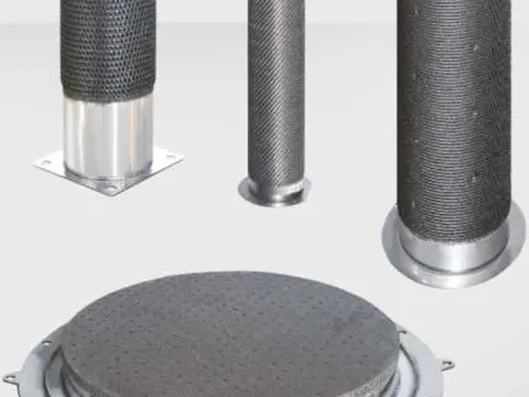
4.2. Vibration damping and noise reduction components
Vibration and noise control is an unavoidable engineering issue in the evolution of modern mechanical equipment toward higher speeds, higher power, and greater comfort. From the physical essence of vibration reduction and noise control, any damping material needs to convert mechanical energy into heat for dissipation; different materials accomplish this conversion through different microscopic or mesoscopic mechanisms.
For porous damping materials, internal friction originates from multiple channels. The first channel is the micro-yield deformation of pore walls. Under cyclic loading, even if the nominal stress is far below the macroscopic yield strength, the ligaments at the smallest cross-sections around pores may still locally reach plastic deformation conditions. This highly localized micro-plasticity dissipates a small amount of work in each loading cycle, converting it into heat. The second channel is viscous friction of the fluid within pores. When a porous body is subjected to vibration, the pore volumes periodically expand and contract, driving the reciprocating flow of gas or liquid inside the pores [114]. The fluid forms velocity gradients near the pore wall due to viscosity, generating viscous shear forces that transfer macroscopic vibrational kinetic energy stepwise to microscopic molecular thermal motion. The damping contribution of this mechanism is closely related to frequency and pore structure—the smaller the pore size and the more tortuous the flow channels, the greater the contribution of viscous dissipation. The third channel may be more specific to the system: the reversible motion of antiphase boundaries (APBs) in the ordered structure under cyclic stress also contributes a portion of interfacial internal friction [6]. The superposition of these three mechanisms gives porous a stable and appreciable internal friction value (characterized by the loss factor , typically between and ) from room temperature to , far higher than that of dense ( generally less than ), approaching the room-temperature damping level of some polymeric damping materials, yet with vastly superior temperature stability [114].
Acoustic losses and damping internal friction share the same physical origin—both lie in irreversible energy dissipation—but differ in engineering expression. When a sound wave impinges on a porous body, part is reflected at the surface, and part enters the pore network. The sound wave entering the pores undergoes multiple reflections and scattering between pore walls, with each reflection accompanied by partial energy absorption (through the aforementioned micro-yield and viscous mechanisms). A more critical effect is the acoustic impedance gradient mismatch: the acoustic impedance (product of density and sound speed) of porous lies between that of dense metal and air. When the structure is designed with multiple layers of porosity gradients, the sound wave continually generates reflection components at the interfaces of layers with different impedances, effectively "trapping" the incident wave inside the material to undergo more cycles of absorption and dissipation. This gradient impedance matching strategy is effective over a broad frequency range, overcoming the limitation that a single uniform porous layer is efficient only for a specific frequency band (roughly where pore size is comparable to wavelength) [114].
In vibration isolation scenarios for engineering machinery power sources, porous damping elements are typically embedded in the form of pads or bushings in engine mounts, transmission suspensions, or muffler hangers. The operating temperatures at these locations often reach due to proximity to exhaust manifolds or turbochargers. Traditional rubber or polyurethane damping materials undergo thermal degradation, hardening, or even carbonization at these temperatures, with their damping effectiveness sharply declining. Aluminum foam or foamed aluminum, although possessing some temperature capability, undergoes significant softening above with modulus and strength decaying manyfold, losing load-bearing capacity. Porous does not undergo any microstructural transformation below , and the temperature dependence of its damping performance is far lower than that of polymeric materials—within the interval, the change in does not exceed —making it a strong candidate for long-term damping solutions under thermal-mechanical coupling conditions [6, 114].
Flow-field noise reduction is another distinctive application direction. Pneumatic system exhausts (e.g., exhaust from pneumatic tools, exhaust ports of pneumatic brake systems) generate high-intensity broadband noise. Placing porous silencing elements in the exhaust path uses the pore network to disperse a concentrated jet stream into countless tiny streamlets; on one hand, this reduces flow velocity and thus reduces turbulent noise sources; on the other hand, the airflow passes through the viscous dissipation of pore walls, converting pressure energy into heat, functioning as a dissipative muffler. Compared with traditional reactive mufflers (e.g., silencers filled with glass wool or mineral wool), porous silencing elements do not suffer from fiber blowout or performance degradation after moisture absorption, and are especially suitable for industrial pneumatic systems requiring long-term maintenance-free operation [114].
Structural component vibration damping is a further extension of this application area. Machine tool beds, precision stage bases, bearing housings of high-speed rotating machinery—these structural components are subjected to broadband excitation during service, and the resonance response of the structure can directly affect machining accuracy or operational stability. Integrating porous in the form of sandwich panels or local inserts into dense structural components can significantly increase the structural damping ratio without substantially sacrificing overall stiffness. The principle is similar to constrained-layer damping treatment, but the interface between the damping layer and the base layer is transformed from a viscoelastic layer into a metallurgically bonded interface (achieved through sintering or welding), which does not undergo delamination failure at elevated temperatures. This is of unique value for structural damping design that must serve at high temperatures (e.g., aero-engine test rigs, gas turbine accessory mounting bases) [114].
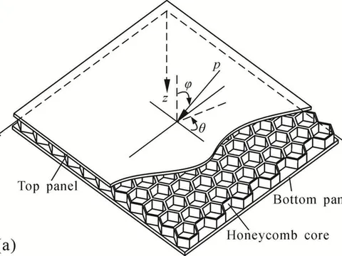
4.3. Heat exchange and heat dissipation components
Thermal management is a cross-scale common requirement in mechanical engineering—from chip-level microelectronic heat dissipation to equipment-level heat exchangers to system-level building thermal management, all start from the thermophysical properties of materials. The unique value that porous bodies provide in the thermal management domain lies in the ability, through flexible regulation of pore structure, to switch between the two seemingly contradictory functional modes of "efficient heat transfer" and "effective thermal insulation"—or more precisely, to realize differentiated thermal management functions in different regions or directions of the same component [63, 68].
From the underlying logic of heat transfer enhancement, the involvement of a porous skeleton in convective heat transfer can be decomposed into two parallel mechanisms. The first is the extension of geometric area. The specific surface area of porous bodies typically ranges from hundreds to thousands of , which means that in the same installation space, the solid-fluid contact interface area can be increased by one to two orders of magnitude compared with a bare cavity or flat-plate heat sink. The second is the restructuring of the flow field. When a fluid passes through the tortuous pore channels of a porous medium, the flow direction is constantly forced to change, and the boundary layer is repeatedly disrupted and rebuilt at the bends of pore walls—this continuous disturbance suppresses the tendency of the thermal boundary layer to thicken along the flow direction, keeping the local convective heat transfer coefficient at a high level [68]. Under the same flow rate and temperature conditions, the convective heat transfer coefficient inside a porous medium can reach times that in a smooth channel. For tubular heat exchangers filled with porous bodies, experimental data show that in the range , the Nusselt number can be increased by a factor of compared with an empty tube, and the overall heat transfer enhancement ratio (net benefit after accounting for increased flow resistance) lies between and , superior to metal foam aluminum of the same porosity [68].
In the heat-sink components of engineering machinery (e.g., hydraulic oil coolers, engine oil radiators), the entry point for porous heat-exchange elements is not to replace the main heat exchanger, but to serve as "functional enhancers" in locations where space is extremely compact, heat dissipation demand is concentrated, and reliability requirements are stringent. For example, embedding a porous ring element into the guide-sleeve section of a hydraulic breaker drill rod uses its interconnected pore network to extract internal friction heat through forced circulation of oil, reducing the local temperature from above to below , effectively extending the service life of the guide sleeve and seals [68]. The feasibility of this scheme relies on two points: the formability of porous elements (complex ring-shaped parts can be near-net-shaped by powder metallurgy) and their chemical inertness in high-temperature oil (not catalyzing oil oxidation, not generating organic acid corrosion).
High-temperature pipeline thermal protection layers are another typical application of porous functional insulation. In the flues of metallurgical steelmaking converters, the regenerator pipelines of glass melting furnaces, and the FCC regenerator standpipes in petrochemical industries, the internal medium temperature reaches , while the external must maintain a safe and operable temperature (usually below ). Traditional insulation solutions involve wrapping with calcium silicate or ceramic fiber blankets; the former has heavy density and high labor intensity for installation, while the latter gradually devitrifies and powders at high temperature, causing insulation performance to degrade [118]. The value of porous insulation layers lies in the ability to provide a coefficient of thermal expansion matching that of dense structural steel and far superior mechanical integrity compared with ceramic fiber blankets at a relatively low apparent density (). Its insulation principle is as follows: high porosity () reduces the effective thermal conductivity to , and residual air in the pore channels (thermal conductivity ) further interrupts the heat flow path [63]. In terms of process realization, the porous can be prefabricated into tile-shaped or half-pipe segments and then wrapped around the pipe exterior by welding or mechanical fixing, with gaps filled using high-temperature-resistant sealant. This structure provides reliable insulation while avoiding the problem of local collapse failure of fibrous materials due to mechanical impact or construction trampling.
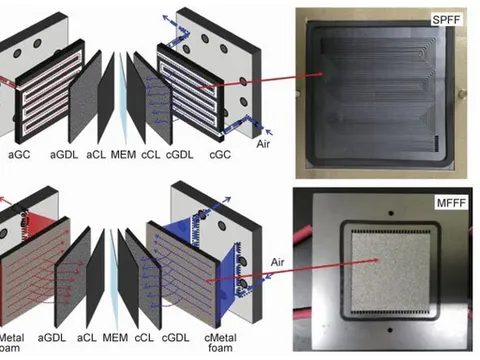
Porous flow-field distributors for fuel cells are a relatively emerging application exploration. Proton exchange membrane fuel cells (PEMFCs) and solid oxide fuel cells (SOFCs) both require uniform distribution of reactant gases (hydrogen or hydrogen-rich syngas, air or oxygen) to the electrode-electrolyte interface, while simultaneously rapidly expelling generated water vapor or . The traditional way to realize this "flow field" function is to machine serpentine or interdigitated grooves on metallic or graphite bipolar plates. Porous medium flow fields offer an alternative flow-channel design concept: using the pore network itself as the gas distribution channel, the reactant gases pass through the porous body in the counter-flow bipolar plate chamber to reach the catalyst layer [15]. This design eliminates the "land-channel" effect inherent in conventional grooved flow fields—where the catalyst layer region directly under the channel has abundant reactant gas, while the region under the land between channels suffers from local starvation due to long diffusion distances—thereby significantly improving current density and reaction uniformity. The attraction of porous bodies in this application lies in their electrical conductivity (can serve as part of the current collector) and potential corrosion resistance in the acidic PEMFC environment (the passivation ability of silicon can compensate for the corrosion tendency of iron to some extent), but the key lies in whether the uniformity of porosity and pore size can be controlled to the strict levels required by fuel cells (porosity tolerance typically required within , and the pore-size distribution over the entire plate must be highly uniform) [83]. This is precisely where additive manufacturing and precise sacrificial templating hold advantages over traditional reactive sintering—the former can programmatically control the pore size at each spatial location, achieving true full-scale uniformity or on-demand gradient pore designs.
4.4. Catalyst supports and wear-resistant coatings
In the two surface-function categories of catalysis and wear resistance, porous bodies act in two different forms—"monolithic porous skeleton" and "dense-porous composite coating"—but both share the same underlying material logic: the system can provide a chemically tunable, mechanically self-supporting, heat-resistant, high-surface-area platform.
On the catalytic-support side, the core demands are the simultaneous satisfaction of specific surface area, thermal stability, and chemical compatibility. Chapter 3 has already discussed, from a performance perspective, the preliminary experimental evidence of as a support for active components such as . What needs to be added here is that in practical industrial tail-gas treatment scenarios, catalyst supports also need to meet a harsh condition often overlooked in laboratory research—formability. Industrial catalytic reactors (whether fixed-bed or monolith) require supports with defined macroscopic geometric shapes (spherical, cylindrical, honeycomb, ring-shaped) and sufficient crush strength to withstand the static load of the catalyst packed bed and the dynamic load of fluid scouring. porous bodies can be near-net-shaped into spherical particles (diameter ) or monolithic honeycomb blocks by powder metallurgy, requiring no subsequent machining before direct impregnation of active components and loading. This forming route is highly compatible with the existing production processes for alumina or activated carbon catalyst supports in industry, reducing the cost of production changeover [93]. In the high-temperature upstream zones () of diesel oxidation catalysts (DOC) and selective catalytic reduction (SCR) systems, porous supports have the potential to replace vanadium-based titanium dioxide catalyst supports approaching their temperature limits—the latter experience catastrophic specific-surface-area loss under continuous operation above due to crystal transformation and rutile formation. supports, having no solid-solid phase transformation, suffer specific-surface-area decline mainly through the physical process of sintering neck growth, rather than chemically driven phase-transformation collapse [93].
Focusing on the mass-transfer enhancement dimension of catalytic supports, the three-dimensional interconnectivity of the porous network greatly shortens the diffusion path for reactant molecules to go from the bulk gas phase to the catalyst active sites. If the catalytic active component is loaded only on the pore-channel surface without filling the pores, the diffusion state of the reactants within the pores is in the Knudsen or transition diffusion regime, and the effective diffusion coefficient is proportional to the pore radius. By controlling the main pore channels to the range of tens of nanometers to microns, which is optimal for mass transfer, porous bodies can avoid sub-nanometer blind pores that impair permeability [93]. For first-order reactions, this mass-transfer enhancement directly manifests as the apparent rate constant approaching the intrinsic rate constant, and the catalyst effectiveness factor can be maintained at a high level, thereby reducing the loading of precious metal active components—this is the fundamental logic for achieving an economic breakthrough in catalyst supports.
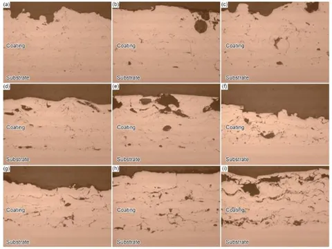
Turning to the wear-resistant coating field, the potential of alloys as surface-engineering materials belongs to a different technical route from their monolithic porous form. In critical friction pairs of hydraulic transmissions (e.g., cylinder-valve plate interface of piston pumps, spool-valve sleeve clearance of servo valves), wear and corrosion often advance the failure process in a coupled manner. Clearance corrosion leads to increased surface roughness, which in turn accelerates abrasive wear and adhesive wear; wear exposes fresh metal surfaces which conversely accelerate corrosion. The traditional strategy for combating this "wear-corrosion" coupled failure is to use high-alloy stainless steels or apply hard chromium plating. alloy coatings provide an alternative option: depositing alloy powder onto a steel substrate by oxy-acetylene flame spraying or plasma spraying to form a coating containing uniformly distributed micropores [113, 117]. The wear resistance of the coating comes from the high hardness of the phase (approximately ) and the long-range lattice frictional force of the ordered structure; corrosion resistance comes from the passive film formed by silicon in the medium; and an appropriate content of closed micropores in the coating (porosity ) can serve as oil reservoirs, providing secondary oil supply under boundary lubrication or lean-oil conditions, reducing the friction coefficient and wear rate [113].
This "oil-storing micropore" design already has mature industrial precedent in cylinder-liner-piston-ring friction pairs (e.g., laser-honed cast iron cylinder liners), but when applied to planar friction pairs such as hydraulic pump valve plates, higher requirements are placed on pore size (typically requiring diameter), distribution uniformity, and coating-substrate bonding strength. By controlling the particle size and morphology of the spray powder and the process parameters of post-spray localized laser remelting, the size and distribution of micropores can be regulated. The metallurgical bonding strength—i.e., upgrading the interface between coating and steel substrate from mechanical interlocking to an elemental diffusion layer or even micro-area fusion welding—is the fundamental guarantee for long-term service. During the thermal spraying process, alloy and a carbon-steel or low-alloy steel substrate can undergo mutual diffusion of iron atoms at the interface, forming a transition layer approximately a few microns thick, whose strength is far higher than the mechanical bonding interface of ceramic coatings (e.g., or ) with metal substrates [117]. This point is critically important for scenarios that bear high contact stresses (typical hydraulic pump valve-plate contact stress is in the tens to hundreds of ) and forbid total coating delamination. In engineering case studies, hydraulic pump valve plates with coatings exhibited lower wear amounts against the piston in accelerated bench tests, and after of continuous testing showed no signs of coating interface delamination, whereas the comparative hard chromium plating developed localized peeling after about [113].
5. Existing research and application challenges
Through the foregoing structural regulation, property characterization, and application exploration, the basic profile of porous materials has become relatively clear. However, from "feasibility" in the laboratory to "reliability" in engineering, several hurdles that have not yet been overcome still lie in between. Currently, the core challenges facing this material system can be summarized into five levels, which are not isolated but interrelated and mutually constraining: the design capability of pore structure determines whether the theoretical upper limit of performance can be reached, while the high-porosity-high-strength inversion relationship delineates this upper limit; the absence of surface protection reduces the real service life of the material in harsh conditions far below the theoretical value; the uncontrollability in scaled-up production means that the performance benchmarks obtained in the laboratory are difficult to reproduce on the production line; the superposition of these problems has ultimately led to the significant "valley of death" between the technology readiness level and engineering application.
The bottleneck of precise pore-structure design is the most upstream constraint. The pore-forming mechanism of traditional powder metallurgy essentially belongs to a passive topological generation of "particle packing—sintering neck growth"—the size, shape, and spatial distribution of pores are jointly determined by the original powder particle size and morphology, the sintering temperature-time curve, and random fluctuations in local density [12, 19]. Under this route, even if the macroscopic porosity is controlled near the target value, the microscopic coordination number, tortuosity, and throat size of the pore channels remain highly random. The realization of ordered pore structures, such as honeycomb-like regular channels or gradient-pore-distribution filter elements, currently relies on additive manufacturing or sacrificial templating; the former progresses slowly in the system due to the difficulties of melt flowability and solidification shrinkage control, while the template-removal process of the latter faces challenges of carbon residue, cracking, and non-uniform dimensional shrinkage in thick-walled parts [14, 15]. The difficulty of precisely controlling the pore-size distribution directly propagates to the performance end: the batch-to-batch fluctuation of permeability, the dispersion of filtration precision, and the unpredictability of acoustic or damping response all root in this. It can be said that if the transition from "passive pore formation" to "active pore creation" cannot be realized, the potential of this material in high-end filtration and precision damping scenarios will be difficult to fully realize.
The inversion conflict between high porosity and high strength constitutes the material's own physical ceiling. The nature of a porous body dictates that its load-bearing path is a discontinuous three-dimensional ligament network. An increase in porosity implies a linear reduction in the effective load-bearing cross-section, and the power-law relationship given by classical porous mechanics models is only the lower-limit description of the problem—in reality, stress concentration at pore sharp corners and inherent defects in ligaments often cause the strength drop to be even more severe [1, 19]. When porosity exceeds half, the compressive strength of porous bodies has dropped to one-tenth or even less of the same-composition dense material [51]. This inversion relationship imposes severe constraints on lightweight design: pursuing high porosity in vibration-damping or thermal-insulation scenarios necessarily sacrifices load-bearing capacity, and there is currently no effective synergistic solution—ideas such as metal fiber reinforcement and gradient-porosity composite design are still in the conceptual stage, with practical mitigation effects far below expectations. How to continue pushing up porosity without losing too much strength is an unsolved knot in material design.
The dilemma of internal pore-surface protection under complex conditions pulls the real service life far below the theoretical value. Surface engineering is already a mature field for dense materials, but encounters fundamental obstacles when applied to porous bodies. Coating technologies, whether electroless plating, electroplating, sol-gel, or vapor deposition, have extremely limited effective penetration depth inside pore channels. When the pore size decreases to the micron level and the pore tortuosity increases, the mass transfer of precursor molecules to the depth of the pores is limited by slow diffusion mechanisms, resulting in an unacceptably large gradient in coating thickness along the pore wall [81, 82]. Even more tricky is that once a coating on the internal pore wall develops local cracking or spalling due to thermal cycling stress or fluid scouring, the exposed fresh surface becomes the starting point of a galvanic corrosion program, accelerating ligament perforation failure. Under service environments of coupled thermal-mechanical-chemical multi-fields, current surface treatment technologies cannot yet provide a protective-layer solution that is dense, uniformly covers all pore walls, and can serve stably over the long term. This shortcoming causes the real service performance of porous materials in areas where they should have strong advantages, such as high-temperature corrosive filtration and corrosive slurry separation, to be discounted.
The problem of performance consistency in scaled-up production makes the transfer of laboratory results to the production line extremely difficult. When moving from a laboratory sintering furnace to an industrial production-scale furnace, the spatial distribution of the thermal field and force field is no longer uniform. Temperature gradients within the furnace chamber, deviations in heating rate, and the non-synchronized shrinkage stress of the green compact during sintering will all introduce microstructural variations within and between batches—grain size, degree of order, and pore topology can exhibit statistically significant deviations even within a product on the order of ten centimeters [20]. More subtly, the reactive sintering of is accompanied by thermal effects from compositional diffusion and phase transformations, and localized exotherms or endotherms can exacerbate these deviations. The final result is that the permeability-strength benchmark curve obtained on laboratory samples becomes an unacceptably wide distribution band on mass-produced filter elements, severely limiting product qualification rates. Behind this problem is the inherently multi-field coupled nonlinearity of reactive sintering—using homogenized process parameters to match non-uniform physical fields is itself a thankless pursuit.
The layered stacking of the above difficulties ultimately locks porous materials in the transition zone of the technology readiness level. Laboratory-scale performance verification has long been completed, but system-level verification under simulated real working conditions is severely insufficient. Materials researchers are accustomed to using constant temperature, constant flow, and single medium as test conditions, whereas the engineering field throws out a random combination of temperature fluctuations, pressure pulses, medium composition changes, mechanical vibrations, and operational errors [21]. The lack of closed-loop assessment data over thousands of hours and the lack of comprehensive cost-life-reliability comparison studies with existing mature solutions keep end-users' adoption decisions for this material perpetually at a wait-and-see stage. Crossing this gap no longer requires a single academic breakthrough, but rather industry-academia-research joint medium-scale pilot validation input with specific equipment as the carrier—and this is precisely the weakest link in the current porous materials field.
6. Future development directions
6.1. Multi-scale pore structure optimization
The pore-forming logic of traditional powder metallurgy is limited by the inherent characteristic scale of a single pore-forming mechanism (e.g., particle packing, pore-former decomposition, or partial dissolution), and can only generate pore channels within a relatively narrow pore-size interval. When facing the triple demanding requirements of "high throughput, high precision, and high surface activity," this unimodal pore structure inevitably falls into the intrinsic game between "fluid mass transfer resistance" and "surface functional loading"—an increase in pore size can widen the flow cross-section and reduce resistance, but at the cost of a precipitous drop in specific surface area and interception precision; a decrease in pore size can trade for abundant active sites and precision sieving capability, but leads to the vast majority of the percolation driving force being consumed in viscous dissipation.
The fundamental strategy to escape this dilemma lies in the deep coupling of multiple pore-forming mechanisms [14, 15, 44]. Specifically, integrating sub-millimeter main transport channels formed by particle packing, micron-scale window pores left by pore-former pyrolysis, and nanoscale interconnected throats generated in situ by solid-state reactions into the same thermal processing history constructs a nano-micro-milli cross-scale hierarchical pore network. The ideal blueprint of this configuration can be likened to the hierarchical transport systems of nature—coarse main veins responsible for cross-regional long-range transport, progressively branching branch veins covering the entire territory with minimum resistance, and terminal micro-nano gaps carrying interface reactions and molecular recognition functions with their huge specific surface areas [31, 35, 39]. In cutting-edge devices such as gas separation membranes, flow electrodes, and catalyst supports, such hierarchical pores are expected to simultaneously achieve bidirectional gains in permeation flux and physicochemical selectivity, anchoring the stringent requirements of service boundaries on pore structure.
The difficulty in tackling this direction lies in: the dynamic windows of multiple pore-forming mechanisms nest with each other, requiring precise customization of the size ratio, spatial correlation, and topological connection order of pores at each level, avoiding "dead-end pores" or "channel crosstalk" caused by disconnection between levels; computational fluid dynamics-assisted network design, as well as process iteration guided by high-temperature in-situ microscopy and tomography, will become the key to solving the problem of multi-scale synergistic regulation [101, 109].
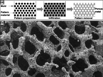
6.2. Multi-component composite modification
The ligament skeleton of porous bodies bears the complex triangular tension among mechanical integrity, thermodynamic stability, and chemical inertness: increasing silicon content can strengthen the matrix's oxidation resistance and high-temperature hardness, yet sharply raises the ductile-to-brittle transition temperature, making room-temperature brittleness a fatal shortcoming [60]; densification of the ligament is the source of strength, yet naturally conflicts with the design pursuit of high porosity; a single-phase solid solution may retain partial ductility, but its high-temperature creep resistance and corrosion resistance are far inferior to multi-phase structures with dispersed second phases. This means that relying solely on the adjustment of the binary composition can no longer touch the ceiling of synergistic optimization of multiple performance objectives, and multi-component composite modification strategies must be introduced.
The first measure is rare-earth micro-alloying—trace amounts of rare-earth elements, by virtue of their large atomic radius and strong grain-boundary segregation tendency, can exert a modification and purification effect during sintering: capturing impurity oxygen and sulfur to form stable compounds, purifying the internal interfaces of ligaments; meanwhile, they segregate to the pore-wall surface, reducing the surface diffusion coefficient, and suppress capillary coarsening and pore-channel collapse of ligaments in high-temperature service [90]. The second measure is solid-solution and precipitation strengthening by transition-metal elements—elements such as , , and dissolved in the matrix produce lattice drag effects, and when combined with nanoscale carbides or intermetallic compounds precipitated under appropriate heat-treatment regimes, can construct a progressive strengthening gradient on the ligament from room temperature to high temperature. The third measure is grain-boundary and dislocation pinning by nanoscale heterogeneous phases—in-situ synthesized dispersed particles such as , , or distributed at grain boundaries and sub-grain boundaries of ligaments effectively inhibit grain-boundary sliding and dislocation climb at high temperature, enhance creep resistance, and act as obstacle points on the crack propagation path, improving fracture toughness [104, 109].
The synergistic implementation of the three aims to achieve the cross-scale superposition of solid-solution strengthening, precipitation strengthening, and interface strengthening on the microscopic carrier of porous ligament, thereby alleviating to a considerable extent the multiple dilemmas of high-silicon intrinsic embrittlement, strength decay at high porosity, and performance degradation in high-temperature corrosive environments. The core challenge of this direction lies in the fact that the phase-selection thermodynamics and kinetic windows of multi-components with the matrix under non-equilibrium sintering conditions are extremely narrow, urgently requiring the establishment of reliable multi-component phase-diagram-driven process-property relationship maps to rationally guide the coupled design of composition and heat-treatment regimes.
6.3. Intelligent precision manufacturing
The control of pore structure by traditional powder metallurgy is highly dependent on the gross average settings of process parameters, but the multi-field coupled nonlinearity of the reactive sintering process causes homogenized parameter inputs to output non-homogeneous microstructural results—the inevitable price of "black-box" operation [20, 101]. The introduction of additive manufacturing technology offers a fundamentally new path to break this predicament. Its core advantage lies in the spatial layer-by-layer reconstruction capability: a three-dimensional component is discretized into a series of two-dimensional slices with controllable thermal history, and the solidification of each layer occurs within a relatively convergent small space-time domain, which greatly reduces the microstructural drift driven by internal thermal gradients in thick-walled parts. More importantly, additive manufacturing pushes the design boundary of pore structure to a level directly driven by digital models—complex gradient pore types, irregular internal flow channels, and biomimetic topological skeletons, which are difficult to achieve with traditional processes, can all be directly transformed into physical entities through scanning-path algorithms [15, 44].
The key step toward "intelligentization" lies in introducing online monitoring and closed-loop control of melt-pool thermodynamics: using pyrometers or thermal imaging cameras to collect temperature-field characteristics of the forming zone in real time, using machine learning algorithms to instantly compare them with a preset process window, and sending adaptive correction commands to the execution end such as laser power, scanning speed, or substrate preheating [110]. This "perception-decision-execution" closed-loop architecture is expected to shift the preparation paradigm of porous bodies from "empirical trial-and-error of parameter screening" to "online precise driving of microstructure," fundamentally converging the batch-to-batch dispersion of pore characteristics and mechanical-permeation properties, and driving this material system toward the manufacturing dimensions of high precision, homogeneity, and standardization. It must be recognized that the material-inherent problems of systems in additive manufacturing, such as poor melt flowability and strong solidification-cracking sensitivity, remain prominent; developing dedicated powder composition systems and composite preheating strategies suitable for powder-bed fusion processes is a prerequisite topic that must be tackled before this direction can land.
6.4. Expansion into extreme-condition applications
The vast majority of current research on porous materials still uses constant temperature, constant flow, and single-medium as the performance evaluation scenario, which has an essential gap with the multi-parameter coupled fluctuations of real service sites [21, 111]. In high-temperature sulfur-containing flue gas filtration, the material needs to simultaneously withstand temperature cycling of , corrosive gas flow scouring containing and , and continuous erosion wear by fine dust; in deep-sea hydraulic system oil purification, it must tolerate tens of -level hydrostatic pressure and low-cycle fatigue superimposed by pulsating flow fields; in fuel atomization components of special power systems, it faces the synergistic siege of intense thermal-mechanical-chemical triple-field coupling, oxidation-sulfidation-carburization composite corrosion, and fretting wear.
Failure under these extreme conditions is rarely the result of a single mechanism, but often the product of the resonance of multiple degradation processes—micro-cracks initiate on the pore-wall surface due to thermal expansion mismatch, the bare metal at the crack root becomes the preferred site for localized corrosion, the volume expansion of corrosion products further aggravates pore-channel blockage and ligament stress concentration, and finally triggers ligament fracture and functional collapse [67, 81]. Systematically elucidating the microstructural evolution path under such multi-physics-field coupling, and establishing a full-life-cycle mapping model from initial damage to ultimate failure, is the prerequisite for reasonably formulating service-life prediction and safety-redundancy design criteria. More importantly, this direction shoulders the strategic mission of finding the most "irreplaceable" killer application for porous materials—when the unique advantages of a material are highly coupled with the core pain points of a particular harsh working condition, the threshold for engineering adoption will be greatly lowered [120]. Therefore, extreme-condition verification should not merely be the terminal inspection of performance, but should become the feedback engine for material optimization design: real-time feedback of failure weak links exposed under real complex media to the front end of pore-structure design, matrix-composition control, and preparation-process optimization, forming a "design-preparation-assessment-improvement" spiral ascending closed loop.
6.5. Industry-academia-research collaborative landing
The aforementioned four directions focus respectively on bottleneck breakthroughs at the technical dimension, yet the deepest obstacle to the engineering of new materials often lies not in technology itself, but in the institutional fractures along the innovation chain. The evaluation systems of universities and institutes naturally gravitate toward pursuing novelty, academic paper publication, and extreme performance records at the laboratory scale; enterprises instinctively care about cost controllability, batch consistency, and yield and efficiency under mass-production conditions—what is missing between the two is an intermediate body capable of catalyzing the sparks of laboratory innovation into commercially viable product prototypes, and this is the strategic value of pilot platforms [118, 120].
Different from the mission of basic research laboratories of "proving it can be done," the core task of a pilot platform is "proving it can be done economically and consistently." This requires that for the medium-scale pilot verification of porous materials, one cannot focus only on the functional parameters of trial-produced samples, but must consciously and systematically diagnose and tame the process scale-up effects—including the uniform forming of large-sized green compacts, the gradient compensation of temperature fields in large-furnace sintering, and the batch-stability control of large-scale powder preparation—so as to substantially advance the technology readiness level from the current laboratory-validation stage to the threshold of system-level validation or even pilot production. Synchronously, for this material system to enter the mainstream engineering material selection horizon, a set of widely accepted industry-standardized evaluation specifications is still lacking. The mechanical testing and permeability evaluation standards for dense metals cannot be simply applied to porous bodies: the statistical definition method of pore-size distribution, the size-effect correction of mechanical properties, and the comprehensive performance-representation system among permeability-filtration precision-dirt-holding capacity, all urgently need consensus to be formed.
Relying on an innovation consortium deeply integrating "industry-academia-research-application," with universities outputting mechanism cognition, institutes responsible for standard development, enterprises driving product transformation, and end-users providing closed-loop service data feedback, a synergistic ecology with multiple entities supporting each other can be formed, thereby substantially breaking down industrialization barriers and driving the porous system toward high-reliability large-scale continuous manufacturing. The key in this process is to ensure that the endpoint of "research" no longer stops at paper publication, but solidifies into mature material entries incorporated into equipment management specifications and repeatedly reproducible.
7. Conclusions
Centering on porous materials and following the main line of "preparation-structure-performance," this study has obtained several fundamental cognitions. In controllable preparation, it was demonstrated that by utilizing the unbalanced interdiffusion and Kirkendall vacancy coalescence, three-dimensionally interconnected pores can be generated in situ during sintering; a content of and a sintering temperature near the eutectic point represent the optimal balance window for pore-forming rate and ligament integrity. Regarding the pore-structure-function correlation, it was clarified that pore-size distribution, throat size, and tortuosity jointly determine the permeability and filtration characteristics, and that the interconnectivity tends to saturate when porosity exceeds about , with further permeability gains mainly coming from ligament refinement. Mechanical studies indicate that the synergistic effect of the intrinsic brittleness of high- ligaments and the stress concentration at pore walls leads to the absence of a plasticity plateau, and thermal-shock cracks preferentially initiate at -enriched zones on large pore walls, pointing out directions for reliability design. Functional verification confirmed that above , the oxide film undergoing repeated cracking-and-healing deviates from the parabolic law, but the porous network can vent corrosion products, avoiding the blistering and spalling common in dense materials, thereby achieving a structure-chemistry coupled functional gain.
In bottleneck diagnosis, the inability to reproduce uniform laboratory pore structures on large-sized components, insufficient batch-to-batch consistency, cracking during assembly due to room-temperature brittleness, lack of long-term high-temperature corrosion data, and the absence of full-chain standards constitute the five major barriers to industrialization. To address these problems, this study has proposed several innovative cognitions: unifying pore formation and sintering into a "reactive-sintering synergy window" to avoid the dilemma of over-sintering versus under-sintering; delineating recommended -content intervals for different operating conditions based on the trade-off between brittleness and corrosion resistance; promoting the pore-structure description from average pore size to a multivariate feature vector composed of pore-size distribution curve, connectivity index, and local variation coefficient.
The research still has obvious limitations. The lack of high-temperature in-situ observation means that the key steps of pore-formation kinetics still rely on end-state back-inference; the size effect between laboratory specimens and engineering components has not been bridged; long-term service life models are difficult to establish due to insufficient time scales; and the assessment of full-life-cycle cost and manufacturability remains at a qualitative level.
Looking to the future, at the academic level, it is necessary to shift from empirical trial-and-error to mechanism-driven rational design, using multi-scale simulation to answer fundamental propositions such as the pore-morphology selection rules under multi-component systems, the constitutive behavior and interfacial toughness of membrane layers, and the damage accumulation under multi-field coupling. In terms of technical breakthroughs, efforts should be concentrated on breaking through the four barriers of large-size microstructural homogenization, strengthening-toughening, reproducibility assurance, and joining and packaging. Engineering introduction should adopt a progressive strategy of "low-risk first, high-value pull," accumulating experience from scenarios such as industrial furnace dust removal, and gradually penetrating into cutting-edge fields such as coal chemicals and deep-sea hydraulics. In institutional innovation, constructing an industry-academia-research-application consortium and producing group standards covering pore characterization, mechanical evaluation, and life rating may be a more critical driver of industrialization than single technological breakthroughs. Further ahead, if additive manufacturing and computational design are deeply integrated, the porous system may upgrade from "one usable material" to a "programmable flow-field-regulating platform," at which point competition will shift from cost to design capability. But all projections ultimately need to land on physical objects stably operating at the engineering site—that is the highest reward for materials researchers.
Acknowledgements
This work was supported by the Innovation Training Program for College Students of Shaanxi Province (Project Name: Basic Research on New Fe-Si Porous Functional Materials; Project No. S202510705125), and also supported by Funding for the Comprehensive Reform Project of Graduate Education at Xi'an Shiyou University (2025-X-YJG-006) and Guangxi Key Laboratory of Information Materials & Guangxi Collaborative Innovation Center of Structure and Property for New Energy Materials (Grant No. 231009-K). The financial support and the inspiring academic platform provided by the program are gratefully acknowledged.