I. INTRODUCTION
Ship impact simulations are important for the analysis of safety and structural integrity of ships and offshore marine structure. These simulations play a crucial role in improving ship design, ensuring compliance with industry safety standards, and mitigating risks associated with maritime accidents. However, there is still a gap in research regarding full-scale ship collision analysis, which this study aims to address. Oil spills are a major environmental hazard, and accidents involving oil tankers or barges are the main reasons for such incidents [1]. In many cases, these spills are a direct consequence of ship collisions, which not only lead to severe structural damage but also contribute to environmental disasters. For example, the MV Wakashio oil spill in 2020 led to severe ecological damage off the coast of Mauritius, while the collision of the Baltic Ace in 2012 resulted in significant loss of life and financial setbacks. The substantial market size for ship repair and maintenance services reflects the recurring costs associated with ship damage, including repair expenses and downtime losses. The worldwide market for ship repair and maintenance services was worth USD 35.72 billion in 2023 and is expected to increase from USD 37.14 billion in 2024 to USD 53.23 billion by 2032 [2]. The economic, safety, and environmental consequences of ship collisions are significant, affecting not only ship operators but also marine ecosystems and global trade logistics. These impacts can be categorized as follows, as summarized in Table 1.
| The potential consequences associated with a ship collision | ||
| Economic | Safety | Environment |
| Loss of asset | Injuries | Oil spillage |
| Damage to ship operator's reputation | Loss of life or fatalities | Introduction of invasive species through ballast water |
| Repair costs | ||
| Loss of revenue | ||
As ships are expensive to manufacture, direct collision tests which are destructive in nature and also very expensive, are not feasible. The most viable alternative to such tests is FEA, as it provides accurate and realistic results that are consistent with the experimental results[3] [4]. Collision analysis provides dynamic response of structures and has great importance in designing safe ships and marine structures. Many previous studies have focused on collision analyses using the portions that are adjacent to the impact zones without modeling and meshing the whole ship[5] [6]. However, there is an absence of the study of full body ship analysis. Without the modeling and meshing of a complete ship, it is unclear whether the result will be accurate enough to show the stress distribution properly. Because of the nature of dynamic analysis, simple discrepancies in simulation parameters can cause large deviations in the obtained results[7].
Zhang et al. (2019) derived analytical formulae for energy absorption in ship collisions leading to rupture, and validated their results using finite element analysis and experimental results. Their study supported the use of FEA as an alternative to experimental methods[8].
Aluminum 6061-T6 is widely used as a common construction material in the shipbuilding industry owing to its high strength-to-weight ratio, corrosion resistance, and energy absorption capabilities. Crum et al. (2011) highlighted the growing use of aluminum in modern ship designs, particularly in naval vessels[9]. As the ship we are studying is smaller in size, aluminum is chosen as the construction material.
This study investigates the effects of collisions on a ship structure in which all the structural members are meshed with and without engine mass. As speed greatly affects the impact force [10], the analysis is performed under two different speed settings.
The main objective of this research is to model and mesh a displacement-type vessel with all the structural members and then analyze it with a rigid wall using LSDYNA. The generated stress and internal energy in both these cases are compared.
II. METHODOLOGY
This section outlines the step-by-step process used for the modeling, mesh generation, and simulation of the selected ship.
a) Ship Model Generation and Material Selection
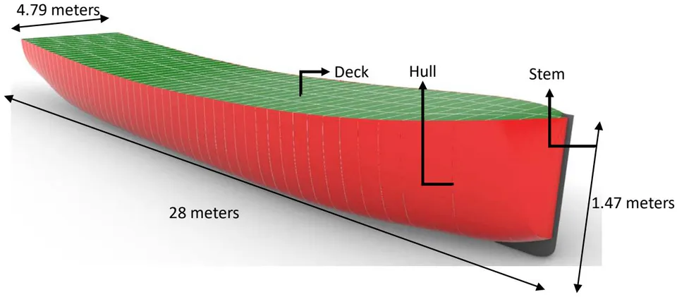
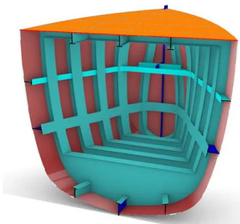
The ship is initially generated using Rhino 3D and its geometric details are simplified as it is a global analysis. In this context, simplification means reducing minor design features that do not significantly affect the overall structural response, ensuring computational efficiency while preserving essential load-bearing elements. The impact on elements away from the collision region is minimal, so they are simplified or removed to focus computational resources on the critical impact areas. The isometric view of the whole model is given in Figure 1. For global analysis, the primary objective is to understand the overall structural response rather than the localized effects of intricate details. Therefore, only essential structural components are retained, while minor design elements are omitted.
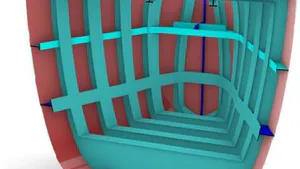
Key internal structural members, such as girders, frames, bulkheads, and pillars, are modeled and are shown in Figure 2 and 3.
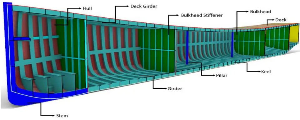
Shell elements with reduced integration (Belytschko-Tsay formulation) are chosen for the modeling to improve computational efficiency while maintaining accuracy. The ship is 28 meters long, 4.79 meters in width, and has a draught of 1.47 meters. To increase the efficiency of the simulation process, non-load-bearing and aesthetic features that do not contribute to impact resistance are removed in accordance with previous studies[11]. Aluminum 6061-T6 is chosen for its high strength-to-weight ratio, corrosion resistance, and energy absorption, making it ideal for impact scenarios. It is lighter than steel while maintaining structural integrity, improving fuel efficiency and speed. Its ductility allows plastic deformation, effectively dissipating impact energy and enhancing crash resistance. These qualities make it a preferred material for naval and commercial vessels needing durability and lightweight construction. Detailed material characteristics [12] are given in Table 2.
| Material Name | Density | Young's Modulus | Poisson's Ratio | Strength Coefficient | Hardening Exponent | Initial Yield Strength |
| Aluminum 6061-T6 | 2700 kg/m1 | 68900 MPa | 0.33 | 410 MPa | 0.05 | 276 MPa |
b) Mesh Generation and Boundary Conditions
Femap and Hypermesh software are chosen to generate mesh to proceed with the FEA. In complex structures such as ships, it is difficult to maintain mesh coupling and connections, making it harder to maintain a good mesh quality. Both of these programs are used to decide which software is better suited for this specific task. The mesh generated by us by Femap is of poorer quality than that generated by Hypermesh, which is compared in Figure 4.
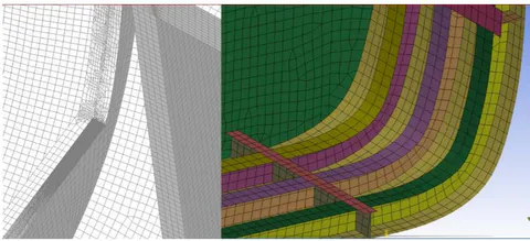
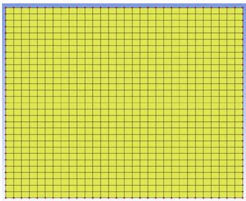
So, generated mesh using Hypermesh is used for the analyses. Three mesh densities are used to obtain more accurate results. As the mesh becomes finer, the accuracy of the non-linear analyses increases so does the calculation time[13]. These densities are shown in Figure 5.
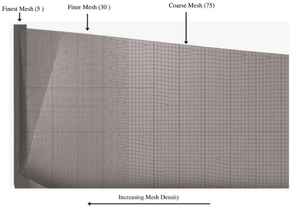
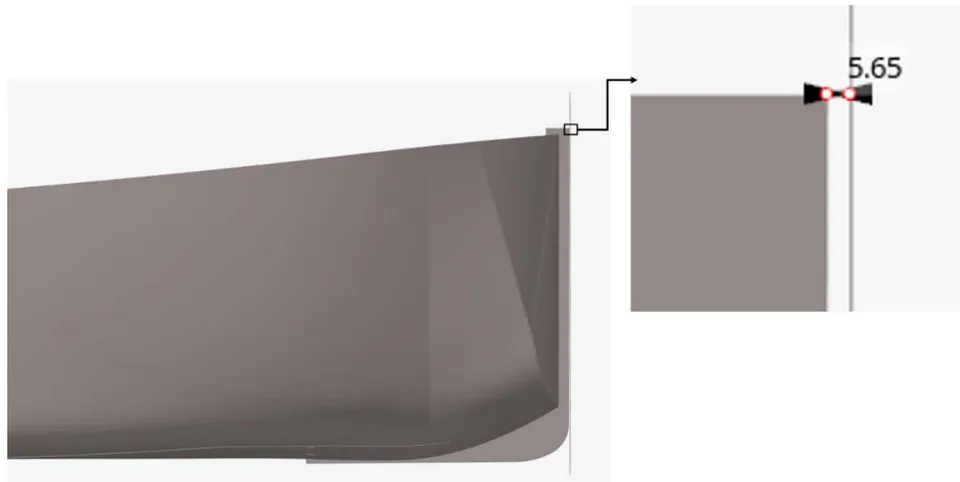
The generated mesh is quad-heavy as quad elements provide greater efficiency in the analysis [14]. Some complex areas have tri-elements, and areas where the mesh density changes also comprise of some triangular elements. Node connectivity was thoroughly checked for all connected elements and parts. Total number of elements is 2,55,859 and node is 2,48,146. Calculated mass is 14.82 tonnes without the engine. A 4-node shell is created for the rigid mild steel wall. The distance between the stem and rigid wall is kept at a minimum (5.65mm) to avoid the node penetration chances and to lessen the computation time. This has been shown in Figure 6.
c) Collision Simulation using LS-DYNA
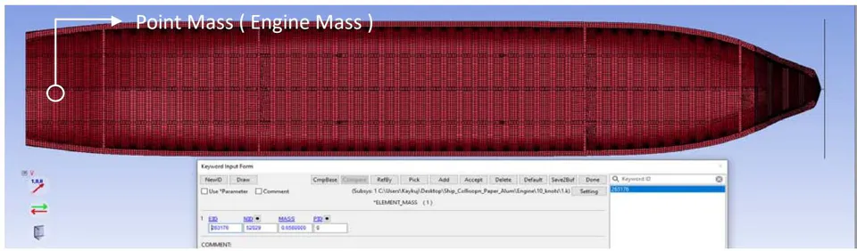
LS-DYNA is an advanced general purpose finite element program which was developed by the Livermore Software Technology Corporation (www.lstc.com). This software package is capable of simulating complex real-world problems within the automotive, aerospace, construction, military, manufacturing, and bioengineering industries [15]. So, for simulation LS-Dyna is chosen. The mesh is exported for use in the solver deck of LS-DYNA. Initially, modal analysis is performed to ensure proper connectivity among all members. The analyses are performed under two speed settings. All nodes comprising the ship are assigned a specified speed. In the first simulation, engine mass is not taken into consideration. Only the mass of the bare ship is used and the stresses are measured. In the second simulation, the engine mass is included as a point mass. The chosen engine is Cummins qsb6.7, weighing 658 kgs, making the total weight of the ship 15.478 tones. As this is a single-screw ship, only one point-mass is added, and the stresses are measured at different time stamps. Subsequently, these values and the regions of plastic deformation are compared.
III. RESULTS
In this section relevant results from the simulation are shown and comparisons are made between different conditions of the ship. In this study, different conditions refer to different simulation scenarios involving variations in speed (5 knots and 10 knots) and internal weight (with and without the engine). These factors influence the ship's energy absorption and structural response during collisions.
a) Energy Absorption and Distribution
The energy curves in Figures9a, 9b, 9c and 9d highlight the variation in energy distribution during the ship's collision at different speeds with varying internal weight (with engine and without it).
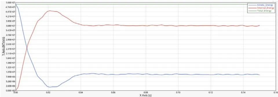
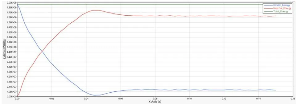
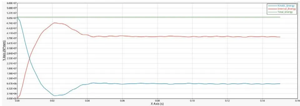
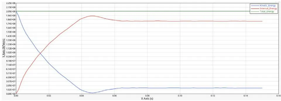
The three key factors, namely - kinetic, internal and total energies are analyzed.
- 5 knots with engine: At the outset of the simulation, the initial kinetic energy is maximum at . Upon collision, the kinetic energy rapidly converts into internal energy in form of deformation and levels at around . The maximum internal energy value is approximately . The total energy remains constant at validating energy conservation.
- 10 Knots without Engine: The initial kinetic energy at starting time is and after decrement, stabilizes at After the collision, the internal energy increases and reaches the peak value at . The total energy remains constant.
- 10 Knots with Engine: The initial kinetic energy at starting time is . mm and after decrement, stabilizes at . After the collision, the internal energy increases and reaches the peak value at . The total energy remains constant.
b) Stress Analysis
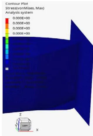
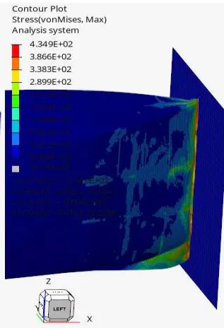
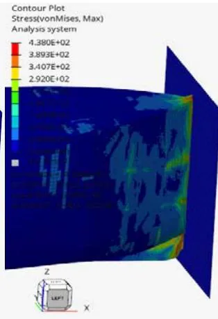
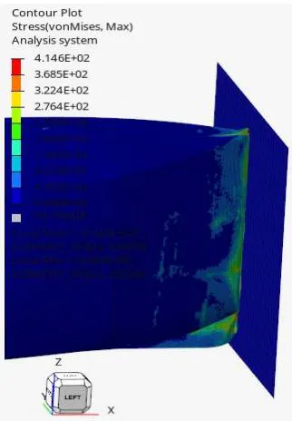
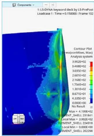
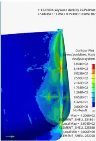
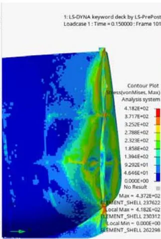
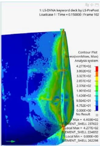
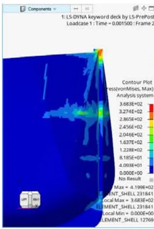
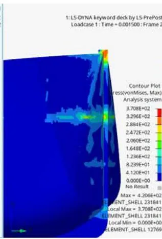
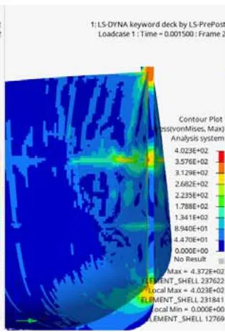
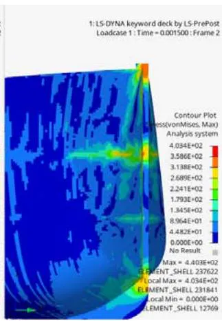
The von Mises stress distribution maps are crucial in understanding the stress responses and locations of plastic deformation. The stresses are shown in Figures 10,11 and 12 at the different times. The Figure 10 shows the wall and for a clearer visualization the wall has been hidden in Figures 11 and 12.
Case Studies:
5 Knots without Engine, Figures 10 (a), 11(a) and 12(a): In this case, the von Mises stress peaks at at initial impact, concentrated around the bow, especially near the stem. The stress diminishes as it propagates through the structure, indicating localized plastic deformation but without significant stress propagation into other parts of the ship. Maximum stress generated is in the stem because of the collision.
5 Knots with Engine, Figures 10 (b), 11(b) and 12(b): The initial impact causes a stress value of at the same locations. Peak value of generated stress is . This is a increase in initial impact stress and a increase in maximum stress to the added engine mass.
10 Knots without Engine, Figures 10 (c), 11(c) and 12(c): The initial impact causes a stress value of at the same locations. Highest stress value is . Which is a significant increase from the previous two. And the deformation is much more noticeable.
10 Knots with Engine, Figures 10 (d), 11(d) and 12(d): The maximum value at the initial collision is . Maximum stress value is . Which is a and increment from the previous simulation at the same speed at initiation and max value respectively.
All the values are summarized in Table 3.
| Speed(Knots) | Addition of Engine Mass | Initial Stress (MPa) | Max Stress (MPa) | Kinetic Energy (N.mm) | Max Internal Energy (N.mm) | Percent Increment from 5 Knots without Engine Initial Impact Maximum Local Stress (%) | Percent Increment from 5 Knots without Engine Max Overall Stress (%) | Percent Increment of Max Internal Energy from 5 Knots without Engine (%) |
| No | 368 | 419.9 | 4.9 × 10⁷ | 4.5 × 10⁷ | 0 | 0 | 0 | |
| 5 | Yes | 370.8 | 420.6 | 5.1 × 10⁷ | 4.7 × 10⁷ | 0.76 | 0.17 | 5.08 |
| 10 | No | 402.3 | 437.2 | 1.9 × 10⁸ | 1.8 × 10⁸ | 9.33 | 4.12 | 305.71 |
| 10 | Yes | 403.4 | 440.3 | 2.0 × 10⁸ | 1.9 × 10⁸ | 9.62 | 4.86 | 326.93 |
The comparison of Von Misses stresses between the two speed settings at 5-knots and 10-knots collisions clearly shows in Figures 10-12 that there exists a relationship between speed and structural deformation. At higher speeds, significantly higher amount of kinetic energy is transferred, leading to greater plastic deformation. The structural components go through higher forces, necessitating design improvements for ships or the inclusion of collision resistance devices.
The addition of engine mass in the ship structure amplifies the energy absorbed during collisions, even more so at higher speeds. Although, the increment is negligible as the engine is quite lightweight. The increased kinetic energy translates into higher internal energy, meaning the structure undergoes more plastic deformation. The stress concentration results emphasize the need for additional structural reinforcements at the effected regions when engine mass is factored into ship designs, especially in the bow and stem.
The results emphasize the need for robust structural design in ships intended for high-speed operations or heavy loads. The higher stress concentrations and plastic deformation in the affected zones observed with increased speed and engine mass suggest that such vessels should incorporate reinforced keel, bulkheads, longitudinal girders and incorporation of shock absorbing mechanisms to better absorb impact energy without compromising the ship's integrity and ensure safety.
Using 6061-T6 aluminum as the material of the ship in the simulations provided valuable insights into the material's performance under high-speed impact conditions. The material exhibited significant plastic deformation, particularly at higher speeds and some deformation at low speed collision.
The fine mesh resolution near the bow was critical in accurately predicting the stress concentrations and potential failure points, suggesting that future simulations should maintain a high mesh density in critical regions to ensure highest possible accuracy in results.
IV. CONCLUSIONS
This study employed FEA to investigate the effects of speed and engine mass on the structural integrity of a displacement-type vessel after collisions. The simulations were conducted at two speeds (5 knots and 10 knots), with and without engine mass, to assess their influence on energy absorption and stress distribution. The results demonstrated a clear trend in how these variables influence the ship's energy absorption and stress distribution. The following conclusions can be made:
At 5 knots, of the total kinetic energy is transferred to the ship structure, while at 10 knots, this increases to . This higher energy transfer at greater speeds results in more significant energy absorption and greater plastic deformation, particularly around the bow and stem. These findings highlight the need for design improvements, such as reinforced structural components or collision resistance devices, to mitigate damage.
The addition of engine mass in the ship structure amplifies the energy absorbed during collisions, even more so at higher speeds. However, the increase in maximum stress is minimal, with a rise at 5 knots and a rise at 10 knots, as the engine contributes relatively little additional weight.
The results emphasize the need for robust structural design in ships intended for high-speed operations or heavy loads. The bow and stem experience the highest stress concentrations because these regions are the first to impact the obstacle, absorbing most of the collision force. The higher stress concentrations and plastic deformation in the affected zones observed with increased speed and engine mass suggest that such vessels should incorporate reinforced keel, bulkheads, longitudinal girders and incorporation of shock absorbing mechanisms to better absorb impact energy without compromising the ship's integrity and ensure safety.
Figures 10-12 shows variation of stresses only in the fore part of the ship in all conditions, which verifies the validity of previous study of Moulas et.al. [3], where they considered modeling of only the fore part.
A finer mesh near the bow is essential for accurately predicting stress concentrations and identifying potential failure points, further confirming the importance of localized meshing strategies in ship collision simulations.
ACKNOWLEDGEMENTS
The authors wish to express their sincere gratitude to all individuals who have provided invaluable support throughout various phases of this research project, both directly and indirectly. Particular acknowledgment is given to the UGC HEQEP Sub Project titled "Strengthening the Research Capabilities and Experimental Facilities in the Field of Marine Structure" (CP#3131), which has significantly contributed to the enhancement of the simulation laboratory facilities. Furthermore, appreciation is extended to the "Basic Research Grant of Bangladesh University of Engineering and Technology" for its financial assistance in advancing the research initiatives.