## I. INTRODUCTION
Methods of chase and parallel approach, as well as proportional approach are widely used methods of aircraft guidance.
In this article, a model of group pursuit is proposed for consideration, when the pursuer moves along a certain trajectory. The target approaches the pursuer by the method of parallel approach. The pursuer releases objects at certain intervals that will pursue the target using the chase method. Objects start from their points on the pursuer's path.
This model is given in the article as an example. The target can approach the pursuer by both the chase method and the proportional method or some other method. The pursuer has little maneuverability, but releases objects that have the ability to homing. In the model of the article, homing objects are released perpendicular to the pursuer's trajectory.
This article describes the modeling of a group survey. Earlier, in the works of R. Isaacs [1], L. O. Petrosyan [2], N.N. Krasovsky [3], the methods of parallel approach and pursuit were described, the concept of a terminal set was introduced. The articles by A.S. Bannikov [4], M.V. Khachumov [5], [6] considered algorithmic aspects of group pursuing. In the works of T.G. Abramyants, E.P. Maslov, V.P. Yakhno [7], Gusyatnikov P.B. [8], [9], [10] the issues of evasion in three-dimensional space were considered. The article by Bogdanov A.V., Filonov A.A., Kovalev A.A., Kuchina A.A., Lyutikova I.V. [11] discussed methods of homing fighters and air-to-air missiles to a group air target. In the work of Nikitchenko S. N., Bassauer A. A. [12], the issues of mutual pursuit of air targets were considered. The article by Kuzmina L.I., OsipovaYu.V. [13] considered the calculation of the trajectory length in pursuit tasks.
In the model of the article, the pursuing objects descend perpendicular to the trajectory of the pursuer. The vanishing angle in the model is chosen as an example. The vanishing angle can be any Descending from the trajectory in the model, sequential and at regular intervals are selected.
Each pursuing object has a detection area formed. In the model, for example, the area is formed as an angle with a vertex at the point where the object is located. The bisector of this angle coincides with the direction of the object's velocity.
## II. PROBLEM STATEMENT
Consider the movement of the pursuer along a certain trajectory on the plane:
$$
\vec {P} (t) = \left[ \begin{array}{c} X _ {P} (t) \\Y _ {P} (t) \end{array} \right].
$$
At time $t_n$, an object is separated from the pursuer's trajectory in a direction perpendicular to the pursuer's velocity vector:
$$
\vec {N} \left(t _ {n}\right) = \left[ \begin{array}{l} - \frac {d Y _ {p}}{d t} (t = t _ {n}) \\\frac {d X _ {p}}{d t} (t = t _ {n}) \end{array} \right]. \tag {1}
$$
Fig. 1 shows that in the model considered in the article, five objects are sent perpendicular from the pursuer trajectory, which after separation will move uniformly and rectilinearly with a speed equal to modulo $V_{G}$.
Fig. 1 is supplemented with an animated image [14], where it will be possible to see how from the pursuer's trajectory at certain intervals objects $G_{n}(t)$ are separated.
The simulation is performed on a section of the plane $[-60:130] \times [0:190]$. The measurement is made in meters. The pursuer moves at a constant speed $V_{P} = 20 \, \text{m/s}$. Objects that break off perpendicular to its trajectory have a velocity $V_{G} = 40 \, \text{m/s}$.
Figure 2 shows a network of parallel lines. As you can see, the initial positions of the pursuer and the target, the pursuer's initial speed determine the entire course of the iterative process. The pursuer's trajectory completely and unambiguously determines the trajectory of the target.
 Figure 1: Simulation of the movement of objects descending perpendicular to the pursuer's trajectory The target
$\vec{T}(t)$ pursues $\vec{P}(t)$ by the method of parallel approach. Figure 2 is supplemented with an animated image [15], where it will be possible to see the movement on the plane of the target and the pursuer.
Let's simulate a situation when objects moving on a plane approach. One object pursues another by the method of parallel approach (Figure 2).
Figure 2 shows the trajectory of the target $\vec{T}(t)$ moving uniformly with a velocity modulus $V_{T} = 25m / s$.
 Figure 2: Modeling of the trajectory of the target moving towards the pursuer by the method of parallel approach
One of the objects, trying to defend itself, releases a group of homing objects.
The task that we have set in this article is to simulate the trajectories of objects $G_{n}(t)$ pursuing the goal $\vec{T}(t)$ using the chase method.
## III. SOLUTION METHODS
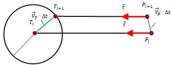
The method of parallel approach can be schematically depicted as shown in Figure 3a, when the target $T(t)$ approaches in parallel to the pursuer $P(t)$.
 a
 b Figure 3: Methods of parallel approach and correction during the chase
Following the iterative scheme shown in Figure 3a, the step of the target trajectory $\vec{T}_{i+1}$ satisfies the solution of the system of equations (2), with respect to the parameter $h$:
$$
\left\{
\begin{array}{l}
\left(\vec{T}_{i + 1} - \vec{T}_{i}\right)^{2} = \left(\left|\vec{V}_{T}\right| \cdot \Delta t\right)^{2} \\
\vec{T}_{i + 1} = \vec{P}_{i + 1} + h \cdot \frac{\vec{T}_{i} - \vec{P}_{i}}{\left|\vec{T}_{i} - \vec{P}_{i}\right|}
\end{array}
\right.
\tag{2}
$$
The target's next step $\vec{T}_{i + 1}$ belongs to a circle of radius $|\vec{V}_T|\cdot \Delta t$, centered at the point of the previous location $\vec{T}_i$, the first equation of the system (2). At the same time, the point of the next position $\vec{T}_{i + 1}$ belongs to a straight line applied to the point $\vec{P}_{i + 1}$ with a guide vector $\vec{T}_i - \vec{P}_i$. The second equation of the system (2) displays the parametric equation of this line.
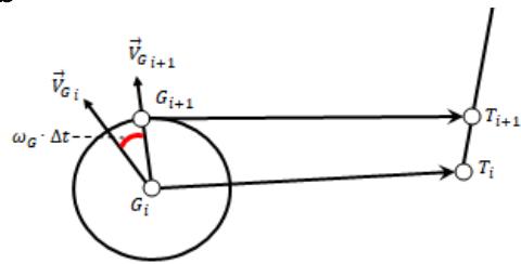
In the chase method, the velocity vector of the object that is catching up is always directed at the object that is being overtaken.
In our case, this is not the case. Let the catching object be located at some time $t_i$ at the point $G_i$, while having a velocity vector $\vec{V}_{G_i}$ (Fig. 3b). After a period of time $\Delta t$, the catching object rotates by an angle $\omega_G \times \Delta t$ and moves to a distance $V_G \cdot \Delta t$, where $\omega_G$ is the angular rotation frequency of the catching object. The angular rotation frequency can be interpreted as:
$$
\omega_{G} = \frac{V_{G}}{R_{G}}
$$
Where $R_{G}$ is the minimum curvature radius of the trajectory of the catching object, that is, the curvature limit.
Consider the motion function of catching up objects $\vec{G}_n$ (Figure 1), when they move along the pursuer's trajectory $\vec{P}(t)$ before the moment of time $t_n$.
If at the moment of time $t_n$ the direction changes to the direction $\vec{N}(t_n)$ specified in (1), then the coordinates of the object $\vec{G}_n$ are determined as follows:
$$
\vec{G} _ {n} (t) = \left\{ \begin{array}{c} \operatorname{ecj} _ {\Pi} t < t _ {n}, \qquad \operatorname{T o} \vec{G} _ {n} (t) = \vec{P} (t) \\ \operatorname{ecj} _ {\Pi} t \geq t _ {n}, \qquad \operatorname{T o} \vec{G} _ {n} (t) = \vec{P} (t _ {n}) + V _ {G} \cdot (t - t _ {n}) \cdot \frac{\vec{N} (t _ {n})}{| \vec{N} (t _ {n}) |} \end{array} \right.
$$
Based on the results of modeling the process of group pursuit of an object by the chase method, a program was written in a computer mathematics system, the results of which are shown in Figure 4.
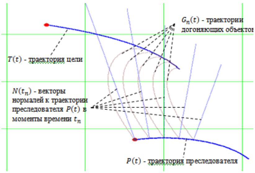 Figure 4: The process of chasing a target by a group of objects using the chase method
An animated image of the group pursuit of a single target by objects that descend perpendicular at certain intervals from the pursuer's trajectory was also produced [16].
The formation of the tracking area of objects $\vec{G}_n$ for the target $\vec{T}$ is performed as follows.
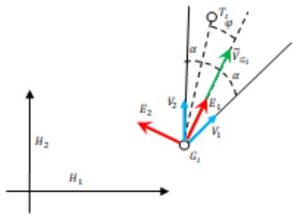 Figure 5: Forming the Tracking Area
A local coordinate system is being created $\left(\vec{E}_1\vec{G}_i\vec{E}_2\right)$ (Figure 5), where $\vec{G}_i$ is the location of the pursuing object at the moment $t_i$. The abscissa vector $\vec{E}_1$ of the object is co-directed to the velocity vector $\vec{V}_{G_i}$. Accordingly, the ordinate vector $\vec{E}_2$ is orthogonal to the velocity vector $\vec{V}_{G_j}$.
The tracking area is given by an angle of magnitude $2\alpha$, the direction of the velocity vector $\vec{V}_{G_i}$ is the bisector of this angle. In the coordinate system $(\vec{E}_1, \vec{G}_i, \vec{E}_2)$ the vectors $\vec{V}_1$ and $\vec{V}_2$ defining the tracking area are determined:
$$
\vec {V} _ {1} = \left[ \begin{array}{c} c o s (\propto) \\- s i n (\alpha) \end{array} \right], \vec {V} _ {2} = \left[ \begin{array}{c} c o s (\propto) \\s i n (\alpha) \end{array} \right].
$$
The conversion of the coordinates of the target point $\vec{T}_i$ is carried out according to the formulas:
$$
\vec {T} _ {i} ^ {*} = \left[ \begin{array}{c} (\vec {T} _ {i} - \vec {G} _ {i}) \cdot \vec {E} _ {1} \\(\vec {T} _ {i} - \vec {G} _ {i}) \cdot \vec {E} _ {2} \end{array} \right].
$$
If the angle $\varphi$ between the vectors $\vec{T}_i - \vec{G}_i$ and $\vec{V}_{G_i}$ is less than $\alpha$, then the target $\vec{T}$ at time $t_i$ is in the tracking area of the pursuing object. The angle $\varphi$ is equal to:
$$
\varphi = \left| a r c o s \left(\frac {\left(\vec {T} _ {i} - \vec {G} _ {i}\right) \cdot \vec {V} _ {G _ {i}}}{\left| \vec {T} _ {i} - \vec {G} _ {i} \right| \cdot \left| \vec {V} _ {G _ {i}} \right|}\right) \right|.
$$
### a) The Behavior Model of the Pursuing Object
Modeling tracking angles of pursuing objects $G_{n}$ in the world coordinate system $(H_{1} \quad H_{2})$ is essentially a conversion vectors $\vec{V}_{1}$ and $\vec{V}_{2}$ from the coordinate system $(\vec{E}_{1} \quad \vec{G}_{i} \quad \vec{E}_{2})$ to the world.
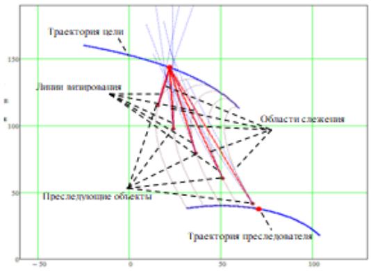 Figure 6: Dynamic Tracking Areas of Pursuing Objects Converting vectors
$\vec{V}_1$ and $\vec{V}_2$ from the coordinate system $\left( \begin{array}{ccc} \vec{E}_1 & \vec{G}_i & \vec{E}_2 \end{array} \right)$ to the world $\left( \begin{array}{cc}\vec{H}_1 & \vec{H}_2 \end{array} \right)$ it looks like this:
$$
\vec{v}_1 = \left[ \vec{V}_1 \cdot \vec{h}_1 \atop \vec{V}_1 \cdot \vec{h}_2 \right] + \vec{G}_i, \vec{v}_2 = \left[ \vec{V}_2 \cdot \vec{h}_1 \atop \vec{V}_2 \cdot \vec{h}_2 \right] + \vec{G}_i, \vec{h}_1 = \left[ \vec{H}_1 \cdot \vec{E}_1 \atop \vec{H}_1 \cdot \vec{E}_2 \right], \vec{h}_2 = \left[ \vec{H}_2 \cdot \vec{E}_1 \atop \vec{H}_2 \cdot \vec{E}_2 \right], \vec{H}_1 = \left[ \begin{array}{l} 1 \\0 \end{array} \right], \vec{H}_2 = \left[ \begin{array}{l} 0 \\1 \end{array} \right].
$$
Figure 6 shows how the tracking areas of the pursuing objects are formed, Figure 6 is supplemented with an animated image [17]. In Figure 5, the pursuing objects catch up with the target by the chase method without changing behavior, depending on whether the target enters the tracking area. Tracking areas are displayed for each object. The lines of sight connecting the pursuing object with the target are also displayed. Consider the behavior of the pursuing object.
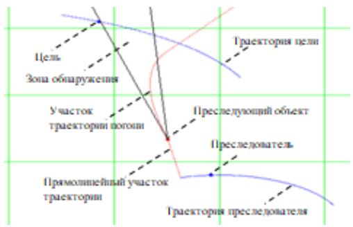 Figure 7: The Target is Out of the Detection Zone
Figure 7 shows that if at some point in time the target does not enter the detection area, then the pursuing object moves in a straight line. If the target has entered the detection area, then the behavior of the pursuing object corresponds to the chase method. Figure 7 is supplemented with an animated image [18].
## IV. RESULTS
In modeling the process of group pursuit, the method of chasing objects starting perpendicular to the pursuer's trajectory is used. In the model described in the article, nothing prevents us from replacing the chase method with the parallel approach method for catching up objects. And nothing prevents us from replacing the descent perpendicular to the pursuer's trajectory is replaced by a tangent descent.
- Based on the results of the research presented in this article, modeling was performed in a rectangular area $[-60:130] \times [0:190]$, measurement in meters.
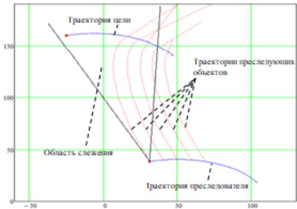 Figure 8: Group Pursuing Model
Figure 8 shows the simulation results. The pursuer's speed is $20 \, \text{m/s}$, the target's speed is $20 \, \text{m/s}$. The speed of the pursuing objects is $60 \, \text{m/s}$. The curvature radius of the pursuer's trajectory should not be less than $50 \, \text{m}$. The target pursues by parallel approach, the curvature radius of the trajectories of the pursuing objects should not be less than $10 \, \text{m}$. The pursuing objects descend perpendicularly from the pursuer's trajectory at regular intervals of $0.02 \, \text{s}$. Figure 8 is supplemented with an animated image [19], where it will be possible to get acquainted with the results of such a group pursuit.
In the simulation presented in this article, all objects released from the trajectory reach the target. This result depends on several factors: on the angle of the detection zone, on the speed of the pursuing objects, on the value of the minimum curvature radius of the object trajectories.
In the model considered in the article, it is found out that in order to avoid being hit by a pursuing object, it is necessary to leave the detection area. The closer the pursuing object is, the fewer iteration steps the target needs to take in order to leave the detection area.
For the pursuing object, the guaranteed result of catching the target would be to switch to the movement direction, the vector of which would be co-directed to the vector of the target's speed. Based on the results of the program, a certificate of state registration of the computer program No. 2020614336 "Modeling of trajectories from the pursuer to the target with curvature restrictions and with specified boundary conditions" was issued [20].
## V. CONCLUSIONS
The results obtained in this article could be used in the development of unmanned aerial vehicles with autonomous control, equipped with elements of artificial intelligence. It is also possible to use the results with satellite guidance of barrage projectiles.
Generating HTML Viewer...
References
17 Cites in Article
R Isaacs (1967). Differential games.
N Krasovsky,A Subbotin (1974). Positional Differential Games/ M.
L Petrosyan (1977). Examples of differential games of pursuit.
A Bannikov (2013). A non-stationary problem of group pursuit.
M Khachumov (2015). 2. Research in Problem Solving, Judgment, and Decision Making.
M Khachumov (2016). The problem of target pursuit by a group of unmanned flight vehicles.
T Abramyants,E Maslov,V Yakhno (2008). Evasion of multiple target in three-dimensional space.
P Gusyatnikov (1976). The escape of one nonlinear object from several more inert pursuers // Differential Equations.
P Gusyatnikov (1978). A differential evasion game.
P Gusyatnikov (1978). Differential escape game // Cybernetics.
A Bogdanov,A Filonov,A Kovalev,A Kuchin,I Lyutikov (2014). Methods of homing fighters and air-to-air missiles to a group air target/ Monograph.
S Nikitchenko,A Bassauer (2018). Simulation model of the mutual pursuit problem. // Regional Informatics and information security.
L Kuzmina,Y Osipov (2013). Calculation of the path lengthin the pursuit problem.
Jamir Fernandes (2024). Ensinando Matemática com a utilização do App Inventor 2.
(2016). LAS VEGAS SANDS CORP., a Nevada corporation, Plaintiff, v. UKNOWN REGISTRANTS OF www.wn0000.com, www.wn1111.com, www.wn2222.com, www.wn3333.com, www.wn4444.com, www.wn5555.com, www.wn6666.com, www.wn7777.com, www.wn8888.com, www.wn9999.com, www.112211.com, www.4456888.com, www.4489888.com, www.001148.com, and www.2289888.com, Defendants..
(2016). LAS VEGAS SANDS CORP., a Nevada corporation, Plaintiff, v. UKNOWN REGISTRANTS OF www.wn0000.com, www.wn1111.com, www.wn2222.com, www.wn3333.com, www.wn4444.com, www.wn5555.com, www.wn6666.com, www.wn7777.com, www.wn8888.com, www.wn9999.com, www.112211.com, www.4456888.com, www.4489888.com, www.001148.com, and www.2289888.com, Defendants..
(null). Video 9. Simulation results when target LEC is varied..
No ethics committee approval was required for this article type.
Data Availability
Not applicable for this article.
How to Cite This Article
Dr. A a Dubanov. 2026. \u201cGroup Pursuit on a Plane with Modeling Detection Area\u201d. Global Journal of Computer Science and Technology - H: Information & Technology GJCST-H Volume 22 (GJCST Volume 22 Issue H2).
Explore published articles in an immersive Augmented Reality environment. Our platform converts research papers into interactive 3D books, allowing readers to view and interact with content using AR and VR compatible devices.
Your published article is automatically converted into a realistic 3D book. Flip through pages and read research papers in a more engaging and interactive format.
Our website is actively being updated, and changes may occur frequently. Please clear your browser cache if needed. For feedback or error reporting, please email [email protected]
Thank you for connecting with us. We will respond to you shortly.