

I. INTRODUCTION
As GSM technology continues to advance with extremely remarkable features especially in data evolution aspects like LTE and 5G, the need to provide proper and effective interfaces between those features and lower evolutions like Global System for Mobile (GSM) and Universal Mobile Telecommunications System (UMTS) which support voice is indeed a great necessity to ensure uninterrupted continuous of services [4]. One of the most remarkable features of the 3G network is their integration with 2G networks. The current deployment of CS networks provides enabling interoperability and flexibility in handling handovers to allow uninterrupted continues of services.
The Wireless Local Area Network (WLAN) coverage on one hand provides an extra coverage in the low signal strength region . When a User Equipment (UE) establishes a call while in one UTRAN Registration Area (URA) and moving to another URA, in the handover region, the UE measures and compares the signaling received from the new cell detected through cell reselection (IRAT reselection) processes and hence attempts to make a successful handover provided the cell it camps on (serving cell) has a neighboring relations with the best detected or measured cell and that minimum Ec/lo and RSCP are met . If this attempt of handover fails it can then lead of a possible call drop.
This document aims to meet the requirements by on-site engineers on solving handover and call drop problems and the optimization methodology required for evaluating network handover and call drop performance, testing and troubleshooting methods.
This paper is organized as follows: The Section I above describes a brief introduction of the concepts of handover and call drop being closely related. Section II represent the flow chart clearly indicating the necessary steps in detecting, evaluation, analysis and implementation of call drop and handover challenges. Section III represents the design and implementation of Drive Test (DT) procedure and optimization systems. Section IV aims at network optimization in handover success and call drop rates, detailing the specific network operation flow. In addition, to analyze common problems during network optimization; and finally the conclusions and references in the last Section V
II. DRIVE TEST (CALL QUALITY TEST) OPTIMIZATION FLOW
Drive Test and Call Quality Test are important to network evaluation and optimization. Drive Test and Call Quality KPIs act as standards for verifying networks. Overall, Drive Test helps to know the entire coverage, to locate cells with missing neighbor and to locate cross-cell coverage. Hard Handover and inter-RAT (Radio Access Technology) handover are used in coverage solutions for special scenarios in which Call Quality Test is proper. In this section we will briefly describe the Drive Test and Call Qaulity Test optimization flow in terms of SHO (Soft handover), HHO (Hard handover)u and inter-RAT handovers.
While Inter-RAT handover fails are due to incomplete configuration data, ping-pong reselection, attention should be particularly paid on the data configurations such as RNC (Radio Network Controller) parameters like MCC (Mobile Country Code), MNC (Mobile Network Code), LAC (Local Area Code), BCC (Base station Color Code), etc.
Since handover failures are hardly due to data configurations errors or mismatch as the errors in these configurations most often leads to a related alarms usually displayed on the monitoring tool. Therefore, this section will focus on SHO to describe the optimization flow which might not be seen on the monitoring tool except for a drive test collected data on-site.
The flowchart of the proposed Soft Handover Drive Test detection and analysis is shown in Fig: 2.1 below. The sequence of events are explained below:
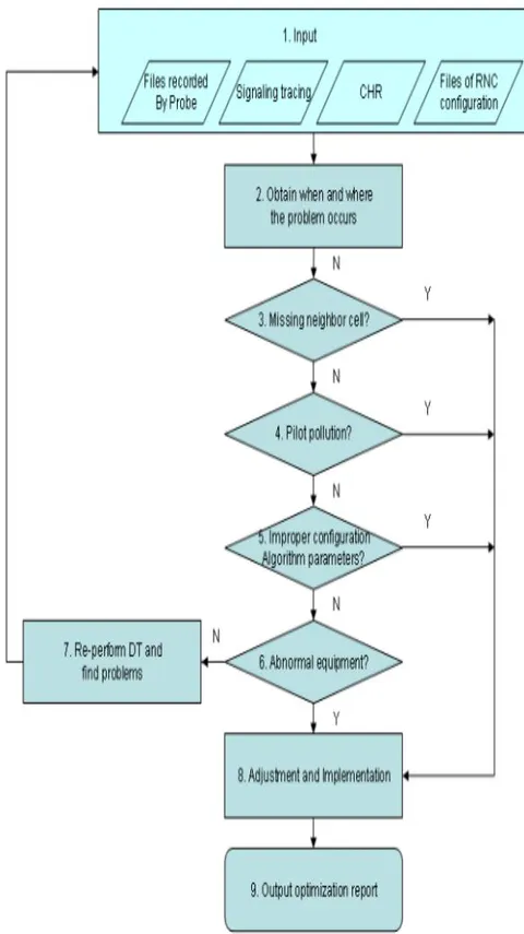
a) Inputting Analysis Data
In detecting and evaluating handover and call drop problems, a drive test is always a necessity to collect data, understand related signaling trace, RNC CHR and RNC MML Script. During the test, SHO-caused call drop might occur or SHO might fail, this spot is to be recorded and the time of occurrence of the problem also be noted for further location and analysis.
b) Missing Neighbor Cell
During the early optimization, a premature guess would be a call drop is usually due to missing neighbors. For intra-frequency neighbor cells, the following methods should be used to confirm intra-frequency missing neighbor cell.
√ Check the active set Ec/lo recorded by UE before call drop and Best Server Ec/lo recorded by scanner. Check whether the Best Server scramble recorded by Scanner is in the neighbor cell list of intra-frequency measurement control before call drop. The cause might be intra-frequency missing neighbor cell if all the following conditions are met:
The Ec/lo recorded by UE is bad
The Best Server Ec/lo is good
No Best Server scramble is in the neighbor cell list of measurements control.
√ If the UE reconnects to the network immediately after a call drop and the scramble of the cell that the UE camps on is different from that upon call drop, then missing neighbor cell is probable. Confirm it by measurement control (search the messages back from call drop for the latest intra-frequency measurement control message. Also check the neighbor cell list of this measurement control message) As neighboring relations between cells of a network are very important to allow continues use of services, and since missing neighbor cell causes call drop, redundant neighbor cells also impacts network performance and increases the consumption of UE intra-frequency measurement. If this problem becomes critically serious, the necessary cells cannot be listed.
c) Pilot Pollution
Another factor affecting call drop and handover failure is pilot pollution. Pilot pollution usually exist at a point where excessive strong pilots exists, but no one is strong enough to be the primary pilot.
By definition, when setting rules for judging pilot pollution, confirm the following content:
√ Definition of strong pilot: whether a pilot is strong depends on the absolute strength of the pilot, which is measured by Received Signal Code Power (RSCP). If the pilot RSCP is greater than a threshold, the pilot is a strong pilot, namely:
√ Definition of "excessive": here the pilot number is the judgemental criteria. If the pilot number is more than a threshold, the pilots at a point are excessive, namely:
√ Definition of "No best server strong enough": to compare the existence of the best stronger server, the judgement criteria is the relative strength of multiple pilots. If the strength difference of the strongest pilot and the number of the strong pilot is smaller than a threshold, then no best server strong enough exists at that point, namely:
Following the descriptions, pilot pollution exists if the following conditions are met:
√ The number of pilots satisfying CPICH_RSCP > is more than .
Set , , and , the judgement standards for pilot pollution are:
- The number of pilots satisfying CPICH_RSCP > -95dBm is greater than 3.
To eliminate problems of call drop and handover issues, the following two problems must be solved by adjusting algorithm parameters.
√ Delay handover
By the signaling flow for CS serices, the UE fails to receive active set update command. After the UE reports measurement message, the Ec/lo of original cell signals decrease sharply. When the RNC sends active set update message, the UE powers off the transmitter due to asynchronization. The UE cannot receive active set update message. For PS services, the UE might fail to receive active set update message or perform TRB (Traffic Radio Bearer) reset before handover. The delayed handover might be one of the following:
Turning corner effect: The Ec/Io of the original cell decreases sharply, and that of the target cell increases greatly in response (an overly high value may appear).
Needlepoint effect: The Ec/lo of original cell decreases sharply before it increases and the Ec/lo of target cell increase sharply for a short time.
According to the signaling flow, the UE reports the 1a and 1c measurement reports of neighbor cells before a call drop. Then the RNC receives the event and sends the active set update, which the UE fails to receive.
√ Ping-pong Handover
Ping-pong handover is of the two forms below
Since the best server changes frequently, two or more cells continuously alternate to be the best server. Also, since the period for each cell to be best server is short, the RSCP of the best server is strong.
Multiple cells exist with little difference of abnormal RSCP, the Ec/Io for each cell is bad and therefore, no primary pilot cell exists.
Referencing the signaling flow, when a cell is deleted, the 1a event is immediately reported. Consequently, the UE fails because it cannot receive the active set update command.
e) Abnormal Equipment
The failures or abnormal functionalities can always be troubleshooted starting with the alarm console for abnorma alarms. Meanwhile the trace messages are to be analyze, locate the SHO problem by checking the failure message.
f) Reperforming Drive Test and Locating Problems
If the problem is not due to any of the previous causes, perform DT again and collect DT data and supplemet data from problem analysis.
After confirming the cause to the problem, adjust the network by using the following pertinent methods:
For handover problems caused by pilot pollution, adjust engineering parameters of antenna so that a best server forms around the antenna. Also, adjust engineering parameters of other antennas so that signals from other antennas become weaker and the number of pilots drop. In the event that the aforementioned suggestions fail, construct a new site to cover this area if the conditions permit or combine the two cells as one if the interference is from two sectors of the same NodeB.
For abnormal equipment, consult customer service engineer for abnormal equipment and transport layer on alarms console. If alarms are present on alarm console, cooperate with customer service engineers
For call drop caused by delayed handover, adjust antennas to expand the handover areas, set the handover parameters of 1a event or increase CIO (Cell Independent Offset) to enable handover to occur in advance.
For needle effect or turning corner effect, setting CIO to 5 dB is proper, but this increases handover ratio.
For call drop caused by Ping-pong handover, adjust the antenna to form a best server or reduce Ping-pong handover by setting the handover parameter of 1B event, the 1B event threshold, 1B hysteresis and 1B delay trigger time.
III. HARDWARE, DESIGN AND IMPLEMENTATION OF DRIVE TEST USING GENEX
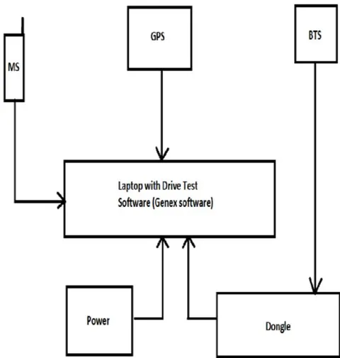
A laptop with drive test software and GPS connection capability, data cables and multi-connector port.
A GPS tracker,
A Drive test mobile phone (e.g. Huawei MT7-L09)
An inverter
a) Laptop
The Genex software is installed in the laptop as a tool to collect visualized data being collected, the route taken during the drive test and records the data to be analyzed with another software called "Genex Assistant".
b) GPS Tool
The GPS tracker keeps tabsof the movemets of the drive test car on a map so as to cover the target route
c) Drive Test mobile phone
One of the most important tools is the MS as the purpose of the drive test is to understand its behaviour in idle and connected modes. The tools make a capture of the events the MS is going through during the drive test like attempted calls, successful and unsuccessful calls, handover success rates, call drop rates, while also measuring the thresholds sets (coverage, offset, etc) for minimum handovers.
d) The Inverter
The inverter used here will be a DC to AC inverter. Its purpose is to keep the laptop charged during the drive test as it might be discharged during the drive test when the target drive test is not completed leading to either stop the drive test or lossage of data when it turns off by its completely discharged.
IV. NETWORK OPTIMIZATION OF CALL DROP RATE AND HANDOVER
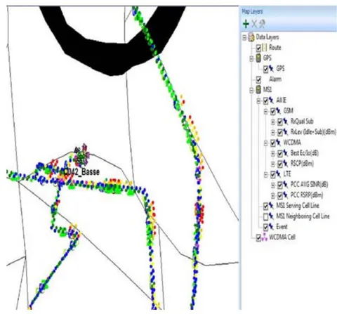
The call drop point is related to signaling flow before call drop. The call drop can also be seen during the drive test analysis on a Genex Assistant tool like shown in Figure 4.1
a) Analysis
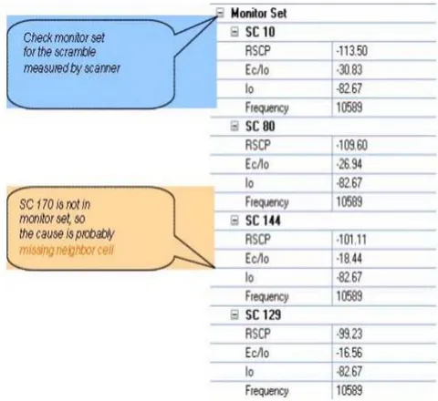
Check the pilot test data from UE and scanner at call drop points. Then check the scrambles recorded by UE active set and scanner before call drop. In the analysis, we realized the measurement result of UE active set and scanner is inconsistent as the scanner has a scrambling code not existing in the UE active set. The cause might be due to missing neighbor cell or delayed handover as the scrambling code does not even exist in the UE monitor set as shwon in the figure 4.2 below.
If only the UE recorded information during test, without scanner information, then the call drop due to missing neighbor cell is to be confirmed using the following methods:
√ Confirm the scrambles of all cells in active set and the scrambles of cells in monitor set measured by UE before a call drop.
√ Compare the scramble information of the cell where the UE camps on after reselection, after a call drop and the scrambles in UE active set and monitor set before a call drop. If the former scramble is not in the scramble list of active and monitor set before call drop, then the call drop is probably due to missing neighbor cell
√ Check the neighbor cell list. This applies for solving call drop due to missing neighbor cell on site.
b) Solution
When a call drop is as a result of missing neighbor cell, then the neighbor cell should be added. This is because the RNC (Radio Network Controller) updates measurement control according to the best cell which is obtainable by searching for intra-frequency measurement report with 1D event before measurement control is sent.
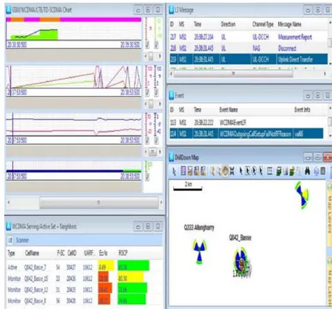
In the post drive test, after adding the missing neighbors, another call drop was recorded but this time it was not due to RF (Radio Frequency) reason. The scrambles of all cells in active set and the scrambles of cells in monitor set measured by UE before and after a call drop are indeed neighbor cells as seen in figure 4.3
V. CONCLUSIONS
In this paper, we have seen that handover is actually closely related to call drop. Hence, call drop minimization techniques employed here to reduce the number of call drops and enhance handover in mobile cellular networks are indeed efficient and reliable. One should not only limit to these techniques as there are many reasons leading to call drops and handover failures such a transmission failures, faulty channels, etc. However, for an optimization engineer, a drive test is always an necessary to confirm the cause of call drops or degradation in handovers.