
I. INTRODUCTION
Colleagues in the chemical community know that the 2019 Nobel Prize in Chemistry is awarded to three scientists who have made great contributions to the research and development of lithium batteries. They are Professor John. Good enough in the University of Texas at Austin, Professor M Stanley Witt in gham in State University of New York, Binghamton, USA, and Professor Akira Yoshino in Nagoya University, Japan. This event itself shows that the invention, development and application of lithium-ion batteries are of great significance in science and technology, social progress and the improvement of human quality of life in today's world.
In the past 20 years, due to the development of mobile phones, electric bicycles and new energy vehicles, countries all over the world attach great importance to the research, development and application of renewable energy, and our country also attaches great importance to the research, development, industrialization and application of lithium-ion batteries.
After retiring in August 1999, from 2003 to 2011, he was invited to return to the Shanghai Institute of Microsystems and Information Technology (former
Metallurgy), Chinese Academy of Sciences, which worked for 26 years (1963-1988). Under the leadership of Professor Xia Baojia, he participated in the study of X-ray diffraction characterization of active materials and the mechanism of charge-discharge, cycle and storage of secondary batteries [including Ni/MH, graphite/Li(Ni,Co,Mn)2 and graphite/LiFePO4 batteries], and published a series of papers.
In 2011, he left the research group due to his wife's health, but did not give up this meaningful work. Yang Chuanzheng, Lou Yuwan, Zhang Jian, Xie Xiaohua and Xia Baojia published the Chinese version of the monograph «Material characterization and electrode process Mechanism of green Secondary batteries» [31](Science Press, 2011). In 2022, the English version of «Materials and Working Mechanisms of Secondary Batteries» (Springer and Science Press in Beijing, 2022) [32] was published(See Attached). These research results belong to the research group. Not only five authors, but also many graduate students have made important contributions. Li Xiao-Feng, Li Jia, Liu Hui, Yan Jian, Liu Hao-Han, Li Yu-Xia and Wang Bao-Guo are worth mentioning. This is the result of the interdisciplinary study of electrochemistry, chemical power supply experts working closely with material physics and X-ray analysis experts.
This time, at the invitation of the Global Journal of Science Frontier Research, I would like to introduce the relevant research results to readers with two summary papers, so as to communicate and learn from their international counterparts. one is "The Leave-intercalation theory and conductive mechanism during charge-discharge process for secondary battery", the other is "Study on the mechanism of cycle and storage process of lithium-ion battery".
There has been a classic introduction to how the battery works. However, there are few studies on the chemical and physical behavior and conductive physical mechanism in the process of charge and discharge.
Summarize the relevant experimental results, this paper comprehensively introduces a series of important results of X-ray diffraction studies on the charge and discharge processes of -Ni(OH) , graphite/LiMeO and graphite/LiFePO batteries, including the de-intercalation theory of the source of conductive ions in the process of charge and discharge, and then clarifies the physical mechanism of the conductivity of secondary batteries.
II. EXPERIMENTAL STUDY ON CHARGE AND DISCHARGE PROCESS OF HYDROGEN-NICKEL BATTERY
a) Phase transition during charge and discharge of hydrogen-nickel battery In 1966, Bode et al. [1] described the working principle of the battery as follows:
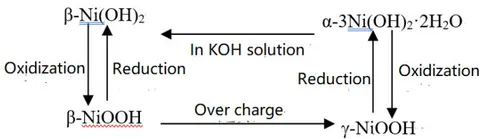
The working principle is written as the following chemical reaction formula [2]. Positive pole negative pole.
The above description of how the battery works has been written into teaching books and academic monographs [3].
The above tells us that the chemical mechanism of conducting electricity is:
(1) The phase transition occurs during charging, and the ion is supplied by this phase transition. (2) The transition of hydrogen (hydride) occurs during the charging process. (3) The above two phase transitions are completely reversible in the process of charge and discharge.
The above conductive mechanism can be called phase transition theory. It can also be seen from the above that under the action of electric field, the driving force of phase transition is oxidation, and the driving force of is reduction. It can be seen that oxidation-reduction is for Ni, and oxidation and reduction occur on the positive electrode and discharge respectively, which is not accordance with the principle that oxidation and reduction occur on the positive and negative electrodes respectively during charging (or discharging).
In 1999, Xing Zhengliang, Li Guoxun and Wang Chaoqun reported the results of charge-discharge insitu XRD observations. The diffraction pattern of 1c charge for was identified as the coexistence of -NiOOH and -NiOOH. This seems to give the experimental evidence of the conductive phase transition theory of MH/Ni battery. However, the experimental evidence of the coexistence of -Ni
-NiOOH or pure -NiOOH phase before fully charged was not obtained. Therefore, it is very necessary to study the physical phenomena and physical conductive mechanism of charge-discharge process in detail, and it also has theoretical and practical significance.
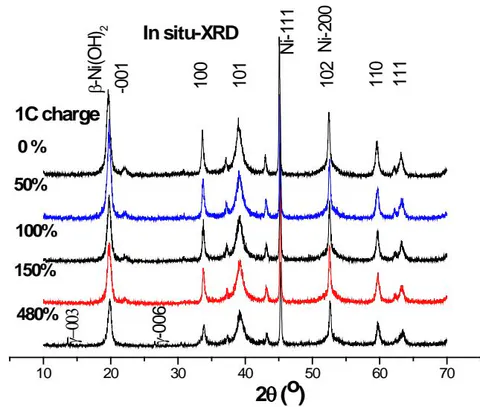
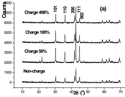
b) In situ XRD study of -Ni(OH) on Nickel electrode during charging In this study, the charge in situ observation was carried out by using the charge-discharge in-situ XRD device (patented product) provided by Rigaku Company in Japan. 1C the diffraction patterns of several stages of charging are shown in figure 1. We can see that in the characteristic diffraction spectrum of after 1C charging 50,100,150,480%, only when 1C is 480%, not only the characteristic diffraction pattern of , but also the 003 and 006 diffraction peaks of are observed. The results show that (1) the charge depth of the observed surface is much smaller than that of the interior of the battery, that is, there is a serious hysteresis effect on the surface; (2) in the case of overcharge, coexists rather than coexist.
c) Quasi-dynamic study of positive active material during charge and discharge of MH/Ni battery
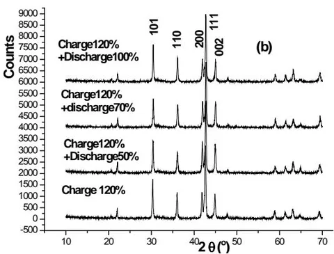
The so-called quasi-dynamic is sampling at different stages of charging and discharging, in other words, some stages of charging or discharging of the battery (original, several intermediate and final states) stopped abruptly, and then the battery was dissected and the positive and negative active materials were obtained as samples for XRD research and analysis.
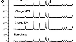
Figure 2 (a) shows the diffraction pattern of several charging stages.
i. Phase structure change of during charge and discharge of MH/Ni battery
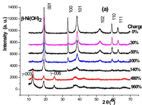
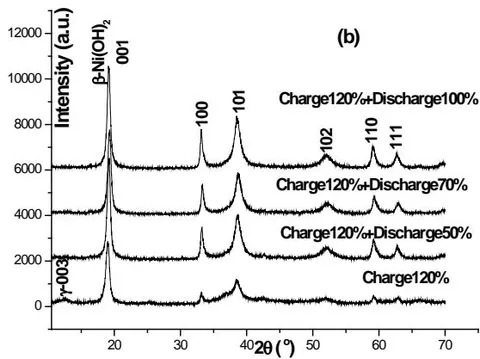
Know from figure 2 (a)
(1) When the charging depth is , the positive active material still belongs to . (2) A small amount of -NiOOH is not precipitated until the charging depth reaches and . (3) The content of -NiOOH phase increases with the increase of charging depth.
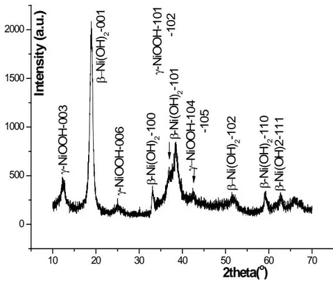
Now let's analyze the 0.2C charging and XRD patterns. The result of charging is shown in figure 3.It can be seen that the positive active material with charge at belongs to the mixture of and , rather than a mixture of and . Therefore, The pattern of 1C charge for 3 hours ( ) was identified by Xing Zhengliang, Li Guoxun and Wang Chaoqun as the mixture of -NiOOH and -NiOOH, that is worth discussing.
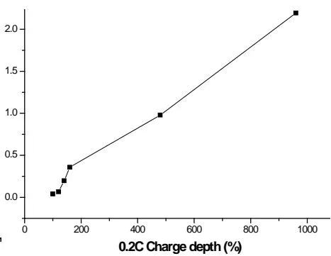
From the relationship (see Fig.4) between , and overcharge percentage, it can be seen that the content of -NiOOH phase increases with the increase of overcharge percentage.
belongs to hexagonal structure, P-3m (No.164) space group. There are 1 molecule, 5 atoms, namely 1 Ni atom, 2 oxygen atoms and 2 hydrogen atoms in the unit cell. The chemical bond between Ni and O is stronger, while that between H and O is much weaker. When there is no stacking disorder, the Ni-O layer presses ABAB.... Stacking in sequence.
The experimental results in sections 2.2 and 2.1 have fully proved that there is no phase transition from to during the charging process of MH/Ni battery. The hydrogen ion is not provided by this phase transition. The lattice parameters a and c of decrease with the charging process, which indicates that the hydrogen atom leaves the lattice position of and stay a vacancy, which leads to the lattice distortion of and the increase of stacking fault probability. Only when there are enough hydrogen atoms leaving the -Ni(OH)2 lattice for Ni: O: H to fall from 1:2:2 to 1:2:1 does NiOOH precipitate from -Ni(OH)2.
There is now a saying that when -NiOOH, the volume shrinks by , and when -NOOH, the volume shrinks by . This seems to be wrong. When -Ni -NOOH, the cell volume increases by (see Table 1).
| Compound | \beta\text{-Ni(OH)}_2 | \beta\text{-NiOOH} | \gamma\text{-NiOOH} |
|---|---|---|---|
| Structure system | Hexagonal | Hexagonal | Hexagonal |
| PDF card No. | 03-0177 | 06-0141 | 06-0075 |
| Valence state of Ni | Ni^{+2} | Ni^{+3} | Ni^{+3} |
| a (\AA) | 3.126 | 2.81 | 2.828 |
| c (\AA) | 4.605 | 4.84 | 20.569 |
| V (\AA^3) | 38.97 | 33.10 | 141.45 |
| The rate of increase of cell volume (\%) | 0.00 | -15.07 | +262.98 |
| Density (g/cm^3) | 3.948 | 4.62 | 3.890 |
| Number of molecules/unit cell | 1 | 1 | 4 |
| V(\AA^3)/ molecule | 38.97 | 33.10 | 35.36 |
| The rate of change in the volume occupied by a molecule (\%) | 0.0 | -15.0 | -9.3 |
More reasonably, the change in the volume of each molecule in the unit cell should be taken into account. In this way, the cell volume of each molecule is reduced by at and only at , as shown in the last row of table 4. It can be seen that it is more reasonable to have transition rather than transition phase transition.
The XRD patterns of several stages in the discharge state are shown in figure 2 (b). We can see that -NiOOH has been decomposed, and the phase structure of has not changed, but their fine structure has changed.
ii. -Ni(OH) fine structure [7, 11, 12]
The Refine in the Jade program has been used to determine the peak position and HWHM. The data were processed according to the method of reference [8, 9]. The lattice parameters a and c, the average grain size , the micro-strain and the total stacking fault probability of -Ni are calculated.
The changing trends in the charge-discharge process are summarized in Table 2.
| Parameter of fine structure | Charge process | Discharge process | |
|---|---|---|---|
| Lattice parameter | a | a decrease with the increase of charging depth. | It is roughly opposite to the charging process, but it is not completely reversible. |
| Lattice parameter | c | c Begin to decrease, then increase | |
| D_average | It thinning with the deepening of the charge and discharge process. | ||
| \varepsilon_{average} | With the deepening of the charge and discharge process, it begins to increase, and then becomes smaller. | ||
| (f_D+f_T) | With the deepening of the charging process, it begins to increase slowly, and then increases faster. | ||
d) Quasi-Dynamic study of negative electrode active material during charge-discharge process
The XRD spectrum of the negative electrode active material AB5 in several stages of charge and discharge is shown in figure 5. On the whole, the structure of alloy has no obvious change during charging, but the fine structure and microstructure also change. The changing trend with the charge-discharge process is summarized in Table 3. It can be seen that both an and c increase with the increase of charging depth, and the micro-strain also increases with the increase of charging depth. The discharge situation is just the opposite, but it returns to the original state, which indicates that there is some irreversibility in the charge-discharge process.
alloy during charge-discharge process
| Parameter of fine structure | Charge process | Discharge process | |
|---|---|---|---|
| Lattice parameter | a | Increase with the deepening of the charging process | It is roughly opposite to the charging process, but it is not completely reversible. |
| c | Increase with the deep of the charging process | ||
| Micro-strain \varepsilon | Increase with the deep of the charging process | ||
III. EXPERIMENTAL STUDY ON CHARGE AND DISCHARGE PROCESS OF 2H-GRAPHITE/LIME BATTERY
Lithium-ion battery is a new generation of green high-energy battery developed in the early 1990s, which has the characteristics of high energy density, high working voltage, long cycle life and low self-discharge rate, and has been widely used. It will become the preferred battery for electric vehicles and hybrid vehicles. As far as positive active materials are concerned, there are mainly four types of positive active materials: , Li (Ni, Co)O2, Li (Ni, Co, Mn)O2 and , but the negative active materials are all 2H-graphite with hexagonal structure, so there are various systems of 2H-graphite/LiCoO2, 2H-graphite/ Li(Ni,Co) O2, 2H-graphite/Li(Ni,Co,Mn) O2 and 2H-graphite/ . Moreover, there are different proportions in the binary or ternary systems of and . However, , and have the same crystal structure, so they can be written as general .
a) Structural evolution of positive active materials during charge-discharge of 2H-graphite/LiMeO battery In 1992, Reimers and Dahn [14] used an on-line (in situ) X-ray diffraction device to find that when is in the charging process of , due to lattice distortion, O-Li-O-Co-O-O., ABCABC... The rhombohedral structure of the stack is transformed into a monoclinic structure; Amatucci et al. (1996) [15] considered that the positive terminal of the battery at full charge is , which has a hexagonal structure. Yang and MeBreen et al. [16,17] studied the phase transition of during charging by means of on-line synchrotron radiation X-ray diffraction ( ). It is concluded that changes into monoclinic M2 phase at , and from hexagonal phase H2 of -type to O1A phase of -type at , which belongs to P63mc space group. Finally, it becomes O1 phase, which is . However, these studies only focus on the phase transition of materials during battery charging, and do not involve the changes of fine structure and microstructure; at the same time, they do not systematically study the fine structure changes of positive and negative active materials in the process of charge and discharge from the point of view of chemical physics. Therefore, in order to deeply understand the structural evolution of electrode materials in the actual battery operation process and explore the working mechanism of electrode materials in the real battery system, this section introduces the use of X-ray diffraction to study the crystal structure and microstructure changes of graphite/LiCoO and graphite/Li(Ni Co Mn )O lithium-ion batteries during charge and discharge.
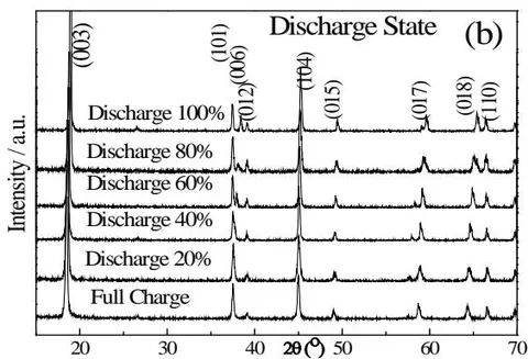
The XRD patterns of the cathode active material at different stages of charge and discharge are shown in figure 6. As can be seen from the figure, in the battery charging process, the change of the (006) peak in the cathode material XRD pattern is the most significant. At the initial stage of battery charging (10% charging), it splits at first, then moves to a low angle as the battery charge state continues to increase, and finally disappears; while other diffraction peaks have no other obvious changes except a small offset.
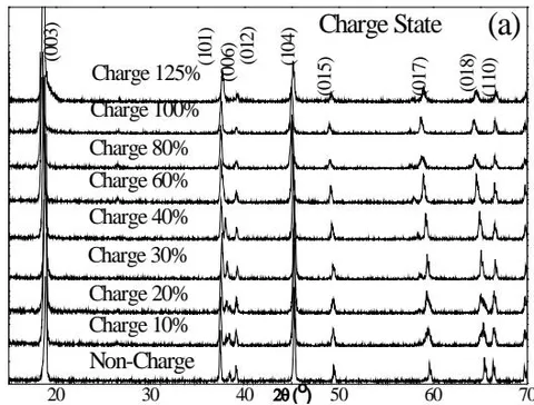
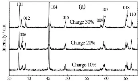
components. As can be seen from figure 7, from the battery charge to , in the spectrum (006), The four diffraction peaks of (015), (107) and (018) were all split into two peaks. At the same time, it was found that the intensity of the low angle peak (left peak) was lower than that of the high angle peak (right peak) after the split of each peak (006, 107, 018) at the initial charging stage (10% charging).
As the cell continues to charge (to ), the intensity of the low-angle peak increases, the intensity of the high-angle peak weakens, and the intensity of the two peaks is reversed.
The lattice parameters of the two peaks are calculated as two independent phases: when the battery is charged at , the corresponding low-angle peak.
The lattice parameters of the high-angle peak are asides 2.8114, 14.1670, and the high-angle peaks are 2.8104, 14.0983, respectively. It can be seen that the lattice parameters of the two phases are different, but from the characteristic peak, both phases are still phase.
The above analysis results can be explained as follows: at the initial stage of battery charging (up to ), the lattice parameters of the material are changed due to the separation of Li from the lattice, and the lattice parameters of the unde-Li remain unchanged, so there are two phases, which is called the lithium-deficient phase; as the battery continues to charge, with the continuous removal of Li, the relative intensity of the two-phase characteristic peaks reverses, indicating that the content of the lithium-deficient phase increases and the content of the original phase decreases. This clearly shows that the de-Li of has a process from the surface of the electrode to the inner layer.
At the same time, as can be seen from figure 6 (a), when the battery is charged to or , the positive active material becomes single-phase again.
The data of the standard are roughly consistent, only the lines have some displacement; when the battery continues to charge to , , and , except for the disappearance of 006 lines, the other lines are still consistent with the data of the standard , and no new phase is generated. This is different from the report of MeBreen et al. The reasons for the disappearance of 006 lines are as follows:
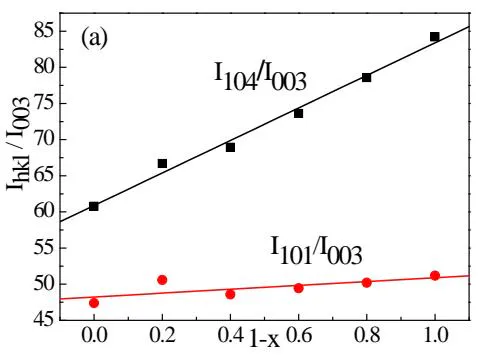
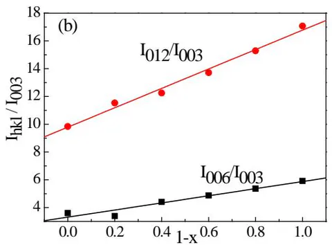
(1) The diffraction intensity of 006 decreases due to the removal of Li. For this reason, we use the Power Cell program to calculate the relative intensity of each diffraction line according to the model. The relationship between the relative intensity of each main diffraction line and 1-x is shown in figure 8. It can be seen that when is used, the diffraction intensity of 006 decreases very low and is not visible. (2) lit is possible that 006 overlaps with 101 or 012 due to the change of lattice parameters.
(3) The mixed arrangement of Li/Ni atoms may occur in 2H-graphite/Li battery during charge and discharge [17].
- Comparing figs. 8 (a) and (b), it can be seen that the structural change of the positive material during the discharge of the battery is basically the reverse process of charging.
b) Structural evolution of negative active materials 2H-graphite
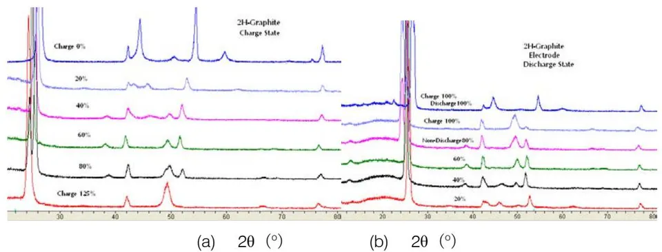
The XRD patterns of 2H-graphite/LiCoO lithium-ion battery with hexagonal graphite as negative active material during the charge and discharge process are shown in Fig.9(a) and (b) respectively. The results of the analysis are listed in Table 4.
| Charge state | Discharge state | |||
|---|---|---|---|---|
| charge (%) | Existing phase | discharge (%) | no discharge (%) | Existing phase |
| 0 | 2H-graphite | 100 | 0 | 2H- graphite 1+2H-graphite 2 |
| 10 | 2H- graphite 1+2H- graphite 2 | |||
| 20 | 2H- graphite | 80 | 20 | 2H-graphite1+2H-graphite 2 |
| 30 | 2H- graphite | |||
| 40 | 2H- graphite | 60 | 40 | 2H-graphite |
| 60 | 2H- graphite | 40 | 60 | 2H-graphite +LiC12 |
| 80 | LiC24 + LiC6 | 20 | 80 | LiC12 + LiC6 |
| 100 | LiC6 + Li2C2 + LiC12 + LiC24 | 0 | 100 | LiC6 + Li2C2 + LiC12 + 2H-graphite |
| 125 | LiC6 + Li2C2 | |||
As can be seen from figures 9 and Table 4, there is a gap between the hexagonal grids of carbon atoms embedded in the graphite lattice of Li atoms to form a solid solution, and then , , and are precipitated. As for when these compounds are precipitated, it is related to the system of lithium-ion battery and the ratio of positive and negative active materials.
IV. EXPERIMENTAL STUDY ON CHARGE DISCHARGE PROCESS OF 2H GRAPHITE/LIFEPO BATTERY
a) Phase identification of 2H-graphite/LiFePO battery during charge and discharge [23]
has become one of the most likely cathode active materials to replace lithium secondary battery [19]. This is because lithium secondary ion battery with lithium iron phosphate as cathode has the characteristics of high safety, long life, low cost and environment-friendly, so it has become the focus of development and research in the battery industry. At room temperature, the de-intercalation behavior of is actually a two-phase reaction process forming the two-phase interface between and
. Newman[20], Yamada[21] and Dodd[22] have systematically studied the phase transition during the charge-discharge process of . During charging, the lithium ion migrates from the FeO6 layers and enters the negative electrode through the electrolyte, resulting in the oxidation reaction of . In order to maintain the charge balance, the electron arrives at the negative electrode from the external circuit. The reduction reaction occurs during the discharge, and the discharge is opposite to the above-mentioned process. However, the oxidation-reduction occurs on the positive electrode and corresponds to charge-discharge respectively. That is:
is a typical electron-ion mixed conductor with a band gap of , low electronic conductivity at room temperature and low ionic conductivity at room temperature (about ). Therefore, in order to use as cathode material for lithium-ion battery, it is necessary to improve its electronic and ionic conductivity and improve its electrochemical interface properties.
Figure 10 shows the X-ray diffraction pattern of the positive plate at several stages of the charging (a) and discharging (b) process, and the Pnma orthogonal structure can be used to index and , represented by the letters T and H, respectively. It should be noted that with orthogonal structure [Pnma (No.62), 34-0134] can only be used for charging patterns,
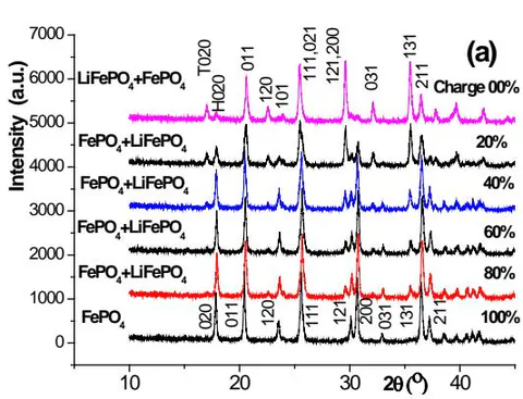
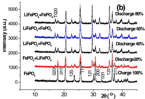
The of (No.63) or (No.180)] is indexed. It can be seen that there are and in the positive active material after the aforementioned formation, and the content of the former is more. With the increase of the charging depth, the gradually decreases and the gradually increases. When the charge reaches , there is still a trace of , and it is not all until the charge reaches .
From the diffraction pattern of several stages of the discharge process [figure 8 (b)], it can be seen that the positive electrode of the fully charged battery is composed of pure , and appears at discharge, and increases with the increase of discharge depth, until discharge, although it is dominated by , there is still a considerable amount of . Comparing the phase composition of the positive active material of discharge with that of the positive active material when charging , there is an obvious difference between them, which shows that the positive active material is not completely reversible or called asymmetry in the charge-discharge process, but it indicates that there is a change of in the charge-discharge process.
However, based on the synchrotron radiation online (in situ) XRD method, Shin, Chung and Min et al. [24] found that the asymmetry of structural change was not observed in carbon-coated during charge/discharge, and but the asymmetry became serious when the magnification factor increased to 2C and 10C.
b) Quantitative analysis of phase study on the hysteresis effect of discharge
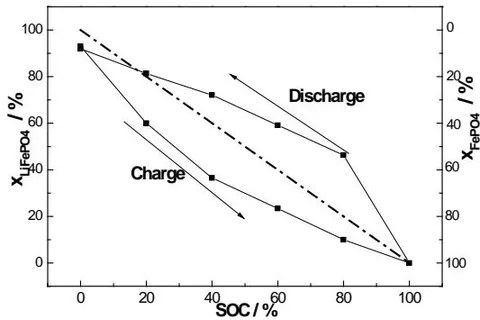
In order to further analyze the asymmetry of the phase transition of the positive active material during the charge and discharge of graphite/LiFePO battery, the relative contents of FePO and LiFePO in the positive active material at each stage of charge and discharge were quantitatively determined by Zervin's non-standard method [26: 27]. The results are shown in figure 11. As can be seen from figure 9, (1) even in , the positive active material is not entirely LiFePO phase, in which there is a small amount of FePO phase (calculated to be about ), which is due to the formation of inactive FePO shell during the first charge. (2) in the case of the same SOC, the content of LiFePO in the discharge state is more than that in the charge state, on the contrary, the FePO content in the discharge state is obviously low charge state, which obviously reveals that the asymmetry of charge and discharge is caused by the hysteresis effect of discharge.
c) The phase transition nature of [20] Both and belong to triphylite orthorhombic system and Pnma (No.62) space group, while FePO4 belongs to heterosite orthorhombic system and can only be indexed by (No.62) space group. The actual measured lattice parameters are:
| a(Å) | b(Å) | c(Å) | V(Å3) | (VT-VH)/VT | ||
| LiFePO4 | 6.0157 | 10.3915 | 4.7207 | 295.101 | 0.00% | |
| FePO4 | 5.8094 | 9.9222 | 4.8166 | 277.638 | -5.92% |
| a(Å) | b(Å) | c(Å) | V(Å3) | (VT-VH)/VT | ||
| LiFePO4 | 6.0157 | 10.3915 | 4.7207 | 295.101 | 0.00% | |
| FePO4 | 5.8094 | 9.9222 | 4.8166 | 277.638 | -5.92% |
Each unit cell of crystalline contains four molecules, namely, 4 Li atoms, 4 Fe atoms, 4 phosphorus atoms and 16 oxygen atoms, with a total of 28 atoms. The atomic position is as follows[25]:
| Li 4a | 0 | 0 | 0 |
| Fe 4c | 0.282 | 1/4 | -0.023 |
| P 4c | 0.095 | 1/4 | 0.418 |
| O1 4c | 0.107 | 1/4 | -0.268 |
| O2 4c | 0.460 | 1/4 | 0.208 |
| O3 8d | 0.165 | 0.043 | 0.288 |
| Li 4a | 0 | 0 | 0 |
| Fe 4c | 0.282 | 1/4 | -0.023 |
| P 4c | 0.095 | 1/4 | 0.418 |
| O1 4c | 0.107 | 1/4 | -0.268 |
| O2 4c | 0.460 | 1/4 | 0.208 |
| O3 8d | 0.165 | 0.043 | 0.288 |
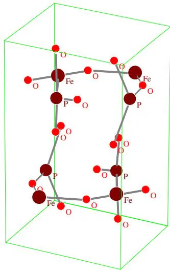
The unit cell also contains four molecules, namely, 4 Fe atoms, 4 phosphorus atoms, 16 oxygen atoms, a total of 24 atoms, and their atomic positions are as follows [26]
\begin{table}\begin{tr}\begin{td}\end{td}\begin{td}x\end{td}\begin{td}y\end{td}\begin{td}z\end{td}\end{tr}\begin{tr}\begin{td}Fe\end{td}\begin{td}4c\end{td}\begin{td}0.277\end{td}\begin{td}1/4\end{td}\begin{td}0.9449\end{td}\end{tr}\begin{tr}\begin{td}P\end{td}\begin{td}4c\end{td}\begin{td}0.0935\end{td}\begin{td}1/4\end{td}\begin{td}0.3983\end{td}\end{tr}\begin{tr}\begin{td}O1\end{td}\begin{td}4c\end{td}\begin{td}0.1167\end{td}\begin{td}1/4\end{td}\begin{td}0.7131\end{td}\end{tr}\begin{tr}\begin{td}O2\end{td}\begin{td}4c\end{td}\begin{td}0.4417\end{td}\begin{td}1/4\end{td}\begin{td}0.1614\end{td}\end{tr}\begin{tr}\begin{td}O3\end{td}\begin{td}8d\end{td}\begin{td}0.1684\end{td}\begin{td}0.0461\end{td}\begin{td}0.2513\end{td}\end{tr}\end{table}
| x | y | z | ||
| Fe | 4c | 0.277 | 1/4 | 0.9449 |
| P | 4c | 0.0935 | 1/4 | 0.3983 |
| O1 | 4c | 0.1167 | 1/4 | 0.7131 |
| O2 | 4c | 0.4417 | 1/4 | 0.1614 |
| O3 | 8d | 0.1684 | 0.0461 | 0.2513 |
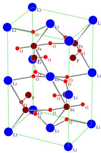
The crystal structure model and chemical combination of and are shown in figs. 12 and 13, respectively.
V. LEAVE-INTERCALATION THEORY DURING CHARGE/DISCHARGE PROCESS FOR SECONDARY BATTERY [29]
a) Comprehensive analysis
On the basis of the above research results, the de-intercalation theory of ionic conductivity of secondary battery and the de-intercalation behavior of positive and negative active materials are described from an overall point of view.
The following reactions do not occur at the positive electrode during the charging and discharging process of the hydrogen-nickel battery.
The following reactions occur at the positive electrode of 2H-graphite/LiCoO lithium-ion battery during charge and discharge.
The following reactions occur at the positive electrode of 2H-graphite/ lithium-ion battery during charge and discharge.
LiMeO_2\Leftrightarrow Li_{1-x}MeO_2+xLi^++xe^-\[\text{Me represent (Ni,Co,Mn)}\]The following reactions occur at the positive electrode of 2H-graphite/LiFePO4 lithium-ion battery during charge and discharge.
So people come to the conclusion that the conductive ions of the battery are provided by phase transition, which is called the phase transition theory of ionic conductivity.
After careful analysis, it is found that the oxidation reaction occurs at the positive electrode and the reduction reaction occurs at the positive electrode during discharge. In other words, the phase transition force during charging is oxidation reaction, and the driving force during discharge is reduction reaction, but this is not consistent with the following principle. that is, in the process of realizing the direct conversion of chemical energy into electric energy, the chemical power supply is in the process of directly converting chemical energy into electric energy. There must be two necessary conditions, one of which is that the process of losing electrons (oxidation) and obtaining electrons (reduction) in chemical reactions must be separated on positive and negative electrodes. Therefore, it is different from the general oxidation-reduction reaction.
Our experimental study found that: The above phase transition does not occur during the charging process of the hydrogen-nickel battery, and the following phase transition occurs only when the battery is fully charged and overcharged.
Although the following changes have taken place in 2H-graphite/LiCoO2 lithium-ion battery
However, the crystal structure of is the same as that of , and the latter stay a vacancy in the lattice position of Li. Similar changes have taken place in 2H-graphite/Li(Ni,Co,Mn)O lithium-ion batteries as follows
However, the crystal structures of and are also the same, and the latter stay a vacancy in the lattice position of Li.
The following changes occur during the charging process of 2H-graphite/LiFePO lithium-ion battery
However, the crystal structures of , and are the same, and the phase transition belongs to pseudo-structure phase transition. The latter two are only lack of Li and no Li in the lattice position of Li.
- Because of this, we put forward the de-intercalation theory of ionic conductivity of secondary battery, and clarify the conductive mechanism based on the de intercalation theory.
- However, the de-intercalation mechanisms of different electrode active materials in secondary batteries are different. The de-intercalation mechanisms of the electrode active materials involved in this paper are summarized as follows: b) The deintercalation mechanism of -Ni(OH)
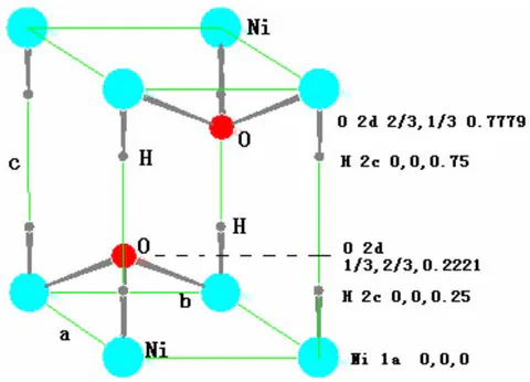
belongs to hexagonal structure, P3m1 (No.164) space group, there are one molecule in the unit cell, that is, one Ni atom, two oxygen atoms and two hydrogen atoms, a total of five atoms. Their crystallographic positions in the unit cell are as follows:
| Atom | position | x | y | z |
| Ni | 1a | 0 | 0 | 0 |
| H | 2c | 0 | 0 | ±1 |
| O | 2d | 1/3 | 2/3 | ±0 |
The crystal structure model and chemical bonding are shown in figure 16. As can be seen from the diagram, the chemical bond between Ni and O is stronger, while that between H and O is much weaker. When there is no stacking disorder, the Ni-O layer presses ABAB. The hydrogen is stacked sequentially, and the hydrogen is embedded in two layers between the Ni-O layers. The H atom in -Ni has two equivalent positions . The energy required for them to leave the -Ni lattice or re-embed into -Ni is almost the same, so there is only one charging platform.
c) The de-intercalation mechanism of in alloy
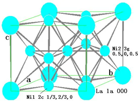
There is one molecule in the unit cell, that is, one La atom and five Ni atoms. The crystallographic position of the cell is:
| Atom | position | Coordinate |
| La | 1a | 0 0 0 |
| Ni-1 | 2c | 1/3 2/3 0; 2/3 1/3 0 |
| Ni-2 | 3g | 1/2 0 1/2; 0 1/2 1/2; 1/2 1/2 1/2 |
The crystal structure model and chemical bonding are shown in figure 17.
Before the charging reaches a certain stage, the embedded hydrogen atom occupies the interstitial position of the lattice and forms the solid solution. Hydride can be formed only when the cell volume increases to a certain percentage due to the intercalation of hydrogen atoms. Of course, the formation of hydride has a process of nucleation and growth. The discharge process should be a reverse process in which the hydrogen atoms preferentially leave the hydride lattice and gradually decompose the hydride, and then the solid solution hydrogen atoms leave the solid solution alloy. The maximum value of is 18. That is that maximum mass fraction of hydrogen storage of is [30].
d) Li intercalation mechanism of during charge and discharge
and both belong to the (No.166) R-3m space group. There are three molecules in the unit cell. 12 atoms, and their occupancy in the cell is:
Li (3a) 000; 2/3 1/3 1/3; 2/3 1/3 1/3
O (6c) 001/4; 2/3 1/3 7/12; 1/3 2/3 11/12;
00- 1/4; 2/3 1/3 1/12; 1/3 2/3 5/12
The crystal structure model and chemical bonding are shown in figure 16.
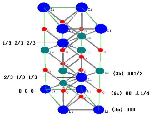
As can be seen from the diagram, the chemical bond between the Li atom at position 000 and the neighboring atom is longer, and its binding force in the crystal cell is weak. When charging starts, The Li atom at position 000 is preferentially separated from the crystal lattice. The crystal lattice is followed by the Li atom at 2/3 1/3 1/3; 2/3 1/3 1/3 position of the crystal lattice, so it is in the charged state. When , the lattice parameters and lattice strain change slowly, and then the rate of change is larger. In the process of discharge, it is roughly the reverse process, but it is not completely reversible.
The appearance of two with different composition when charging in the range of indicates that there is not a uniform de-Li of the whole cathode, but a process from the surface to the inside, and finally achieve a more uniform de-Li of the whole electrode. There is no phase transition during the whole charging and discharging process, but the fine structure (lattice parameters, micro-strain) and relative diffraction intensity, especially (006), of the positive active materials change most obviously due to de-Li and re-embedding Li.
e) The behavior of material during charge and discharge and the mechanism of Li deintercalation
Li atoms have four crystallographic positions in the lattice, namely:
As can be seen from figure 12, the bonding force at position 000 is the weakest, and the bonding force at position is the strongest, and that at position is similar to that at position . Therefore, under the action of a smaller electric field, the Li atom at position 000 first leaves the lattice until it becomes , and then the Li at position and leave successively. Until it becomes Li-deficient and , and finally, the Li atom at position 1/2 1/2 leaves until it becomes without Li. There may be four steps in the charge-discharge curve, the difference between the front and the last two steps is large, and the difference between the middle two steps is very small, the discharge process is on the contrary, which is proved by the experimental charge-discharge curve, as shown in figure 15.
![Fig. 15: Charging of Li/LiFePO4 and its differential curve [29]](https://doc.globaljournals.org/hjgb57_58331/ocr/images/derivatives/87/87c9f1da1914f5132ad1d2c96b6718b4d503a85335809133a34b4a75ac10f732.webp)
f) Behavior of graphite during charge and discharge
The structure of graphite is characterized by the extension of the hexagonal grid surface composed of carbon atoms in the network plane and the ABAB along the normal direction of the network plane. Or ABCABC. The former belongs to P63/mmc (No.194) space group and the latter is 3R-graphite and belongs to R3 (No.146) space group [15]. Based on the experimental results of Section 3.2, some behaviors of graphite in the process of charge and discharge can be summarized.
With the beginning of the charging process, the Li atom is embedded in the graphite layer, and its priority is to enter the gap position between the graphite grid faces, so that the lattice parameters a and c as well as the micro-strain of the graphite, are increased, and the stacking disorder P is also changed. Because the ABAB sequential stacking is not as dense as the dense hexagonal structure, it has a large gap space and can hold a large number of interstitial atoms, so the Li-C compound will not be formed when the charge is less than . Only when the battery charge is more than , , , and phases will be formed successively. Due to the precipitation of the new phase, there is a process of nucleation and growth, so there will be two-phase or polyphase coexistence in this process. As for the percentage of charge in which Li-C compounds are precipitated, it depends on the system of lithium-ion batteries and the proportion of positive and negative active materials.
Similar to the positive electrode, the 002,100 peaks of 2H-graphite are separated when the charge is less than , indicating that there are also two 2H- graphite phases with different composition, indicating that the graphite electrode also has a surface-to-inside process of embedding Li.
VI. PHYSICAL MECHANISM OF ELECTRICAL CONDUCTIVITY FOR SECONDARY BATTERY
At the beginning of charging, the migration of lithium ions (hydrogen ions) begins at the negative-electrolyte interface. Because lithium ion (hydrogen ion) is embedded in the negative electrode after obtaining (reducing) electrons at the negative electrode-electrolyte interface, the concentration of lithium ion (hydrogen ion) at the negative electrode-electrolyte interface decreases. In the solution, lithium ion (hydrogen ion) migrates from positive electrode to negative electrode like a relay race to make up for this concentration gap. Due to the directional migration of ions (hydrogen ions), the concentration of ions (hydrogen ions) is also reduced at the positive electrode-electrolyte interface. Under the action of electric field, the Li atoms in positive active materials and leave the lattice position (the hydrogen atoms in the leave the lattice position), reach the positive electrode-electrolyte interface, lose electrons (that is, oxidation), and enter the electrolyte. To supplement the lithium ion (hydrogen ion) in the electrolyte. When the ion flow reaches dynamic equilibrium, it corresponds to the charging platform of the battery. When the battery is fully charged, the Li atom (hydrogen atom) in the positive electrode is exhausted, and the ion (hydrogen ion) can only be provided by the electrolyte, so there must be ion (hydrogen ion) in the original composition of the electrolyte.
The discharge process is contrary to the charging process. Under the action of the reverse electric field, the ion in the electrolyte is reduced to atoms at the positive electrode-electrolyte interface and embedded back into the lattice position of the positive active material. Then the ion migrates from the negative electrode to the positive electrode like a relay race, resulting in a decrease in ion concentration at the negative electrode-electrolyte interface. Then the Li(H) atom in the negative active material leaves the lattice, loses electrons and becomes ion, which enters the electrolyte through the negative electrode-electrolyte interface, thus forming the discharge conduction process that the negative side Li(H) atom leaves the crystal lattice of the negative electrode active material, the positive side Li(H) atom is embedded back into the crystal lattice position of the positive electrode active material, and the ion flows directionally from the negative electrode to the positive electrode.
In short, the physical conductive mechanism of secondary battery is the directional migration of conductive ions formed by de-intercalation and re intercalation in positive and negative electrode active materials.
Table 1
| Materials and Working Mechanisms of Secondary Batteries | ||
| Authors | C. Z. Yang, Y. W. Lou, J. Zhang, X. H. Xie and B. J. Xia | |
| Publisher | Springer and Science Press in Beijing | |
| 2022 | ||
| Content synopsis | This book is a monograph on material characterization and the mechanism study during charge-discharge, cycle and storage for secondary batteries by X-ray diffraction et al methods. whole book consists of 6 parts and 21 chapters. Part. 1(chap.1,2) describes the key experimental techniques and data analysis methods of X-ray diffraction. Part.2 (Chap.3~8) introduces the preparation methods and X-ray diffraction characterization of electrode active materials, including β-Ni(OH)2, storage hydrogen alloy AB5, LiMeO2, LiFePO4and 2-H graphite.et al. In this two parts, several new methods have been developed:(1) The least square method of separating the multiple broadening effect of diffraction lines and program for solving microstructure parameters; (2)A solution of mixed occupation parameters for Ni/Li atoms at 3a and 3b crystallographic sites of materials such as LiNiO2, Li(Ni,Co)O2, Li(Ni,Mn)O2and Li(Ni,Co,Mn)O2; (3) A new technique for measuring the stacking disorder of hexagonal graphite. Part 3 (Chap.9~12) introduces the mechanism studies during charging and discharging for (Ni/MH), graphite/LiMeO2and graphite/LiFePO4batteries. Based on the phase transition theory, a new intercalation-de-intercalation theory and conduction mechanism of conductive ions are proposed; Part 4 (Chap.13~16) and part 5 (Chap.17~19) are the mechanism study of the of cycle process and storage process, respectively. In these two parts, through the comparative study of variation laws of battery performance and of fine structure and microstructure parameters of positive and negative active materials and diaphragm with cycle and storage process, the cycle and storage processes mechanism and battery performance decay mechanism are revealed; Part 6 (Chap.20 and 21) investigates the methods to improve the battery performance based on the understanding of decay mechanism of cycle and storage performances of batteries The research methods, contents and new results introduced in the book fully reflect the necessity and importance of interdisciplinary intersection and close cooperation between material physics and | |
| electrochemistry, X-ray diffraction analysis and battery experts in this kind of research. | ||
| Chapter | Chapter Name | page |
| 0 | Preface, Catalogue and the author's introduction | 38 |
| 1 | Experimental methods of material characterization and the mechanism research | 1 |
| 2 | X-ray Diffraction analysis Methods of Materials Characterization and Mechanism Research | 23 |
| 3 | Characterization of active material β-Ni(OH)2and AB5alloy | 61 |
| 4 | Solid state reaction and formation mechanism in the synthesis of LiMeO2materials. | 83 |
| 5 | Mixed Occupation of Ni/Li Atoms in LiMeO2Materials | 99 |
| 6 | Ordered-Disordered of Ni, Co and Mn in (3b) position for Li(Ni1/3Co1/3Mn1/3)O2 | 121 |
| 7 | Preparation and X-ray Diffraction Characterization of LiFePO4 | 139 |
| 8 | Preparation and X-ray analysis of carbon electrode materials for lithium-ion batteries | 159 |
| 9 | Solid electrolyte Interface Film on Graphite Surface of Lithium-Ion Battery | 207 |
| 10 | Mechanism Research of Charge-discharge Process for MH/Ni Battery | 227 |
| 11 | Mechanism of charge-discharge process of Graphite/LiCoO2and Graphite/Li(Ni1/3Co1/3Mn1/3)O2batteries | 247 |
| 12 | Mechanism Research of Charge-Discharge Process for Graphite/LiFePO4battery | 275 |
| 13 | Mechanism Research of Cycle Process for MH/Ni Battery | 297 |
| 14 | Mechanism Research on the Cycle Process of 2H-Graphite/Li(Ni,Co,Mn)O2Battery | 315 |
| 15 | Cycle mechanism of graphene/[Li(Ni0.4Co0.2Mn0.4)O2+LiMn2O4] | 339 |
| 16 | Mechanism of Cycle Process of Graphite/LiFePO4Battery | 351 |
| 17 | Mechanism research of Storage Process for MH-Ni Battery | 365 |
| 18 | Mechanism of Storage Process for Graphite/LiCoO2and Graphite/Li(Ni1/3Co1/3Mn1/3)O2batteries | 379 |
| 19 | Mechanism Research of Storage process for Graphite/LiFePO4Battery | 417 |
| 20 | Effect and Action Mechanism of β-Ni(OH)2Additive in MH/Ni Battery | 443 |
| 21 | The Method and Action Mechanism of Improving the Performance of Secondary Battery | 461 |
| The recommendation of three professorial experts | 491 | |
| Subject index | 495 | |
| The sum of the whole book | 497 + 38 = 535 | |