This paper presents the measurement and evaluation of radio signal attenuation by tree foliage. Attenuation measurements were conducted using two disjoint antennas, one operating as a transmitter and the other operating as a receiver. The system was setup such that the two antennas are operated in a line-of-sight mode with random medium (in this case the foliage) positioned between the two antennas. At the transmitting section, the network interface was used to enable data to be forwarded from one network transmission out at the path to the receive antenna. The attenuation obtained was found to be dependent on many factors and parameters of the trees like geometry of measurement, (either trunk or canopy path), state of trees foliation, frequency, canopy thickness among others. The results revealed that attenuation under free space condition is insignificant at 20m and 40m either at 20m the maximum attenuation is 25dB and 28dB at 40m. The attenuation under free space increases as the distance is increase. The result also revealed that under the effect of single tree and vegetation, part of the transmitted signals are being absorbed and scattered by the tree elements such as the leaves, branches, twigs and trunks though signals are more absorbed and scattered under vegetation condition than single tree.
## I. INTRODUCTION
The study of Signal propagation through vegetation is challenging due to nature of the vegetation either the vegetation density, measurement geometry or vegetation composition. In addition, vegetation is prone to environmental effects, such as wind, that often introduced dynamic variations in the channel (ITU-R, 2007). Trees attenuate the line-of-sight (Los) path or scatter the radiated wave, compelling it to follow different paths (multipath) to the receiver. Basically, waves may be diffracted, reflected and scatter along the propagation path, a situation that may degrade signal quality and reduce link distance. Also due to absorption of power, the radiated wave may be attenuated as it propagates through foliage to the receive antenna (Herben et al 2014). The level of attenuation is determined by the density of the tree elements (e.g. leave, twigs, and branches). Also, the attenuation is dependent on the frequency, depth of penetration into the tree, path geometry and leave state (either wet, dry, full-leaf or no-leaf) (Hashim et al, 2013).
In communication system, antennas are used to transmit information through the atmosphere from one point to another and radio wave propagation is very sensitive to the properties and effect of the medium located between the transmitting and the receiving antennas (Collin, 2013). There are often significant reductions in the level of the received signal if there are obstacles in the signal path (Pon et al, 2010). The interaction of radio wave with the obstruction reduces its received signal strength. For the fact that radio waves are very sensitive to obstacles, the existence of vegetation elements such as trees along the path of communication link have been found to play a great influence on the quality of service (Qos) in outdoor propagation is inevitable especially in suburban and rural areas, beside other factors from terrestrial objects that are diversified by buildings and mountains.
 Figure 1: LOS versus NLOS Transmissions
Signal distortion and fading caused by the motion of tree foliage obstructing the line-of-sight path as shown in figure 1 translates into variations in the amplitude and phase response of the channel. Knowledge of the variations in the amplitude and phase response of the channel is critical in order to efficiently design a system that can compensate for these variations (ITU-R, 2012). Elements such as hills, buildings, or trees located on the path of the RF signal affect the way the signal propagates. Most of the changes occurring on the signal propagation paths can be explained in terms of reflection, diffraction, and scattering. Reflection occurs when the electromagnetic wave impinges the smooth surface of an object having a size much larger than the wavelength of the RF signal. Diffraction takes place when a very dense object with a sharp edge is located very near the LOS path. Waves bend over the sharp edge of the structure and reach the receiver (Michael, 2013). If the object is opaque and is in the line-of-sight path, then the only signal reaching the subscriber's antenna is the diffracted signal. This phenomenon is called shadowing since the signal reaches the receiver despite the total obstruction of the LOS signal. Scattering occurs when the electromagnetic wave impinges upon objects of size comparable to or shorter than the wavelength (Meng et al 2009; Meng et al 2010).
The aim of this study is to investigate the influence of trees (foliage) on radio signal at transmission frequency of 2,450MHz and to determine the dependence of propagation loss due to tree foliage. Most of the available researches in this subject area within the study location have been limited to few parameters of trees like depth (df) and operating frequency (f). The effects of other parameter of trees like leaves, twig and Branches on signal attenuation have been investigated with inadequate results. This has left a research gap which must be filled in order to get a more comprehensive technique. One of the ways to achieve this is to consider the effects of individual elements of trees.
The antenna (both transmitter and receiver) used in this study are horizontally polarized. The polarization state of the transmitted electromagnetic wave was affected by the vegetation that acts as a scatter (Perras and Bouchard, 2010). Some of the energy from the transmitted horizontal polarization state is transferred to the vertical polarization state by scattering or reflection of the transmitted electromagnetic wave. As shown in figure 2, the middle graph shows a horizontally polarized wave that could be generated by scattering or reflection of the vertically.
 Figure 2: Creation of an Elliptically Polarized Wave ( $\Delta \theta = \pi / 5$ )
If the phase difference, $\Delta \theta$, between the vertically polarized and horizontally polarized waves differs from $\frac{\pi}{2}$, $k = 0,1,2,\ldots$, then these waves combine into an elliptically polarized wave, as shown by the bottom graph of Figure 2, when $\Delta \theta = \frac{\pi}{5}$.
The polarization state of the RF signal resulting from the combination of the vertically polarized and horizontally polarized waves is function of the difference of phase, $\Delta \theta$, but also of the amplitudes, $E_{0x}$ and $E_{0y}$, of these two waves. The polarization state of the receive signal, based on these parameters, is given by
$$
\left(\frac{E_{y}}{E_{0y}}\right)^{2} + \left(\frac{E_{x}}{E_{0x}}\right)^{2} - 2\left(\frac{E_{x}}{E_{0x}}\right)\left(\frac{E_{y}}{E_{0y}}\right)\cos(\Delta\theta) = \sin^{2}(\Delta\theta) (1)
$$
Where $E_x$ is the horizontally polarized component of the receive signal, $E_y$ is the vertically polarized component of the receive signal. When $\Delta \theta = \frac{\pi}{2} + 2k\pi$, $k = 0,1,2,\ldots$, and $E_{0x} = E_{0y} = E_0$ then equation 1 becomes
$$
\left(E _ {y}\right) ^ {2} + \left(E _ {x}\right) ^ {2} = \left(E _ {0}\right) ^ {2} \tag {2}
$$
Each branch and each leaf on the RF signal propagation paths will affect $E_{0x}$, $E_{0y}$, and $\Delta \theta$ differently. This will result in a receive signal that can be modeled as the sum of an elliptically polarized signal and an unpolarized signal corresponding to noise. Both of these signals vary with time, especially when the wind blows through the trees and changes the structure of the foliage. The system devised in this research measures the temporal variation in the vertically polarized component of the receive signal. The effect of the leaves may change when the leaves are wet since the RF signal is in the 2450 MHz frequency range and water is known to absorb radio waves in that frequency range.
## II. METHODOLOGY
The experiment was carried out at Federal College of Forestry Jos. Attenuation measurements are conducted using two disjoint antennas, one operating as a transmitter and the other operating as a receiver. The system was setup such that the two antennas are operated in a line-of-sight mode with random medium (in this case the foliage) positioned between the two antennas. At the transmitting section, the network interface was used to enable data to be forwarded from one network transmission out at the path to the receive antenna. Along the transmission path lays either a tree or group of trees, which obstructs the radio signal. The receiving section consisted of a Router networking device that was connected to a computer for data logging, a stabilizer for power regulation and an uninterruptible Power Supply (UPS) to provide emergency power whenever there was power disruption, which might eventually result in data loss. The Router was adjusted to a transmission frequency of 2450 MHz at sampling rate of 500ms. The receiver antenna was directional while the transmitting mast had no restriction. Investigation site captures ranges from 20m to 80m at intervals of 20 meters with a constant power of $\pm 19$ dB from the transmitters.
### a) Free Space Path Loss Method
Free space path loss occurs as the signal travels from transmitter to receiver through space without any other effects attenuating the signal (Sharma and Singh, 2010). Free space path loss is dependent only on the distance from the transmitting antenna. In free space, the path loss increases by 20dB per decade. The equation used to determine free space follows (Idah, 2004)
$$
PL_{FS} (\mathrm{dB}) = 32.4 = 20\log (r) + 20\log (f)\tag{3}
$$
Equation (3) can be simplifies as
$$
PL_{FS} (\mathrm{dB}) = 32.4 = 20\log (r^{*}f)\tag{4}
$$
Where
PLFS = free space path loss
$$
r = \text {t h e d i s t a n c e f r o m t h e t r a n s m i t t e r (K M)}
$$
f = the frequency
### b) Single Trees Path loss Method
Presented in this section are analysis of measured data and results for isolated trees which culminated into prediction of propagation loss parametric equation more suitable for isolated trees. The parametric equation incorporated both the free space loss and tree loss factors. The tree loss factor is incorporated in the technique to calculate for the increase in attenuation of the receive signal when radio waves propagates through a tree. The tree loss factor is incorporated in the method to calculate for the increase in attenuation of the received signal power when the receiver is placed behind a tree. The expression for the path loss from the transmitting antenna to a receiving antenna in the presence of a tree is written as (perras and Bouchard, 2010);
$$
P L _ {\text{tree}} = L _ {F S} + L _ {t} \tag{4}
$$
Where;
$PL_{tree} =$ Path loss in the presence of a tree.
$\mathsf{L}_{\mathsf{FS}} = \mathsf{Free}$ space loss.
$L^{\mathrm{t}} =$ Tree loss factor.
### c) Method used for Simulating Group of Trees (Vegetation) Path Loss
An analysis was conducted over group of trees in the path of the transmitted radio signal based on the following steps.
Step 1: Evaluation of the Equivalent value of the total cross section of leaves and Branches of the vegetation canopy tree.
The equivalent value of the total cross section of leaves and branches of the vegetation canopy tree is given as
$$
\sigma^ {e q} = n _ {i} \left(\sigma^ {t l}\right) + \sum_ {b = b 1} ^ {n} n _ {b} \left(\sigma^ {t b}\right) \tag {5}
$$
Where $\sigma^{\mathrm{tl}}$ equals the cross section of a single leaf, $\sigma^{\mathrm{tb}}$ is the cross section of a single branch, $n_i$ is the number of leaves of a tree canopy, $n_b$ is the number of branches of a vegetation canopy tree, and $b = b1$, $b2$, $bn$ is the number of branches of different size categories. We first evaluated the mean value of cross section of a single leaf from
$$
\langle \sigma^{\mathrm{tb}} \rangle = \int_{0}^{2\pi} \int_{-2}^{\frac{\pi}{2}} \sigma^{\mathrm{tb}} (\theta , \phi) f_{\theta}^{1} (\theta) f_{\phi}^{1} (\phi) \cos \theta \, d\theta \, d\phi \tag{6}
$$
The leaf cross section is averaged over angles $\phi$ and $\theta$ with $0 \leq \theta < 2\pi$, $f\phi^{1}(\phi) = 1$, $-\frac{\pi}{2} \leq 0 < \frac{\pi}{2}$, and $f\theta^{1}(\theta) = 1$. Therefore equation 6 becomes:
$$
\langle \sigma^ {\mathrm {t l}} \rangle = \int_ {0} ^ {2 \pi} \int_ {- 2} ^ {\frac {\pi}{2}} \sigma^ {\mathrm {t l}} (\theta , \phi) \cos \theta d \theta d \phi \tag {7}
$$
Step 2: evaluation of the Free Space loss.
The free space loss is given as;
$$
L _ {f s} = \frac {(4 \pi f r) ^ {2}}{C ^ {2} D _ {t} D _ {r}} \tag {8}
$$
Where $r$ is the distance from the transmitting antenna to the receiving antenna (in meters), $f$ is the frequency of transmission (in MHz), $C$ is the velocity of light in air, $D_t$ is the directivity gain of the transmitting antenna, and $D_r$ is the directivity gain of the receiving antenna. Multiply the result gotten from the free space loss and result from attenuation of the mean values of the total cross section per unit volume of the vegetation canopy tree, either
$$
L _ {f s} = \frac {(4 \pi f r) ^ {2}}{C ^ {2} D _ {t} D _ {r}} \times 4 \left[ n _ {i} \left(\sigma^ {t l}\right) + \sum_ {b = b 1} ^ {n} n _ {b} \left(\sigma^ {t b}\right) \right] \tag {9}
$$
Therefore, the vegetation canopy tree path loss converted to decibel (dB) is given as;
$$
P L _ {v e g} = 1 0 \log \left\{\frac {(4 \pi f r) ^ {2}}{C ^ {2} D _ {t} D _ {r}} \times 4 \left[ n _ {i} \left(\sigma^ {t l}\right) + \sum_ {b = b 1} ^ {n} n _ {b} \left(\sigma^ {t b}\right) \right] \right\} (1 0)
$$
## III. RESULTS
In this section, results from field measurement under free space condition and that where the Radio wave is obstructed by a single tree and group of trees (vegetation) are presented.
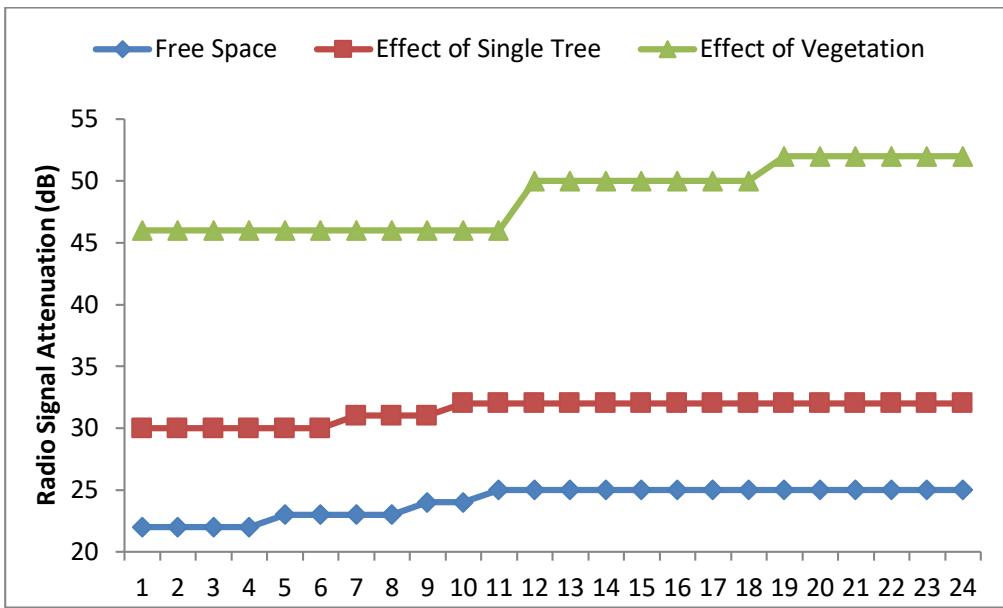
 Figure 3: Radio signal attenuation under Free Space Condition, behind a Tree, and inside vegetation at a distance of 20m
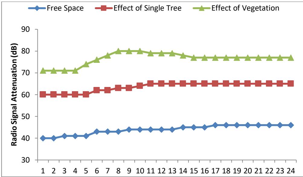 Figure 4: Radio signal attenuation under Free Space Condition, behind a Tree, and inside vegetation at a distance of 40m
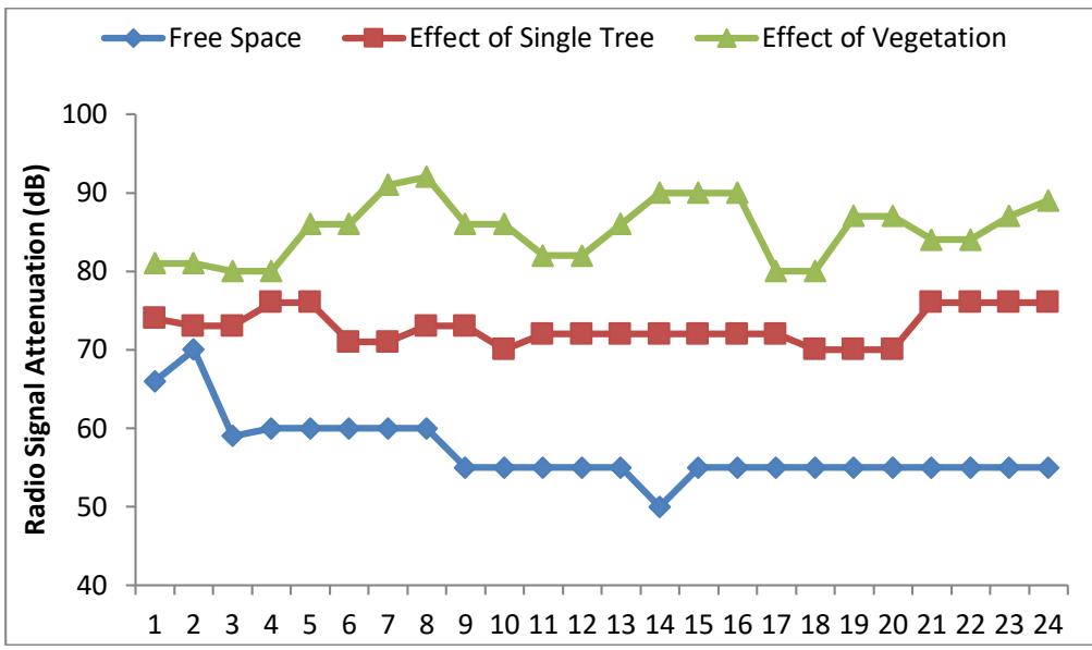 Figure 5: Radio signal attenuation under Free Space Condition, behind a Tree, and inside vegetation at a distance of 60m Figure 6: Radio signal attenuation under Free Space Condition, behind a Tree, and inside vegetation at a distance of 80m
## VI. DISCUSSIONS
Figure 3, figure 4, figure 5 and figure 6 presents the radio signal attenuation under Free Space Condition, behind a Tree, and vegetation at a distance of $20\mathrm{m}$, $40\mathrm{m}$, $60\mathrm{m}$ and $80\mathrm{m}$ respectively. Figure 3 and figure 4 shows that attenuation under free space condition is insignificant at $20\mathrm{m}$ and $40\mathrm{m}$ either at $20\mathrm{m}$, the maximum attenuation is $25\mathrm{dB}$ and $28\mathrm{dB}$ at $40\mathrm{m}$. The attenuation under free space increases as the distance is increase as shown in figure 5 and figure 6. The result further shows that under the effect of single tree and vegetation, part of the transmitted signals are being absorbed and scattered by the tree elements such as the leaves, branches, twigs and trunks. As it can be seen from the results, the signals are more absorbed under vegetation condition than single tree. This is in agreement with the reports by Zhimwang et al (2021) and Ndzi et al (2012) which stated that attenuation under vegetation is more pronounce than that of the single tree.
## V. CONCLUSION
The measurement and evaluation of radio signal attenuation by tree foliage was conducted in the federal college of forestry Jos. The attenuation was found to be dependent on many factors and parameters of the trees e.g. Geometry of measurement, (either trunk or canopy path), state of trees foliation, frequency, canopy thickness among others. The results revealed that attenuation under free space condition is insignificant at 20m and 40m either at 20m the maximum attenuation is 25dB and 28dB at 40m. The attenuation under free space increases as the distance is increase. The result also revealed that under the effect of single tree and vegetation, part of the transmitted signals are being absorbed and scattered by the tree elements such as the leaves, branches, twigs and trunks though signals are more absorbed and scattered under vegetation condition than single tree.
Generating HTML Viewer...
References
12 Cites in Article
R Collin (2013). Antennas and Radio Wave Propagation.
M Hashim,Saunder Mavrakis D And (2013). Measurement and analysis of temporal fading due to moving vegetation.
A Herben,Yvo (2014). A Tree Scattering Model for Improved Propagation Prediction in Urban Microcells.
(2007). Attenuation in Vegetation Itu-R Recommendation.
Westphal Dietrich (2012). International Telecommunication Union (ITU).
J Zhimwang,E Ogherohwo,D Iliya,Ibrahim Aminu,O Shaka (2021). Measurement and Prediction of Received Signal Level and Path Loss through Vegetation.
Yu Meng,Yee Lee,Boon Ng (2009). STUDY OF PROPAGATION LOSS PREDICTION IN FOREST ENVIRONMENT.
Yu Meng,Yee Lee (2010). INVESTIGATIONS OF FOLIAGE EFFECT ON MODERN WIRELESS COMMUNICATION SYSTEMS: A REVIEW.
A Michael (2013). Further Investigation Into Vhf Radio Wave Propagation Loss Over Long Forest Channel.
David Ndzi,L Kamarudin,Abdul Muhammad Ezanuddin,A Zakaria,R Ahmad,Mohd Malek,A Shakaff,M Jafaar (2012). VEGETATION ATTENUATION MEASUREMENTS AND MODELING IN PLANTATIONS FOR WIRELESS SENSOR NETWORK PLANNING.
S Perras,L Bouchard (2010). Fading characteristics of RF signals due to foliage in frequency bands from 2 to 60 GHz.
Evizal Abdul Kadir,Siti Shamsuddin,Tharek Abdul Rahman,Sharul Abdul Rahim,Eko Supriyanto,Sri Listia Rosa (2010). AIS Algorithm for Smart Antenna Application in WLAN.
No ethics committee approval was required for this article type.
Data Availability
Not applicable for this article.
How to Cite This Article
Shaka O. S. 2026. \u201cMeasurement and Evaluation of Radio Signal Attenuation by Tree Foliage: A Case Study of Federal College of Forestry Jos, Nigeria\u201d. Global Journal of Science Frontier Research - A: Physics & Space Science GJSFR-A Volume 22 (GJSFR Volume 22 Issue A4): .
Explore published articles in an immersive Augmented Reality environment. Our platform converts research papers into interactive 3D books, allowing readers to view and interact with content using AR and VR compatible devices.
Your published article is automatically converted into a realistic 3D book. Flip through pages and read research papers in a more engaging and interactive format.
This paper presents the measurement and evaluation of radio signal attenuation by tree foliage. Attenuation measurements were conducted using two disjoint antennas, one operating as a transmitter and the other operating as a receiver. The system was setup such that the two antennas are operated in a line-of-sight mode with random medium (in this case the foliage) positioned between the two antennas. At the transmitting section, the network interface was used to enable data to be forwarded from one network transmission out at the path to the receive antenna. The attenuation obtained was found to be dependent on many factors and parameters of the trees like geometry of measurement, (either trunk or canopy path), state of trees foliation, frequency, canopy thickness among others. The results revealed that attenuation under free space condition is insignificant at 20m and 40m either at 20m the maximum attenuation is 25dB and 28dB at 40m. The attenuation under free space increases as the distance is increase. The result also revealed that under the effect of single tree and vegetation, part of the transmitted signals are being absorbed and scattered by the tree elements such as the leaves, branches, twigs and trunks though signals are more absorbed and scattered under vegetation condition than single tree.
Our website is actively being updated, and changes may occur frequently. Please clear your browser cache if needed. For feedback or error reporting, please email [email protected]
Thank you for connecting with us. We will respond to you shortly.