
I. INTRODUCTION
The most well-known method of holding transformable structural elements is using pyrotechnical devices installed outside the equipment area. This system results in high-impact forces.
This lack of pyrotechnical products led to the emergence of electromechanical initiating devices. [1, 2]
There are known designs of electromechanical devices [3] based on heating the structural elements of the devices when an electric current is passed through them. The most famous are devices based on:
- Materials that expand during heating, for example, paraffins.
- Fusible elements that lose their load-bearing capacity when heated;
- Heating knives that violate the integrity of load-bearing elements;
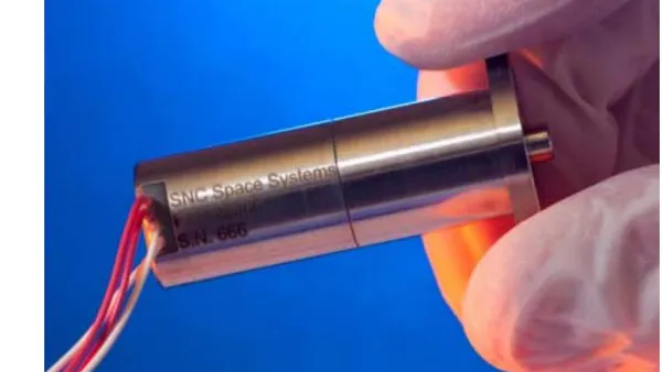
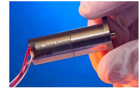
The EH-3525 is an initiator device developed by Sierra Nevada Corporation that uses a material that expands during heated. (Figure 1a)
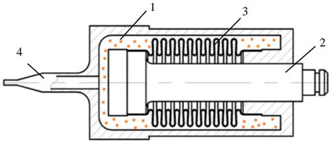
The EH-3525 uses a heating element to melt the wax in the drive. The design diagram is shown in Figure 1b. Paraffin expands during heating and hydraulic pressure pushes the rod out. The rod is moves back, when the paraffin cools.
Some characteristics of the EN-3525 drive are presented in Table 1.
The advantages of such devices include the high force created when the rod moves, which allows them to be used in more heavily loaded systems. However, the presence of a heated material and its transformation into a different state of aggregation forces a large amount of energy to be supplied to the device, and the response of such devices takes a long time.
| Parameter | Meaning |
| Weight, g | 35 |
| Response time, s | 200 |
| Nominaloutputforce, N | 156 |
An initiating device based on heating knives can include a device protected by patent RU 2307772 C2 (ZAO «KB «Polet») [4](Figure 2).
The rod of the initiating device of this design is moved by a compression spring. The spring is compressed when the element being held is fixed. The rod is kept from moving using a high-strength thread, such as polyimide, Kevlar and Vectran. The device is triggered when the filament is destroyed/melted, using heating knives representing a wound incandescent spring.
The advantages of such devices include the high force created when the rod moves, which allows them to be used in more heavily loaded systems. In addition, such devices have a faster response/actuation time and consume less energy compared to initiating devices based on the principle of an expanding structural element.
However, excessive heat may cause the knife to melt. Then the initiating device may fail. This phenomenon determines high demands on knife coatings and precise regulation of the electric current supplied to the knives.
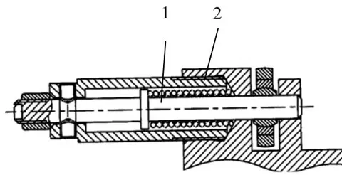
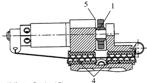
1 – Rod; 2 – Compression Spring; 3 – High-Strength Thread; 4 – Heating Knife; 5 – Retained Element
The characteristics of such a device, established by experimental and calculation methods, are presented in Table 2.
| Parameter | Meaning |
| Weight, g | 80 |
| Response time, s | 5 |
| Nominaloutputforce, N | 150-200 |
Initiating elements based on fusible elements include a device protected by patent RU 2707901 C1 (RESHETNEV), the design of which is shown in Figure 3 [5, 6].
Fixation of the initiating device rod from axial movement under the influence of a compression spring is ensured by a split ring tightened with nichrome wire. When an electric current is applied through the nichrome wire, it heats up and melts/destroys, ensuring the mechanism operates. The design of the split ring ensures a reduction in the force coming from the spring, allowing the use of small-diameter nichrome wire.
The advantages of this type of mechanism include low electrical current consumption and fast response/ operation of the device.
The disadvantages of this design include the low force generated by the device, determined by the diameter of the fusible element, which is .
The characteristics of the initiating device are presented in Table 3.
| Parameter | Meaning |
| Weight, g | 50 |
| Response time, s | 1 |
| Nominaloutputforce, N | 60 |
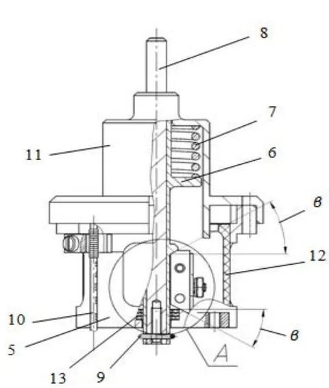
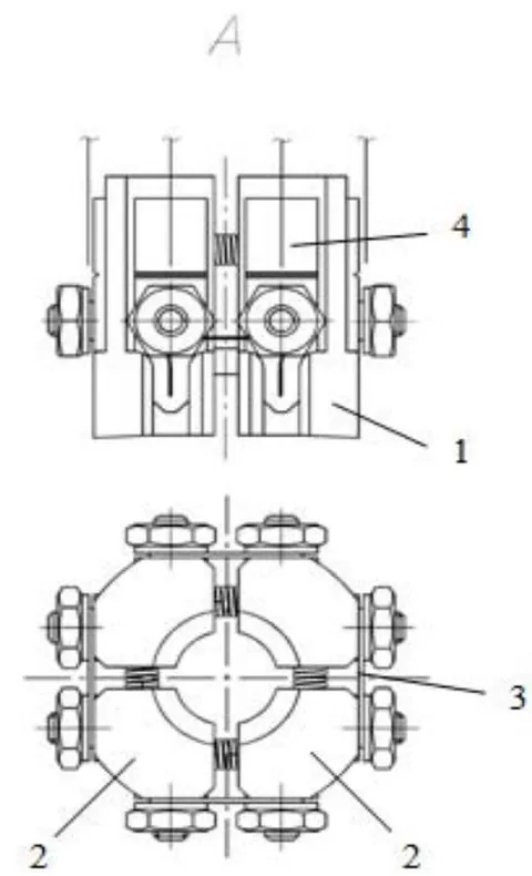
1 - split ring; 2 - segments; 3 - initiating element (wire); 4 - contacts; 5 - body; 6 - piston; 7 - spring; 8 - rod; 9 - wire; 10 - cable; 11 - cover; 12 - insulator; 13 - damper
Increasing requirements for structures determine the need for new technical solutions and combine the advantages of different systems.
The use of a fusible element makes it possible to obtain low current consumption. However, to increase the load-bearing capacity of the structure, it is necessary to increase the reduction of the system, which is held by the fusible element.
One of the solutions in this area was proposed by COOPER. Reducing the force on a small diameter wire (reduction) is achieved here by distributing the power over the coils of the tension spring.
The design of the initiating device developed by COOPER is shown in Figure 4.
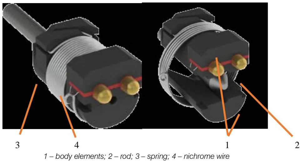
The body elements tightened by a torsion spring. The torsion spring is made of a small diameter wire and is held by nichrome wire with a diameter of 0.1 mm.
Let's consider the kinematic diagram of the COOPER design [7,8]. Figure 5a shows the force distribution for one turn of the garter spring. Let us accept the assumption that the coil is a closed ring, then the reaction in the loop willequal half the force coming to the body element.
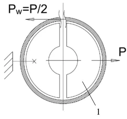
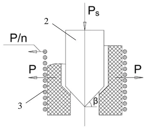
Let us determine the theoretical maximum permissible load on the rod of a structure with a wire with a diameter of 0.1 mm made of X20N80 material. The tensile strength of the wire is 0.6 kg. When fixing the wire in like the COOPER design, we assume that the maximum force will be 1.2 kg [9, 10, 11].
The maximum permissible load will be calculated using formula (2):
According to Figure 4, the number of turns of the compressed spring is , and the angle of inclination of the rod chamfer . Let us assume that there is no friction in the rod-body element pair. Thus, the theoretical maximum permissible load on the device rod is ( ).
Based on the calculation results, we calculate the device reduction coefficient using formula (3):
The adopted design solutions and the kinematic diagram of the mechanism make it possible to significantly increase the nominal output force of the device, even in comparison with devices based on the principle of materials expanding during heating. At the same time, the electrical characteristics correspond to devices based on fusible elements.
However, to further increase the output force, a different kinematic scheme of the device was proposed and analyzed [12].
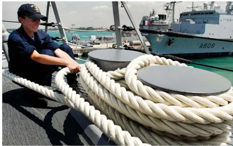
The principle on which the operation of the device is based is well known from navigation, namely from the possibilities of mooring ships (see Figure 6). When a vessel pulls on a rope wound around a bollard, the rope is pressed against the bollard, and frictional forces are generated, further holding the cord from being pulled out. Thus, minimal power is required from the free end of the have to hold it.
Let's consider the kinematic diagram of the developed mechanism, presented in Figure 7a, b, c.
The rod is kept from moving by wedges installed in the grooves of the body element. The wedges are tightened by a torsion spring. However, the torsion spring is wound on three sectors of the body element. Two sectors of the body element do not contain grooves for wedges. One sector contains grooves for wedges. This design allows the reduction process to be divided into two stages.
The first reduction stage will be similar to the kinematics of the COOPER device (see Figure 7b). This calculation scheme will be valid for turns of torsion springs installed on wedges. The load can be calculated using formula (4).
where is the number of elements installed along the end of the wedge.
The secondreduction stage can be determined according to the scheme presented in Figure 7c [13].
Let the force be the tension force of the torsion spring, corresponding to its winding angle on the body element, be the normal reaction of the body element to a section of the spring with length . From the condition of equilibrium of the three forces and , up to tiny values of the angle , the equalities follow:
where is the frictional force acting on the specified element. According to the condition, , from (5) and (6), we obtain the relation:
where is the load of the fusible element (tension of the nichrome wire), is the friction coefficient.
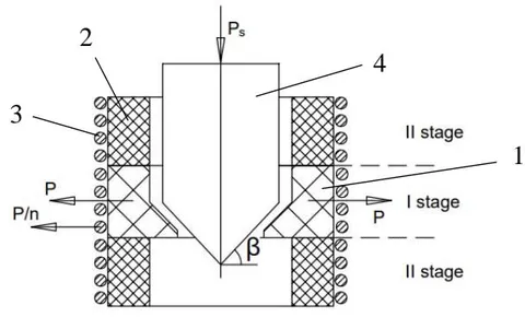
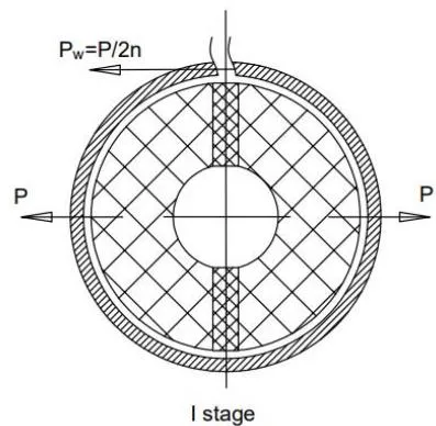
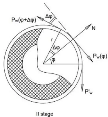
1-cracker;2-body element;3-spring;4-rod
C
is calculated by combining equations (4) and (9).
Calculate the theoretical maximum load Ps on the rod using Formula 10. We divide the distribution of the spring over the body of the device into three equal parts, then, provided the total number of turns is 12, , and . The friction coefficient is taken equal to 0.3. The wire is fixed in a similar way to the COOPER initiating device. kg. Thus, the theoretical maximum permissible load on the rod of the device being developed is 35986 kg ( N).
The reduction coefficient , which is 624 times higher than the kinematic diagram of the COOPER device, all other things being equal.
It was analytically determined that the selected kinematic scheme is promising regarding force reduction. The number of turns determines the degree of removal of the system while increasing the turns on the stationary part of the body element increases the reduction exponentially.
To confirm the calculations, samples of initiating devices were made, as shown in Figure 8. The spring was wound with 12 turns in the same way as in the design case.
The test scheme is shown in Figure 9 [14]. During the tests, the force that was applied to the rod of the initiating device was monitored - (in the axial direction), as well as the force that was created at the end of the spring, secured with nichrome wire - . The response time was also monitored during testing.
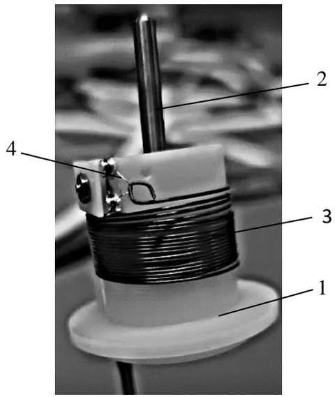
Figure 8: Sample Initiating Device
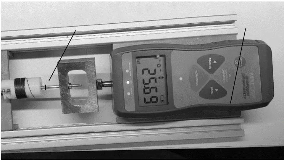
1 - layout of the initiating device; 2 - dynamometer
The test results are shown in Tables 4 and 5.
| Rodloa dPs, kgf | Friction coefficient μ (wire-polyamide) | Design springtension | CalculatedSpr ingreductionf actor | Actual spring tension Pw, kgf | Reduction ratio k devices actual | Safety factor of nichrome wire with a diameter of 0.1 mm |
| 5 | 0,05 | 0,089 | 56 | 0,09 | 55 | 13 |
| 10 | 0,179 | 0,12 | 83 | 10 | ||
| 15 | 0,269 | 0,14 | 107 | 8,5 | ||
| 20 | 0,359 | 0,15 | 132 | 8 | ||
| 30 | 0,538 | 0,19 | 151 | 6,3 |
| Diameter of nichrome wire, mm | Response time, s | ||
| Electric currentstrength 2 A | Electric current 3 A | Electric current 4 A | |
| 0,1 | 0,2 | 0,1 | 0,05 |
The maximum load created on the experimental sample was , and there was no destruction of nichrome wire with a diameter of (safety factor of the wire 6.3). The maximum response/activation time of the initiating devices is at a current of .
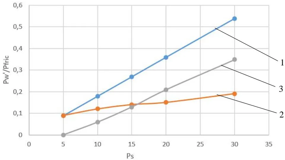
Figure 10 shows a graph of the increase in load on the wire. The design case is presented with a friction coefficient between the wedges, rod, and body element (only the friction coefficient between the spring and the body element was considered). Actual data revealed a rise in the reduction coefficient, which is due to an increase in friction forces with increasing load; at low loads, the reduction coefficient corresponds to the design case.
A comparison of the characteristics of devices of different types is presented in Table 6.
| Parameter | Meaning | ||||
| Expandingelement (EN-3525 drive) | Heatingknives | Fusibleelement (RESHETNEV) | Fusibleelement (COOPER) | Promisings ample | |
| Weight, g | 35 | 80 | 50 | 35 | 35 |
| Response time, s | 200 | 5 | 1 | 0.2 orless | 0.2 orless |
| Nominaloutput force, N | 156 | 150-200 | 60 | 560 | morethan 560 |
Based on the test results, it was revealed that the mechanisms of this design have a high reduction coefficient. The kinematic scheme makes it possible to obtain a high nominal output force equal to or greater than initiating elements based on the principle of expanding structural elements and heating knives while maintaining the electrical characteristics inherent in initiating devices based on fusible elements. As the force on the retaining part of the structure increases, the reduction coefficient of the mechanism also increases due to an increase in the resistance forces between the rod and the wedges and between the wedges and the body elements.
The characteristics obtained from testing prototypes show that structures of this type are promising for use in devices for holding spacecraft mechanical systems.