
I. INTRODUCTION
Shear walls are essential structural components that effectively withstand both gravity and lateral loads exerted on buildings. Their primary function is to provide lateral stiffness to buildings, thereby effectively resisting seismic forces that may arise from an earthquake. They provide lateral support for buildings. Shear walls are generality important in tall/high-rise buildings subjected to wind, seismic and other lateral forces. They are constructed from the foundation to the top story. Shear walls resist shear forces and uplift forces. Shear walls transfer horizontal forces to other components in the load path. They should be located on each level of the structure. Shear walls can have openings for windows and doors. The size and location of Shear Wall affects the seismic response. Owing to their numerous benefits to structural design, shear walls have become increasingly popular in building construction. However, their placement is crucial and requires careful evaluation. Ideally, in a floor layout, shear walls should be positioned as close as possible to the center of mass to prevent any additional moments that may arise otherwise. Therefore, it is imperative to utilize the appropriate number of shear walls with the appropriate cross-sectional area.
This study investigates the story Response parameters in all seismic zones using Shear Wall and Columns in RC framed structures. G+31 buildings are considered in different seismic seismic of India. Finite element software ETAB v 21 is used for analysis.
II. OBJECTIVE
To analyse/Investigate the Seismic Behavior of the building of height on Shear Wall and Column Configuration by Etabs software and find various parameter such as Max. Story Displacement, peak story shear, base shear, axial forces, Overturning Moment and story drift, in all seismic zones using Linear Dynamic Method on FEM based software as per IS 1893 (Part-I): 2016.
III. METHODOLOGY
In general Structures are analysed in Software for finding more frequent results for multiple iterations, Therefore, A building is analysed in Etabs Software Which is FEM Based and Having good UI. Linear Dynamic Method (Response Spectrum) used for analysis on multiple modes (Shapes).
A General Outline of the method is used as below:
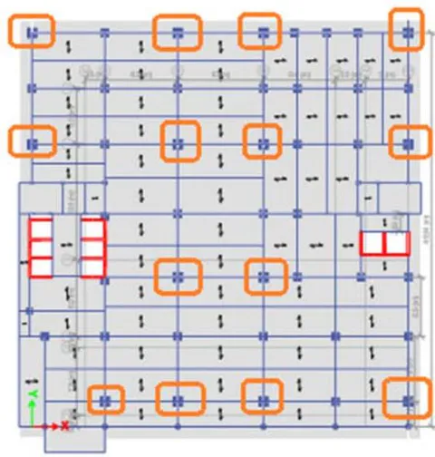
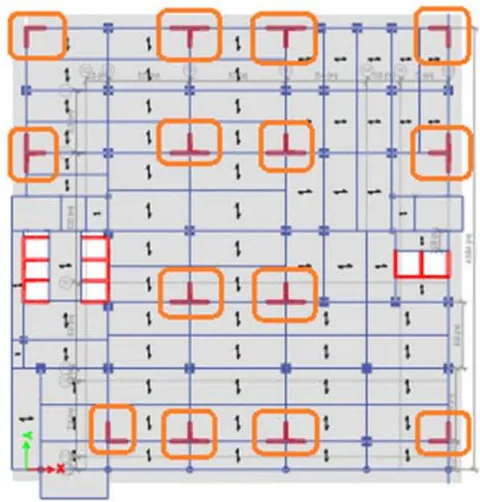
Selected a Real geometry of almost Square Shape and Done the Analytical modelling on Etabs, followed through the assignments of defined x-sections, Loads and their Combinations, Diaphragm, Support
Conditions at base. And Lastly Analysed the structure on Selected Modes and Load Combinations.
a) Present Work Description
Taking a story Tall building, modelled and Analysed in ETABS 2021. Analysis Done on both option either building will be analysed on columns or on Shear Wall. So, in this Study, comparison of Parameters Like Max. Story Displacement, Max. Story drift, Story Shear, Base Shear, Overturning Moment, Axial Force is done on the both of the Structural System.
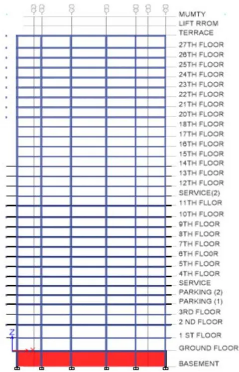
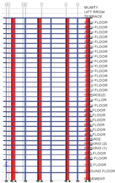
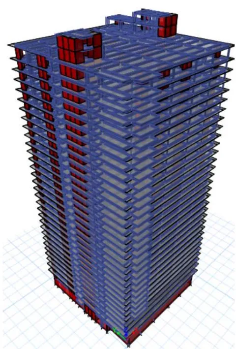
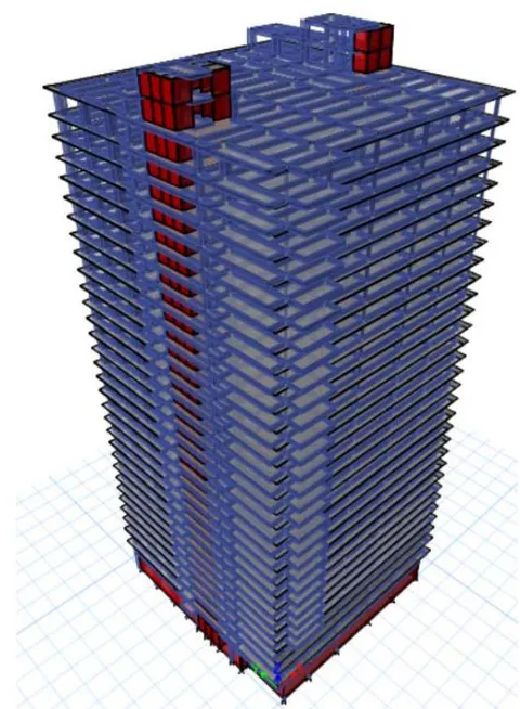
b) Specification of the Model
Following data used for analysis of as above mentioned RC frame building model.
| SPECIFICATION | DATA |
| Model | B+G+31 |
| Plan Size | 43mx44m |
| Total Building Height | 108m |
| Floor to Floor Height | (5.2x1) + (4.2x2) + (3.35x2) + (3.0x3) + (3.2x6) + 3.6 + (3.2x16) + 3.9 + (3x2) |
| No. of bays along, X-direction | 5 |
| No. of bays along, Y-direction | 6 |
| Column size | 1200x1200,1000x1000,600 dia. |
| Beam size | 200x500, 300x500,300x600,400x600 |
| Slab Thickness | 150mm |
| Shear wall Thickness | 400thk., 300thk.(For Lift only) |
| Inner Wall Thickness | 230mm AAC Block (Density- 1000kg/m3) |
| Outer wall | 230mm AAC Block (Density- 1000kg/m3) |
| SPECIFICATION | DATA |
| Grade of Concrete | For Column/Shear Wall- M40 |
| For Slabs/ Beams -M30 | |
| Grade of Steel | Fe500 |
| Density of Brick | 1000Kg/m3 |
| Unit weight of RCC | 2500kg/m3 |
| SPECIFICATION | DATA |
| Seismic Zone | Zone II, III, IV & Zone V |
| Zone Factor corresponding to seismic zone | 0.1,0.16,0.24,0.36 (as per table 2 of IS:1893(Part-1-2016) |
| Importance Factor | 1.2 (as per table 6 of IS:1893(Part-1-2016) |
| Response Reduction Factor | 3 (as per table 7 of IS:1893(Part-1)-2016) |
| Type of frame | Ordinary RC moment resisting frame (as per Table-7; IS 1893:2016) |
| Damping Ratio | 5% |
| Soil Type | Medium Soil (Type II) |
c) Load Calculations
- Dead load (Table 2 as per IS 875(part1):1987)
On floor slabs:
Self-weight
Partition wall (assumed)
Floor finish (assumed)
DL on floors
(As per clause 7.3.1, table 8 of IS1893 (part 1): 2016, for imposed uniformly distributed floor loads of or below, the% age of imposed load is .)
Total DL on the floor
On roof slabs:
Self-weight
DL on floors
(As per clause 7.3.2 of IS 1893 (part 1): 2016, for calculating the design seismic force of the structure, the superimposed load on top roof need not to be considered.)
Total DL on roof
2. Live load (Table 1 as per IS 875(part 2):1987)
Live load on floors
Live load on roof
3. Seismic Calculations (Linear Dynamic Method)
Response Spectrum Analysis: Qik = Ak ik Pk Wi
Where, Qik is Design lateral force at the floor I in mode k.
Ak is the Design horizontal acceleration spectrum value for the mode of vibration.
is Mode Shape coeff. at a Floor I in mode k.
Pk Modal Participation factor of the mode k.
Wi Seismic weight of the floor i.
User will provide Ak and Wi. In these Ak can be provided by specifying Seismic parameter configuration. Wi can be provided by specifying self-weight contribution in X, Y, Z direction with factor 1 and dead load and appropriate live load in all three directions. Response Spectrum Method 53 of analysis shall be performed using the Design Spectrum-
ETABS utilizes following procedure to generate the lateral seismic loads:
- User provides the value of Z I as factors for input spectrum. 2 R
- Program calculates time period for the first 12 modes or as specified by the user.
- Program calculates for each and every mode in respect of time period & damping.
- The program calculates design horizontal acceleration spectrum for different modes.
- The program also calculates mode participation factor for different modes.
- The Peak lateral seismic force at every floor in each mode is calculated.
- All the response values for each mode are calculated.
The peak response values are combined as per method (ABS or SRSS or CSM or CQC or TEN) as defined by the user to find the final results for modes.
- The Design Base shear VB (Calculated from the Response Spectrum Method) is compared with the base shear Vb (Calculated by empirical formula for fundamental time period).
- If VB is less than Vb, all of the values (Response) are multiplied by Vb/VB as per clause 7.8.2 (IS1893:2016).
Calculation of Time Period
Where
As per IS Code 1893 (part-1) - 2016.
The Design Horizontal Seismic Coeff.(Cl. 6.4.2/ IS1983:2016)
Case I (Zone II, ) Ah=0.115
Case II (Zone III, ) Ah=0.184
Case III (Zone IV, ) Ah=0.276
Case IV (Zone V, ) Ah=0.414
The Design Seismic Acceleration Spectral Value (Cl. 6.4.6/ IS1983:2016)
Case I (Zone II, ) Av=0.0670
Case II (Zone III, ) Av=0.1072
Case III (Zone IV, ) Av=0.161
Case IV (Zone V, ) Av=0.24
d) Load Combinations
Load combinations that are to be used for Limit state Design (LSM) of reinforced concrete structure are listed below.1.5(DL+LL)
- 1.2(DL+LL+EQX)
- 1.2(DL+LL+EQ-X)
- 1.2(DL+LL+EQZ)
- 1.2(DL+LL+EQ-Z)
- 1.5(DL+EQX)
- 1.5(DL-EQX)
- 1.5(DL+EQZ)
- 1.5(DL-EQZ)
- 0.9DL+1.5EQX
- 0.9DL-1.5EQX
- 0.9DL+1.5EQZ
- 0.9DL-1.5EQZ
IV. RESULT AND DISCUSSION
Results are extract and study about the Parameters like Maximum Story Displacements, drifts, story shear, Overturning moments, base shear and axial forces. By these results, These Story Response parameters will be discussed which affect the tall structures.
| 4.1.1. | Case I- Shear Wall & Seismic Zone II |
| 4.1.2. | Case II- Shear Wall & Seismic Zone III |
| 4.1.3. | Case III- Shear Wall & Seismic Zone IV |
| 4.1.4. | Case IV- Shear Wall & Seismic Zone V |
| 4.1.5. | Case V- Column & Seismic Zone II |
| 4.1.6. | Case VI- Column & Seismic Zone III |
| 4.1.7. | Case VII- Shear Wall & Seismic Zone IV |
| 4.1.8. | Case VIII- column & Seismic Zone V |
a) Story Response - Maximum Story Displacement
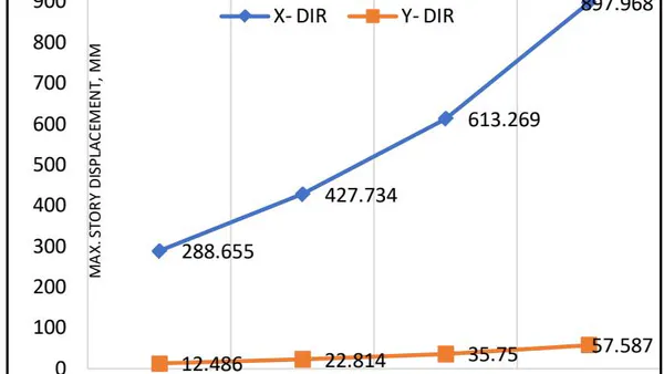
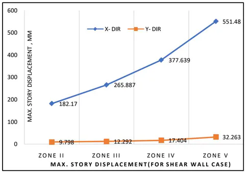
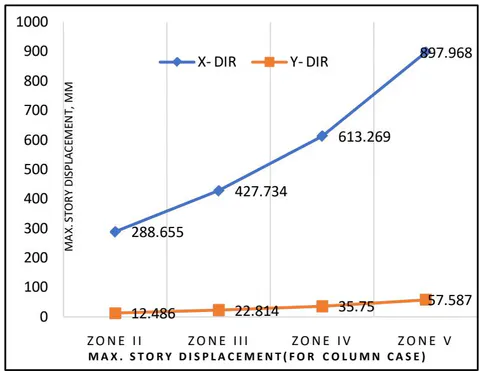
Maximum Story Displacement Defined as Displacement occurred at each story level, generally high rise/multi-storey/tall Buildings, has maximum storey displacements at top floors, as height increases story displacements increases. Following are the Result extractions from model done in Etabs 2021, for the story response- Max. Story displacement. This Parameter is being analyzed for Critical Load Combination is 1.5DL-1.5 Eqx.
| SUMMARY OF MAX. DISPLACEMENT | ||||
| CRITICAL CASE 1.5 DL-1.5EQX | ||||
| ON SHEAR WALL | ON COLUMN | |||
| X-DIR | Y-DIR | X-DIR | Y-DIR | |
| ZONE II | 182.17 | 9.798 | 288.655 | 12.486 |
| ZONE III | 265.887 | 12.292 | 427.734 | 22.814 |
| ZONE IV | 377.639 | 17.404 | 613.269 | 35.75 |
| ZONE V | 551.48 | 32.263 | 897.968 | 57.587 |
b) Max. Story Drift
Story Response - Maximum Story Drift Story Drift is defined as relative (Inter-storey) displacement between the stories. Higher Drift Causes the horizontal displacement of the story/building in the case of lateral forces application like earthquake and winds. Building sway laterally in case of higher drift occurred.
Total drift of th i floor Inter-storey drift of i floor
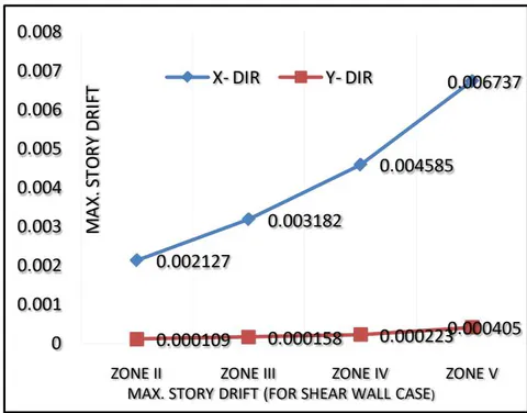
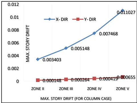
Following are the Result extractions from model we did in Etabs 2021, for the story response- Max. Story Drift. Followings are the tables and their graphs in eight cases, are formed for the analysis for critical case 1.5DL-1.5Eqx.
| SUMMARY OF MAX. DRIFT | ||||
| CRITICAL CASE 1.5 DL-1.5EQX | ||||
| ON SHEAR WALL | ON COLUMN | |||
| X- DIR | Y- DIR | X- DIR | Y- DIR | |
| ZONE II | 0.002127 | 0.000109 | 0.003403 | 0.000148 |
| ZONE III | 0.003182 | 0.000158 | 0.005148 | 0.000264 |
| ZONE IV | 0.004585 | 0.000223 | 0.007468 | 0.000419 |
| ZONE V | 0.006737 | 0.000405 | 0.011027 | 0.000655 |
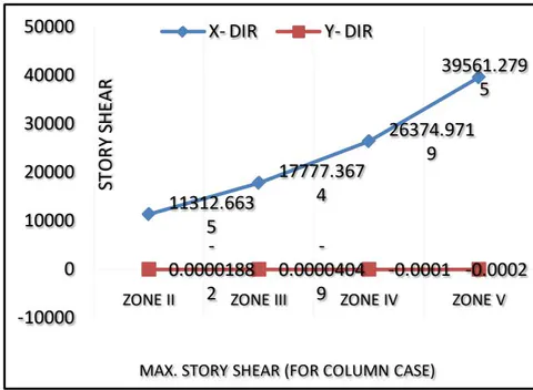
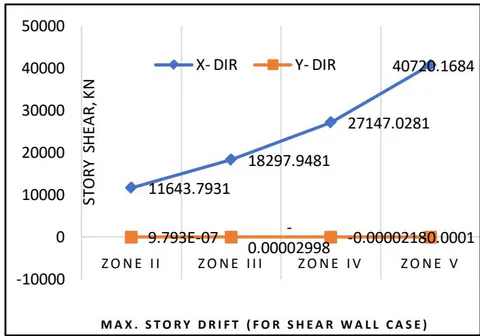
c) Story Shear
Story Response - Story Shear Defined as the Forces acting on each story of the building due to lateral forces like wind and earthquakes.
Building having lesser stiffness have lesser story shear on each level of building and vice versa.
Following are the Result extractions from model we did in E 2021, for the story response-Story Shear.
Followings are the tables and their graphs in eight cases, are formed for the analysis for critical case 1.5DL-1.5Eqx.
| SUMMARY OF STORY SHEAR | ||||
| CRITICAL CASE 1.5 DL-1.5EQX | ||||
| ON SHEAR WALL | ON COLUMN | |||
| X-DIR | Y-DIR | X-DIR | Y-DIR | |
| ZONE II | 11643.7931 | 9.793E-07 | 11312.6635 | -0.00001882 |
| ZONE III | 18297.9481 | -0.00002998 | 17777.3674 | -0.00004049 |
| ZONE IV | 27147.0281 | -0.0000218 | 26374.9719 | -0.0001 |
| ZONE V | 40720.1684 | -0.0001 | 39561.2795 | -0.0002 |
d) Overturning Moment
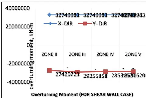
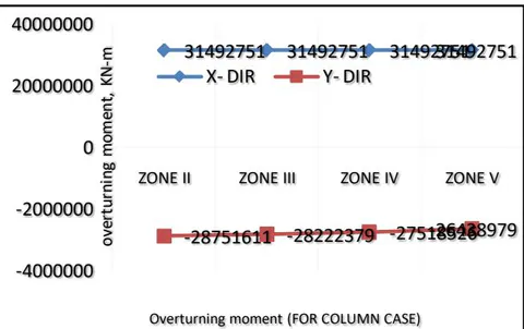
Story Response - Maximum Overturning Moments
Overturning moment defined as the Total moment of building with developed through Lateral forces applications.
Overturning moment in x- direction = Seismic Force in X-Dir x Height of building from N.G.L
Overturning moment in Y- direction = Seismic Force in Y-Dir x Height of building from N.G.L
Following are the Result extractions from model we did in E 2021, for the story response- Max. Overturning Moment.
This is nothing but the torsion generated over the building due to lateral forces.
Basically, this is the moment that turns building with the central axis due to forces causes due to lateral forces at each of the story.
Torsional rigidity can be seen if overturning moments are lesser in below cases.
Followings are the tables and their graphs in eight cases, are formed for the analysis for critical case 1.5DL-1.5Eqx.
Table 8: Summary of Overturning Moment
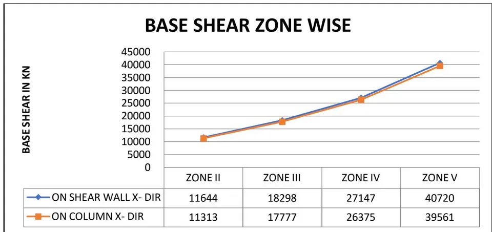
e) Base Shear
Base Shear is defined as Total Force act at foundation level or lowest level of building due Seismic Building Weight.
Base Shear = Seismic Weight of the Building x Design Horizontal Coeff.
Where,
is the outline flat seismic coefficient, which relies upon the seismic zone factor (Z), response reduction factor (R), importance factor (I), and the normal reaction speeding up coefficients . thus establishment relies upon the idea of soil (shake, medium or delicate soil site), characteristic span and damping of the structure. Followings are the tables and their graphs in eight cases, are formed for the analysis for critical case 1.5DL-1.5Eqx.
| Max. Base Shear in Shear Wall Case | Shear Wall Zone II | Shear Wall Zone III | Shear Wall Zone IV | Shear Wall Zone V |
| Critical Case | KN | KN | KN | KN |
| 1.5DL-1.5EQ+X | 11644 | 18298 | 27147 | 40720 |
| Max. Base Shear in Column Case | Column Zone II | Column Zone III | Column Zone IV | Column Zone V |
| Critical Case | KN | KN | KN | KN |
| 1.5DL-1.5EQ+X | 11313 | 17777 | 26375 | 39561 |
f) Max. Axial Force
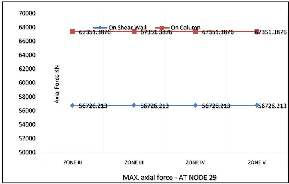
Followings are the tables and their graphs in eight cases, are formed for the analysis for critical case 1.5DL+1.5LL. At node no 29 in critical case, max. Individual axial force is found in all eight cases.
| On Shear Wall | On Column | % DIFFERENCE | ||
| MAX. FZ (AXIAL REACTION-KN) | ZONE III | 56726.213 | 67351.3876 | -19% |
| ZONE III | 56726.213 | 67351.3876 | -19% | |
| ZONE IV | 56726.213 | 67351.3876 | -19% | |
| ZONE V | 56726.213 | 67351.3876 | -19% |
g) Discussion on Results
Max. Storey Displacement- As the seismic zones increases, Maximum story displacement increases in both cases either Building Analyzed on shear wall or on columns, When Critical Load Combination found 1.5DL-1.5EQx, In Various Zones II, III, IV, V the max. Story displacement found , , , lesser Value in case of Building being analyzed on Shear wall respectively. Building's max. Story displacement is under allowable limit. As per IS 1893:2016).
Max. Storey Drift- As the seismic zones increases, Maximum story displacement increases in both cases either Building Analyzed on shear wall or on columns, When Critical Load Combination found 1.5DL-1.5EQx, In Various Zones II, III, IV, V the max. Story drift found , , , lesser Value in case of Building being analyzed on Shear wall respectively. Building's max. Story drift is under allowable limit. As per IS 1893:2016).
Story Shear- As the seismic zones increases, Story Shear increases in both cases either Building Analyzed on shear wall or on columns, When Critical Load Combination found 1.5DL-1.5EQx, In Various Zones II, III, IV, V the max. Story Shear found , greater Value in each zone, Building being analyzed on Shear wall respectively. Story Shear Found Greatest in Value on Ground floor.
Story Overturning Moment- As the seismic zones increases, No Change in Story Overturning Moment in both cases either Building Analyzed on shear wall or on columns, When Critical Load Combination found 1.5DL-1.5EQx, In Various Zones II, III, IV, V the max. Story Overturning Moment found , greater Value in each zone Building being analyzed on
Shear wall respectively. Story Overturning Moment Found Greatest in Value on Ground floor.
Base Shear- As the seismic zones increases, Base Shear increases in both cases either Building Analyzed on shear wall or on columns, When Critical Load Combination found 1.5DL-1.5EQx, In Various Zones II, III, IV, V the max. Base Shear found , greater Value in each zone, Building being analyzed on Shear wall respectively. Base Shear Found Greatest in Value on Basement Level.
Axial force/Reaction- As the seismic zones increases, No Change in Axial Force in both cases either Building Analyzed on shear wall or on columns, When Critical Load Combination found , In Various Zones II, III, IV, V the max. axial force found , lesser Value in each zone Building being analyzed on Shear wall respectively. At Column/Node No. 29 max. axial force Found.
V. CONCLUSION/SUMMARY AND FINDINGS
Based on the result obtained the following conclusions can be drawn by Etabs 2021.
Maximum Story Displacement found average lesser if Building Analyses over Shear Wall in comparison of as on Column.
Maximum Storey Displacement Found at 108m lvl. For critical case 1.5DL-1.5Eqx
Max. Storey displacements is min. In Zone II (Shear Wall case) is 182.17mm and maximum in Zone V (Column Case) is 897.968mm. This Building is Safe Up to Zone IV for Shear Wall Case and Safe up to Zone III for Column Case. (Refer Table no. 4.10)
As Inter Max. storey Displacements or Max. Story Drifts relates with Storey Displacements, Max.
- Storey Drift Found average lesser if Building Analyses over Shear Wall in comparison of as on Column.
Maximum Storey Drift Found at 46.9 m lvl. In each of Model Case, For critical case 1.5DL-1.5Eqx
Max. Storey Drift is min. In Zone II (Shear Wall case) is.00212 and maximum in Zone V (Column Case) is 0.011027. This Building is Safe Up to Zone IV for Shear Wall Case and Safe up to Zone II for Column Case. (Refer Table no. 4.19)
Storey Shear Found greater if Building Analyses over Shear Wall in comparison of as on Column, Which is Marginal.
Storey Shear Found Greatest in Value at Ground Floor Lvl. In each of Model Case, For critical case 1.5DL-1.5Eqx
Storey Shear is min. In Zone II (Column case) is 11312.6 kN and maximum in Zone V (Shear Wall Case) is 40720.17 kN. (Refer Table no. 4.28)
Storey Overturning moment Found greater if Building Analyses over Shear Wall in comparison of as on Column, Which is Marginal.
Storey overturning moment Found Greatest in Value at Ground Floor 0.00 m Lvl. In each of Model Case, For critical case 1.5DL-1.5Eqx
Storey overturning moment is min. In Column case is 31492751 kN-m and maximum in Shear Wall Case is 32749983 kN-m. (Refer Table no. 4.37) for Each Seismic Zone.
Base Shear Found greater if Building Analyses over Shear Wall in comparison of as on Column, which is Marginal.
Base Shear is min. in Zone II (Column case) is 11313 kN and maximum in Zone V (Shear Wall Case) is 40720 kN. (Refer Table no. 4.40), Which is Greatest in Value at foundation/Base Floor -5.2 m Lvl. In each of Model Case, For critical case 1.5DL-1.5Eqx.
Maximum Axial force/Reaction found Lesser if Building Analyses over Shear Wall in comparison of as on Column, at Node/Column No. 29, for Critical Case 1.5DL+1.5LL. (Refer Table no. 4.41)
Hence, If all above conclusion taken in the Consideration, Shear wall performs/behaves better than Column comparatively in case of tall Structure. To provide better safety against Maximum Story displacement, Maximum Story Drift, Story Shear, Maximum Overturning Moment, Base shear and Axial Reaction shear wall Configuration is Recommended to use.
For deliver more safety in the building in All Seismic Zone, Parametric Properties of Shear Wall can be improved.