

I. INTRODUCTION
Computer network borne out of the need to use personal computers for sharing information within an organization in the form of messages, sharing files, resources and so forth. Whether the organization is located in a small area like as in one building or spread over a large area, the need for networking the computers cannot be over emphasized. A university area network is an essential part of university system. A university network has several uses such as teaching, learning, result publishing, resource sharing, file sharing, communication, etc. The University Area Network design is about designing a topology of a network that is a LAN (Local Area Network) for a university in which various computers of different departments and buildings are set up so that they can interact and communicate with each other by interchanging data. To design a network for a University which connects various departments and buildings to each other's, it puts forward communication among them. One of the purpose of networking is to reduce isolated users. The systems should be capable of communicating with others and should provide the desired information. A simulation tool offers a way to predict the impact on the network of a hardware upgrade, a change in topology. So in this dissertation, a UANS network is designed using Cisco Packet Tracer. Cisco Packet Tracer (CPT) is multitasking network simulation software that can be used to perform and analyze various network activities such as the implementation of different topologies, selection of optimum path based on various routers, analysis of different network configurations [4]. This University Area Network Scenario is about designing a topology of a network that is Local Area Network (LAN) for a university area in which different department has some computers in different buildings set up their network so that they can interact and communicate with each other by interchanging data.
II. TECHNOLOGY TO BE USED
CCNA: Cisco discovered Cisco Certified Network Associate (CCNA) to identify and analyze the basic capability of the installation and maintenance of different size networks. This technology used for connecting various devices like routers, switches with each other for transferring and interchanging data. To contract a disciplined and trustworthy network is scalable too. Portability is one of the characteristics of this network application of the UANS.
III. BASIC ARCHITECTURE
IV. WORKING OF UANS
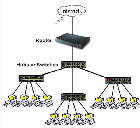
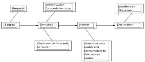
This University Area Networking Scenario is to provide a well-connected, secure, reliable, dependable communication among different departments. Several departments can simply split the required data without any problem and can exchange their data without going physically to them thus conserving time and energy.
V. REQUIREMENTS
The following section discusses the requirements related to the interfaces used to communicate with lots of data. These data combine clients, software interfaces and other hardware that permit the system to carry out its task.
a) User Interface
The requirements represent in this module describes the UANS interface. The requirements are picked up to the main characteristics provided by the system. The necessities always maintain the activities interconnected with the subheading characteristics.
b) Interface Formats
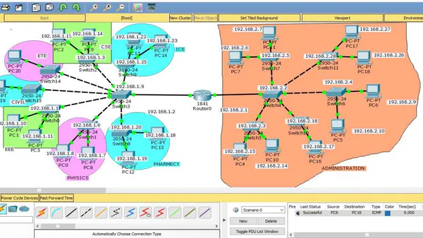
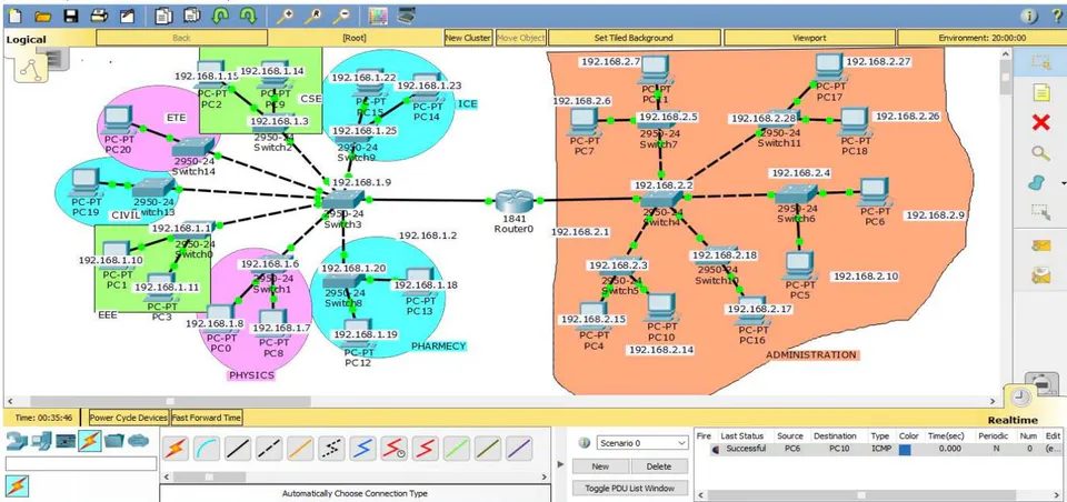
This screen displays the virtual topology designed for the university.
The network simulation, i.e. Cisco Packet Tracer (CPT) is simple, easy for implementation and straightforward.
It cultivates visual graphical user interface.
It will display twelve switches, different VLANs and one router interconnected with each other.
The Command Line Interface (CLI) is used for configuration.
The CPT allows the user to run the project on run time mode or simulation.
When the administrator clicks on any device, then the graphical user interface is open for the particular device.
c) System Interface
In this UANS, giving data to end device, a Graphical User Interface is needed and appear a login form to the authorized user. We can reset the password by the help of network administration. Whereas unauthorized user prohibits to access the network.
d) Hardware Interface
To run the simulator software (i.e. CPT) some basic hardware requirements are need. That are-
- RAM:512MB
CPU: Intel Pentium Dual core
Storage:500MB of free disk space
Display Resolution:800*600
Adobe Flash Player.
Recommended Hardware:
RAM: > 512 MB
CPU: Intel Pentium III 1.0 GHz
Display resolution: 1024 x 768
Storage: 300 MB free disk space
For run the module, the hardware requirements are:
12 Switches (Cisco 2950 switch)
1 Router (Cisco 1841 router)
Computer Systems (Generic)
One Computer system for server
Cross over cable
Straight through cable
e) Software Interfaces
The requirements required in the UANS are as follows:
Operating System: Microsoft Windows 7.
Adobe Flash Player.
Cisco Packet Tracer
f) Communication Interfaces
The system will execute over the university area network.
The system based on a client-server application where the server provide data services only.
| ADDRESS CLASS | VALUE IN 1 OCTET |
| A | 1-126 |
| B | 128-191 |
| C | 192-223 |
| D | 224-239 |
| E | 240-255 |
In the UANS is used IPv4. An IPv4 is of32 bits numbers. The address is written in dotted-decimal notation represent it X.X.X.X each octet divide by a dot. For UANS network the IP Address is used 192.168.0.0 with a subnet mask of 255.255.0.0. IP 192.168.0.0 is the class C address. IP address divide among various VLANs and ports for communication. The greater IP address is divide into small parts by using VLSM (Various Length Subnet Mask). VLSM is a method that categorized an IP address into a subnet and shares it according to the necessity of a network.
In Fig.3 show the complete diagram of University Area Network and it consists of router, switches and end devices. Here the different department's personal computers are connected with switch. IP address and subnet mask are assigned to all the departments and area of this UANS. IP Address of personal computer (PC):
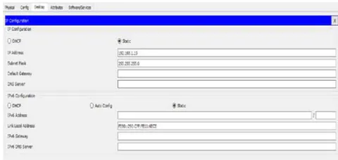
Table 2 shows the IP Addresses all PCs which are used in UANS network.
| PC | IP ADDRESS |
| PC-0 | 192.168.1.8 |
| PC-1 | 192.168.1.10 |
| PC-2 | 192.168.1.15 |
| PC-3 | 192.168.1.11 |
| PC-4 | 192.168.2.15 |
| PC-5 | 192.168.2.10 |
| PC-6 | 192.168.2.9 |
| PC-7 | 192.168.2.6 |
| PC-8 | 192.168.1.7 |
| PC-9 | 192.168.1.14 |
| PC-10 | 192.1682.14 |
| PC-11 | 192.168.2.7 |
| PC-12 | 192.168.1.19 |
| PC-13 | 192.168.1.18 |
| PC-14 | 192.168.1.23 |
| PC-15 | 192.168.1.22 |
| PC-16 | 192.168.2.17 |
| PC-17 | 192.168.2.27 |
| PC-18 | 192.168.2.26 |
| PC-19 | 192.168.1.52 |
| PC-20 | 192.168.1.53 |
switch>enable switch#config t Enter configuration commands. One per line. End with CNTL/Z. switch(config)#hostname s1 switch(config)#interface vlan1 switch(config-if)#IP address 192.168.1.1 255.255.0.0 switch(config-if)#no shut Fig. 4: Configuration of a switch
Table 3 shows the IP Addresses all switches which are used in the UANS network.
| SWITCH | IP ADDRESS |
| SWITCH-0 | 192.168.1.1 |
| SWITCH-1 | 192.168.1.6 |
| SWITCH-2 | 192.168.1.3 |
| SWITCH-3 | 192.168.1.9 |
| SWITCH-4 | 192.168.2.2 |
| SWITCH-5 | 192.168.2.3 |
| SWITCH-6 | 192.168.2.4 |
| SWITCH-7 | 192.168.2.5 |
| SWITCH-8 | 192.168.1.20 |
| SWITCH-9 | 192.168.1.25 |
| SWITCH-10 | 192.168.2.18 |
| SWITCH-11 | 192.168.2.28 |
| SWITCH-13 | 192.168.1.51 |
| SWITCH-14 | 192.168.1.50 |
Command Line Interface (CLI) for Router: Continue with configuration dialog? (yes/no) no Press RETURN to get started! Router>enable Router#config t Enter configuration commands, one per line. End with CNTL/Z. Router(config)#interface fa Router(config)#interface fastEthernet 0/0 Router(config-if)#ip address192.168.1.2 255.255.255.0 Router(config-if)#no shut %LINK-5-CHANGED: Interface FastEthernet0/0, changed state to up %LINK-5-UPDOWN: Line protocol on Interface FastEthernet0/0, changed state to up Router(config-if)#exit Router(config)#interface fastEthernet 1/0 Router(config-if)#ip address192.168.2.1 255.255.255.0 Router(config-if)#no shut %LINK-5-CHANGED: Interface FastEthernet0/0, changed state to up %LINK-5-UPDOWN: Line protocol on Interface FastEthernet0/0, changed state to up
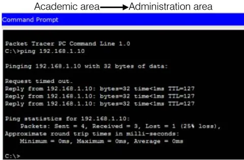
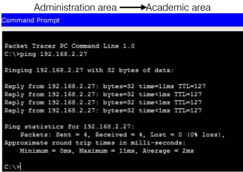
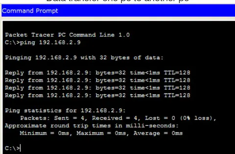
8.1 Ping Test: Network connectivity and communication can be tested using ping command, followed by the domain name or the IP address of the device (equipment) one wishes to verify connectivity. Two VLANs have been added to the existing network and the ping command was performed to verify if the devices connected to those VLANs are communicating with the rest of the nodes on the network. [2]
IX. CONCLUSION
In this paper, a UANS (University Area Network Scenario) that uses networking topology implemented with concepts like VLANs in a multiple area networks using Cisco Packet Tracer. VLANs have been used to logical UANS and with the aid of a router and switch configurations, data packet routed from one device to another. The procedures provide a design and approach for UANS using VLANs for an end to end IP network connectivity for next generation network architecture implementations. To design the network for UANS produces the substructure for all the service framework such as security of the network, wireless area network, operational efficiencies, virtual learning environments, and secure classrooms. Finally, the network foundation services such as switching, routing multicast, and high availability are giving for the UNAS.
X. FUTURE WORK
The configuration and specifications are for the initial prototype and can further be developed and additional functionality can be added to increase support and coverage.