## I. INTRODUCTION
The submerged arc welding technology is mostly used in the fabrication of industrial pressure vessels. To ensure the durability and safety in operation of products such as pressure vessels that can work at room temperature or high temperatures, ensuring good resistance in maintaining the high pressures that develop inside the vessels it is necessary that the welded joints have good mechanical properties.
The mechanical properties of the welded joints are mainly influenced by the applied welding regime, having as the main parameters the welding voltage, the intensity of the welding current and the welding speed. The welded joints found for the fabrication of pressure vessels are executed in 2 distinct ways, continuous longitudinal welding or continuous welding on the circumference.
The welded joints executed by the longitudinal welding method mostly support stretching loads, due to the pressures developed inside the pressurized vessels, having an effect of uniform stretching of the walls of the vessels. In the case of the welded joints executed on the circumference of the pressure vessels, the stresses that take place are generated by bending loads, the situation being presented in figure 1.
The pressurized vessels are usually made of two main parts, the first being the central cover made of a laminated steel sheet, rolled and closed by longitudinal welding which can be seen in figure 1, detail X. The other component is the cap, which is present on both ends, it is also made of laminated steel sheet, obtaining its shape by embossing, its connection with the central cover is made by circular welding on the exterior round contour. [1]


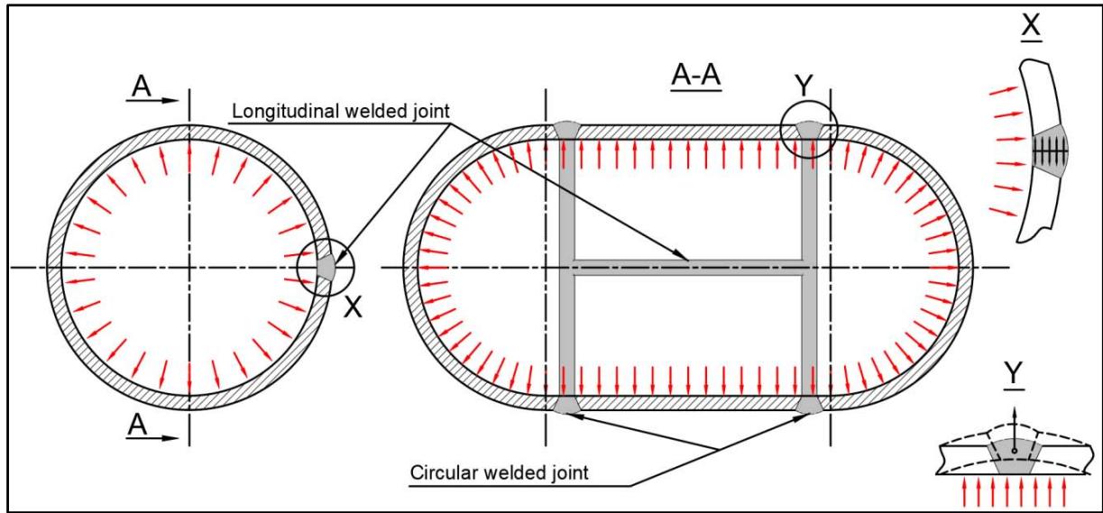 Figure 1: Pressure Vessel Joints and Stress Distribution [2]
In this paper the focus will be on determining the influence of the parameters of the welding regime on the bending strength of the welded seams using the technology of submerged arc welding on the P355 N pressure vessel steel from which the tank wagons for the transportation of petroleum products are made.
The effects of the parameters of the welding regime will be compared by means of the stress-deflection curves resulting from the testing of specimens for bending tests taken from welded seams using different variations of the 3 parameters under study. To carry out the experiments, a set of 4 specimens were taken for bending tests specific to each welding regime. The purpose of the experiments is to develop a statistic regarding the evolution of the bending strength characteristics of the welded seams depending on the welding regime parameters. The data obtained is processed for determining and compare trends in the evolution of changes in the bending resistance characteristics of the welded joints, data that can be used to optimize the welding process, improving aspects regarding productivity and quality.[3][4]
## II. EXPERIMENTAL MATERIAL AND METHODS
To carry out the experiments, welded samples were made from 6 mm thick plates joined by butt welding made from P355 N steel, standard SR EN 10216-3:2003. From these samples, bending test specimens were taken, with dimensions of $250 \times 25 \times 6$ with the welded joint arranged in the middle of the specimen. The welded samples were made in the industry on a semi-automatic submerged welding machine, the welds being executed respecting the following process characteristics.[5][6]
- Welding procedure: Welding under flux with wire electrode, codification 121, according to standard EN ISO4063. [7]
- Joint type:
- Butt welding with full penetration, codification BW, according to standard SR EN 287-1. [8]
- Welding with root support, codification mb, according to standard SR EN 287-1. [8]
- One-pass welding, codification sl, according to standard SR EN 287-1
- Welding position: Horizontal, codification PA, according to standard SR EN ISO 6947. [9]
The filler material used in the welding process is intended for submerged arc welding of a carbon steel, being a molybdenum-alloyed copper carbon steel, found in the form of a round section electrode of 3, 2 mm in diameter. The manufacturer of the electrode classifies it in the material catalogs as type OK Autrod 12.24. [10]
The material that constitutes the protective environment of the electric arc and the molten weld is a layer of granular flux. Classified by the is manufacturer as type OK flux 10.47, being deposited on the welding joint with an advance before the electrode and later being collected by suction after the passing of the electrode, to be recirculated through the deposition installation which creates a thick layer of approximately $25\mathrm{mm}$. [10]
Figure 2 shows an image of the welding process, it can be seen that the electrode is plugged by the flux layer during welding process and the way the flux is deposited and collected during the welding process. The plate on which the weld is made contains 2 samples from which the specimens were taken for the bending test.
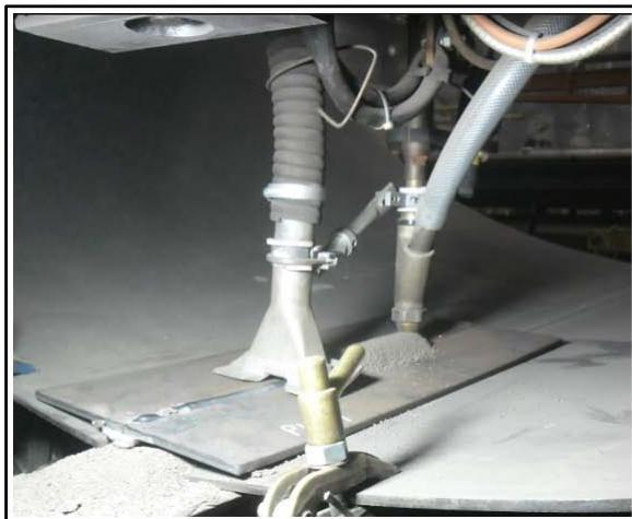
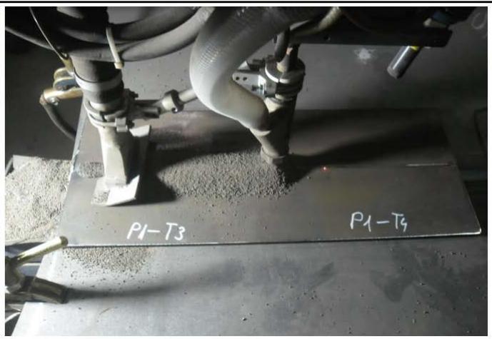 Figure 2: The Process of Submerged ARC Welding Samples in the Industry
From one welded sample, 4 bending testing specimens were obtained, each sample being welded with a different welding regime. The processing of the specimens was carried out by the mechanical process of cutting the sample sheet with the guillotine, in order to avoid the thermal effects that other mechanical cutting processes have.
The standard welding regime used in the industry is the reference base to which the other welding regimes subject to the study will be related, as well as their specific strength characteristics. The standard welding regime parameters are the welding voltage 33 V, welding current intensity 480 A and welding speed 60 cm/min.
The structure of the welding regimes under study is composed of 3 main parameters each having 3 stages of variation to determine a trend of the evolution of the strength characteristics depending on the value of the parameters involved. The classification of welding regimes subjected to the study is reproduced under the following structure:
### 1. Welding regimes that involve the variation of welding voltage:
- 22V, 480A, 60 cm/min
- 30V, 480A, 60 cm/min
- 38V, 480A, 60 cm/min
2. Welding regimes that involve the variation of welding current intensity:
- 33V, 300A, 60 cm/min
- 33V, 500A, 60 cm/min
- 33V, 700A, 60 cm/min
3. Welding regimes that involve the variation of welding speed:
- 33V, 480A, 25 cm/min
- 33V, 480A, 75 cm/min
- 33V, 480A, 125 cm/min
The testing of the specimens took place on an A009 (TC100) universal testing machine of $100\mathrm{kN}$ capacity, using a device with two support rollers on which the specimen was placed and pressed onto the weld bead with a rounded prism. In figure 3, images from the testing are shown, where it can be seen how the bending prism acts on the sample.
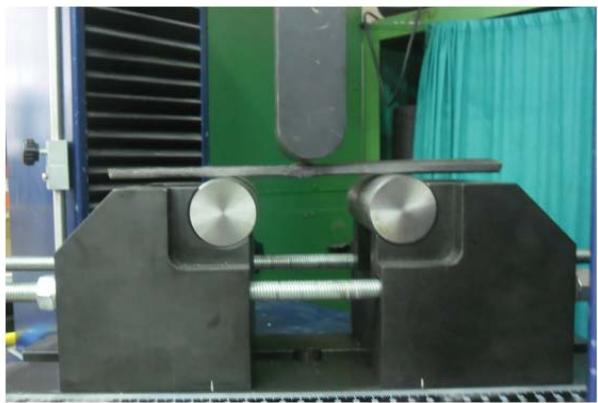
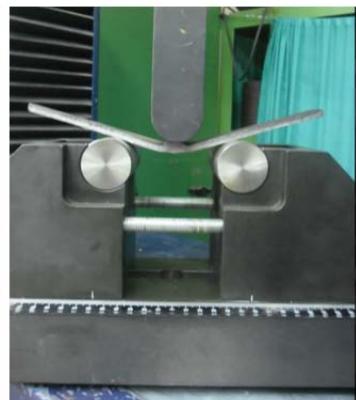 Figure 3: The Bending Test Process
The distance between the centre of the support rollers during testing was $120\mathrm{mm}$, the rollers being 40 mm in diameter. The prism pressing on the sample had a radius of $20\mathrm{mm}$ in the pressing area. Figure 4 shows an image of how it was installed the test specimen in the test device. The testing of a specimen continues until the weld seam cracks or until the specimen is completely bent. The tests took place with a pressing speed of $50\mathrm{MPa/s}$, the data acquired by the machine's data acquisition system are the displacement of the mobile beam in which the pressing prism is mounted, and the force applied throughout the experiment. [11]
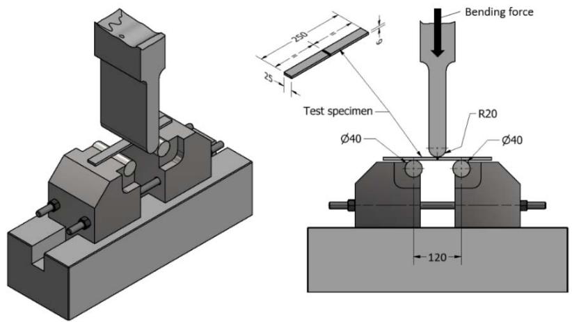 Figure 4: Installation of the Specimen in the Bending test Device
## III. DATA ANALYSIS AND INTERPRETATION
As a result of the experiments, a set of stress-deflection curves were obtained, these being 4 for each welding regime under study, from which a representative curve was extracted for each group. Figure 5 represents a comparison between these stress-deflection curves specific to each welding regime that was involved in the study.
It can be seen the major difference between the sets of curves, a group that aims to study the influence of a specific parameter on the behaviour of welded joints, subjects to bending loads, is made up of 3 stress-deflection curves that are represented with the same colour, the line type of the curve represents the stage of variation for the respective parameter.
Curves with a more pronounced gauge reflect the presence of better mechanical properties, such as superior toughness and ductility compared to curves with a smaller coverage area on the graph that show a fragility of the welded joint.
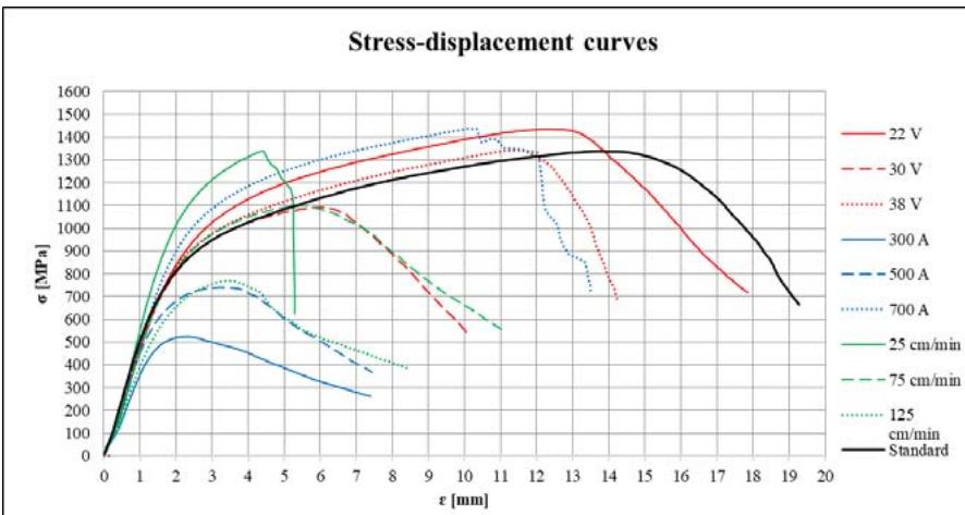 Figure 5: Stress-Strain Curves
Analysing the graph, it can be observed that the use of a welding voltage of $22\mathrm{V}$ presents a situation of stress-strain curves with superior mechanical properties, it can also be observed a trend of involution of the curve which is more and more pronounced once with the increase of the welding voltage from $22\mathrm{V}$ to 38. It can also be noted that the use of a welding regime with an amperage of 300 A presents the worst situation presented by the graph, having the lowest curve in terms of the maximum stresses developed in the welded joint.
A centralized situation of the resistance characteristics obtained after the bending tests is presented in tables 1, 2 and 3. The main characteristic followed for determining the bending resistance capacity of welded joints is the maximum bending force.
Using the maximum bending breaking force in formula (1) results in the value of the maximum bending stress developed during the bending test, this value largely depending on the geometry of the welded seam also.
$$
\sigma_ {m a x} = \frac {3 \cdot F \cdot L}{2 \cdot w \cdot h ^ {2}}
$$
$F$ -load at span center,
$L$ -distance between supports,
$w - width$ of specimen,
$h^2$ - thickness of specimen
Table 1: Strength Characteristics Collected from Stress-Strain Curves
<table><tr><td>Parameters</td><td>22 V</td><td>30 V</td><td>38V</td><td>U.M.</td></tr><tr><td>Maxim bending force</td><td>9,74</td><td>7,55</td><td>9,84</td><td>kN</td></tr><tr><td>Maxim displacement</td><td>29,21</td><td>10,04</td><td>14,27</td><td>mm</td></tr><tr><td>Maxim bending stress</td><td>1527,60</td><td>1092,17</td><td>1342,66</td><td>MPa</td></tr><tr><td>Displacement at maxim bending stress</td><td>19,23</td><td>6,07</td><td>11,47</td><td>mm</td></tr><tr><td>Bending energy</td><td>26330,60</td><td>5659,37</td><td>10305,71</td><td>KJ</td></tr></table>
Table 2: Strength Characteristics Collected from Stress-Strain Curves
<table><tr><td>Parameters</td><td>300 A</td><td>500 A</td><td>700 A</td><td>U.M.</td></tr><tr><td>Maxim bending force</td><td>3,47</td><td>5,60</td><td>10,85</td><td>kN</td></tr><tr><td>Maxim displacement</td><td>7,40</td><td>8,97</td><td>21,76</td><td>mm</td></tr><tr><td>Maxim bending stress</td><td>523,30</td><td>832,55</td><td>1597,01</td><td>MPa</td></tr><tr><td>Displacement at maxim bending stress</td><td>2,38</td><td>3,79</td><td>16,71</td><td>mm</td></tr><tr><td>Bending energy</td><td>1842,80</td><td>3782,13</td><td>27761,95</td><td>KJ</td></tr></table>
Table 3: Strength Characteristics Collected Ffrom Stress-Strain Curves
<table><tr><td>Parameters</td><td>25 cm/min</td><td>75 cm/min</td><td>125 cm/min</td><td>U.M.</td></tr><tr><td>Maxim bending force</td><td>9,13</td><td>7,60</td><td>5,13</td><td>kN</td></tr><tr><td>Maxim displacement</td><td>5,29</td><td>11,10</td><td>8,44</td><td>mm</td></tr><tr><td>Maxim bending stress</td><td>1338,03</td><td>1098,98</td><td>769,41</td><td>MPa</td></tr><tr><td>Displacement at maxim bending stress</td><td>4,42</td><td>5,52</td><td>3,51</td><td>mm</td></tr><tr><td>Bending energy</td><td>3425,49</td><td>6144,46</td><td>2925,77</td><td>KJ</td></tr></table>
All the data found in tabular form were regrouped for an easier analysis in figure 6 in the form of a radar graph, highlighting the evolution of the strength characteristics depending on the welding regimes used. Analysing the radar graph, there are 2 welding regimes for which all the strength characteristics have higher values than those specific to the standard welding regime. The standard welding regime that are represented by the following values:
- Maxim bending force $9,35 \mathrm{kN}$
- Maxim displacement $19,28\%$
- Maxim bending stress 1337,7 MPa.
- Displacement at maxim bending stress force 13.85 mm.
- Bending energy force increases from $20957.6 \mathrm{~kJ}$.
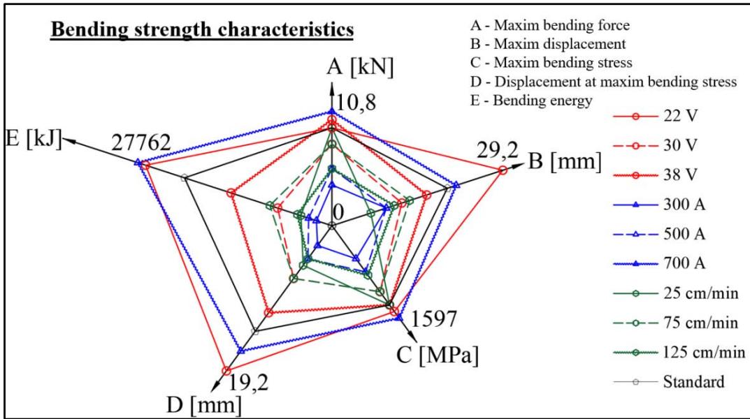 Figure 6: Evolution of Strength Characteristics Collected from Stress-Strain Curves
The welding regime for which the 22 V welding voltage is representative shows the following increases in resistance characteristics compared to the standard welding regime:
- Maxim bending force 9,74 kN resulting an increase of $0.39 \mathrm{kN}$, signifying a progression of $4,2\%$
- Maxim displacement $29.21\%$ resulting an increase of $9.93\%$, signifying a progression of $51.5\%$
- Maxim bending stress 1527,6 MPa resulting an increase of 189,9 MPa, signifying a progression of $14.2\%$
- Displacement at maxim bending stress force 19,23 mm resulting an increase of $5,38 \mathrm{~mm}$, signifying a progression of $38.8\%$.
- Bending energy 26330,6 kJ resulting an increase of 5372,9 kJ, signifying a progression of $25.6\%$
The second welding regime that has better bending strength characteristics than the standard one is the welding regime were the intensity of the electric arc was 700A, for which the values are:
- Maxim bending force 10,85 kN resulting an increase of 1,5 kN, signifying a progression of $16\%$
- Maxim displacement $21,76\%$ resulting an increase of $2,48\%$, signifying a progression of $12,8\%$
- Maxim bending stress 1597,01 MPa resulting an increase of 259,31 MPa, signifying a progression of $19.4\%$
- Displacement at maxim bending stress force 16,71 mm resulting an increase of $2,86 \mathrm{~mm}$, signifying a progression of $20.6\%$.
- Bending energy 27761,9 kJ resulting an increase of 6804,3 kJ, signifying a progression of $32.5\%$
## IV. CONCLUSIONS
As a main conclusion it could be said that 2 welding regimes with better strenght characteristics than those of the standard welding regime were identified and this are:
- 33V, 700A, 60 cm/min
- 22V, 480A, 60 cm/min
The maximum bending force recorded is specific to the welding regime 33V, 700A, 60 cm/min with the value of 10,85 kN resulting an increase of 1,5 kN, signifying a progression of $16\%$ comparing to the standard welding regime maximum bending force.
The maxim displacement is found within the welding regime o 22V, 480A, 60 cm/min with the value of 29, $21\%$ resulting an increase of $9.93\%$, signifying a progression of 51, $5\%$ comparing with the standard welding regime maxim displacement.
The maxim bending energy force is specific for the welding regime 33V, 700A, 60 cm/min and has a value of 27761,9 kJ resulting an increase of 6804,3 kJ, signifying a progression of 32,5% comparing to the standard welding regime bending energy.
The optimal welding regime being considered 33V, 700A, 60 cm/min.
Generating HTML Viewer...
References
13 Cites in Article
Dennis Moss (2004). Design of Vessel Supports.
G Ghanbari,M Liaghat,A Sadeghian,A Mahootchi,I Sokouti,R Heidary,M Mohammadi,A Ansarifard,M Seraj (2011). MINOR DEFECT EVALUATION PROCEDURE.
Cioroagă Bogdan- Dorel,Emanoil Linul,Cioatăvasile George,Dascăl Amalia (2023). The Influence of Submerged arc Welding Parameters on Bending Strength of Pressure Vessel Steel P355 N.
Ciofu Iurie,Niţulenco Tatiana,Bolunduţ Ioan-Lucian,Alexei (2012). Studiul şi ingineria materialelor.
Nicolae Joni,Nicolae Trif (2005). Sudarea robotizată cu arc electric, ediţia a 2-a.
European standard EN 10027-1:2005, Designation systems for steels -Part 1: Steel names.
(null). Seamless steel tubes for pressure purposes. Technical delivery conditions.
(null). Welding and allied processes. Nomenclature of processes and reference numbers.
European standard SR EN 287-1:2011.
(2011). Welding and allied processes - Welding positions.
(null). Specification for electrode wires and fluxes for the submerged arc welding of austenitic stainless steels based on weld metal composition.
N Surya,Dale Patnaik,Hopkins (2004). Strength of Material: A New Unified Theory for the 21st Century.
The Influence of Submerged Arc Welding Parameters on Bending Strength of Pressure Vessel Steel P355 N.
No ethics committee approval was required for this article type.
Data Availability
Not applicable for this article.
How to Cite This Article
Cioroagă Bogdan-Dorel. 2026. \u201cThe Influence of Submerged Arc Welding Parameters on Bending Strength of Pressure Vessel Steel P355 N\u201d. Global Journal of Research in Engineering - A : Mechanical & Mechanics GJRE-A Volume 23 (GJRE Volume 23 Issue A4): .
Explore published articles in an immersive Augmented Reality environment. Our platform converts research papers into interactive 3D books, allowing readers to view and interact with content using AR and VR compatible devices.
Your published article is automatically converted into a realistic 3D book. Flip through pages and read research papers in a more engaging and interactive format.
Our website is actively being updated, and changes may occur frequently. Please clear your browser cache if needed. For feedback or error reporting, please email [email protected]
Thank you for connecting with us. We will respond to you shortly.