
I. INTRODUCTION
The unipolar electric motor is a kind of DC electric machines. Contains a conductive disk, a constant magnetic field parallel to the axis of rotation of the disk, the 1st collector on the axis of the disk and the 2nd collector at the edge of the disk [1].
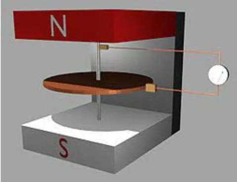
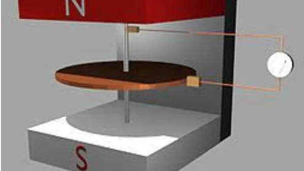
In Fig.1 the operating principle of unipolar engine is shown. If there is a conducting disk, located in magnetic field, then during the supplying stress on the axis of disk and on its edge through the disk flows current, which leads to its rotation. This rotation is caused by the influence of Lorentz force on the moving charges.
The first unipolar engine, the wheel of Barlow, created Peter by Barlow, after describing him in the book "study of the magnetic attractions", published in 1824.
Barlow's wheel was two copper gears, which are located on one axis. As a result interaction of current, passing through wheels, with the magnetic field of permanent magnets, wheels they revolve. Barlow explained that with change in contacts or position of magnetic poles the replacement of the direction of rotation of wheels to the opposite occurs. Barlow's engine in the inverted version presents direct-current generator.
It is evident from semy of generator that it contains two brushes, one of which tert against the axis engine, and the second of tert against the external rim disk. The presence of two brushes worsens the parameters of engine, since they rapidly are worn out.
UNIPOLAR GENERATOR
In sharkopodshipntke during its rotation galvanic contact between the external and internal rim ensure the moving balls or rollers. This fact can be used for creating unipolar genratora, in which there are no brushes. For this slebuet to use composite bearing, as shown in Fig. 2
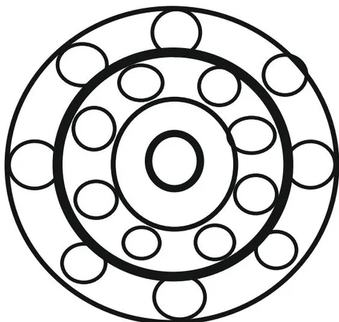
Composite bearing consists of two bearings of those inserted in each other, when the diameter of the external rim of inner bearing is equal to the diameter of the internal rim of outboard bearing, and they are combined. In the figure the combined rims they are shown by heavy line and present united cartridge clip.
During the rotation of this cartridge clip the balls will move in one direction, while the external cartridge clip of outboard bearing and the internal cartridge clip of inner bearing they will remain fixed.
In this case moving of ball or the rollers present the moving disk of unipolar generator, if we with one or from its two sides place permanent magnets. In this case the fixed cartridge clip of outboard bearing and the fixed internal cartridge clip of inner bearing are slip rings.
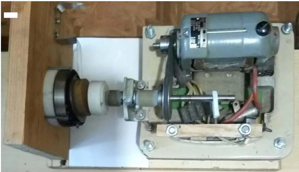
Experimental layoutthe generator examined it is represented in Fig. 3. In it they are used two inserted in each other of bearing, under which they are located six samarium-cobalt magnets, located symmetrically relative to rotational axis.
III. CONCLUSION
Application in the unipolar engines of samarium-cobalt magnets opens the new prospects of creating the engines with the large rotational moment, since. such magnets possess the great magnetic field, which cannot they will reach in other magnets. However, the creation of engines are connected with the need of using the brushes, friction against the external rim of the revolving disk and against its axis. Since the speed of rotation of the rim of disk is great, brushes rapidly are worn out, what is an essential drawback in this construction. In the article is represented the construction and the experimental layout of the unipolar generator, in which there are no brushes. This is achieved by the use of two ball bearings of those inserted in each other.
- Тамм И. Е. Основы теории электричества. Учебное пособие для вузов. – М. Наука. Гл. ред. Физ. Мат. лит. 1960.- 504 с.