## I. INTRODUCTION
Cancerous tumors are treated with radiotherapy by a specific dose of radiation. It is impossible for $100\%$ of the supplied radiation to be deposited in the tumor due to the physics principles governing radiation dose deposition in a medium. Therefore, radiotherapy aims to treat cancer with a therapeutic dose while keeping the amount to the nearby healthy tissues within clinically tolerable bounds. Target localization and organ-at-risk (OAR) sparing are being improved by ongoing research and development focusing on using fewer resources. Volumetric Modulated Arc Therapy (VMAT), commonly administered using a linear accelerator, was implemented, significantly advancing in the past ten years [1]. An intensity-modulated radiotherapy (IMRT) method involves dynamically adjusting the radiotherapy treatment beam aperture to create a final beam of varying intensity. This technique can be done for several beams at different gantry angles, resulting in a dose distribution throughout the patient that better adheres to the treatment goal (than a static beam) and better spares nearby OARs. Modern IMRT requires inverse planning techniques since they automatically tune dose distributions by adjusting the photon fluence in the radiation fields [2].
IMRT fields are delivered using MLCs that move while the beam is offered to change the beam aperture's shape continuously. With the MLC motions, the LINAC's dose rate is coordinated. The MLC movements and LINAC dose rate are coordinated to provide the necessary two-dimensional beam intensity fluence. Karl Otto first developed VMAT, which more recently included the IMRT principles (2008). VMAT uses a continuous rotating gantry arc for delivery instead of IMRT, which uses a series of discrete fixed gantry angles because the MLC and dose rate are regulated. The VMAT approach alters LINAC's requirements to give the treatment. The LINAC's performance is under additional stress by these requirements, which include changing gantry speed, gantry angle-dependent dose rate modulation, and more complex MLC motions [2]. As a result, VMAT-specific QA systems must be created to check that the planned dose distributions match those that were delivered and to assure delivery that is dependable, stable, and reproducible [2, 3]. During delivery, primary control is dictated by the gantry speed. The large mass of the treatment head makes this the most challenging component to modulate and control rapidly and accurately. When less than approximately 1.8 MU/deg is required, the gantry will move at maximum speed, but the dose rate will be dropped below 600 MU/min. When a more significant MU/deg rate is delivered, the maximum dose rate will be applied, and the gantry speed will slow down [4]. LINAC Quality Assurance (QA) testing is typical practice in radiation departments for guaranteeing LINAC performance. LINAC QA procedures typically rely on established best practice guidelines. The American Association of Physicists in Medicine (AAPM) TG-142 report [5] and AAPM Medical Physics Practice Guideline 8(a) are recent examples of such protocols [6]. The AAPM released guidelines for the delivery, treatment planning, and clinical application of IMRT in 2003 [7]. The AAPM released two task group reports in 2009 pertinent to IMRT and VMAT QA. The first, AAPM TG-142 [8], offered overarching guidelines for LINAC quality assurance [9].
Modern radiotherapy system is very sophisticated and requires quality assurance randomly. Nevertheless, due to the enormous patient load in a center, physicists and dosimetrists cannot set up QA equipment for daily checking of doses and machine parameters. So it required a quick setup system for equipment, essential parameters checkups, and patient plan verification. In 1990, a radiotherapy machine company introduced an Electronic Imaging system for checkup patients positioning [18]. After an era, they developed Electronics Imaging System called EPID. Modern EPID systems have an amorphous silicon-based detector for the patient imaging system, radiotherapy plan verification systems, and machine-specific QA systems. Task Group-58 (AAPM) published a report where they informed details use of EPID. The goals of this research work are:
1. Calculation of the Transmission Factor for specific field size and DLG using conventional and EPID-based observation.
2. Comparison of EPID-based results with other protocols and institutional standards.
### a) MLC Transmission
A radiation measurement has been performed with open and closed MLC for a $10 \times 10 \mathrm{~cm}^2$ field at $5 \mathrm{~cm}$ depth, SSD = 95cm; the ratio of these measurements is the transmission factor. We made the appropriate position of the slabs of solid water phantom with the dedicated hole for the Iso-Center above $5 \mathrm{~cm}$ of thickness to consider backscatter. A Farmer-type chamber was fixed in the solid phantom dedicated hole, and the cable of the chamber was set on the couch. The solid water phantom was aligned and made centered using the field light of a $30 \times 30 \mathrm{~cm}^2$ field. We mounted slabs for a thickness of $5 \mathrm{~cm}$ (chosen depth for the measurement) on the slab housing the detector. We set the SSD at $95 \mathrm{~cm}$, and the chamber position was in SAD at $100 \mathrm{~cm}$. We took data in block field size using Leaf Bank A and B. In QA mode, we opened the TPS plan, which we had prepared previously and took data for MLC Bank A ( $R_{\mathrm{TA}}$ ) and B ( $R_{\mathrm{TB}}$ ), respectively.
By the equitation below, the transmission factor was determined using EPID. In that case, SAD was fixed at 100 cm or SSD at 95 cm from the EPID with a 5cm build-up.
$$
Transmission Factor, R_T = \frac{R_{TA} + R_{TB}}{R_{Open}}
$$
### b) Dosimetric Leaf Gap (DLG)
Due to the round shape of the leaf edge and the use of the leaves in a dynamic way, a dosimetric gap is created between them for the movement of the leaves during IMRT and VMAT treatment. We will quantify this gap using EPID in this research. A pictorial representation of transmission through the rounded end of the MLC leaf is shown in Figure 1, illustrating that both the optical field size and DLG constitute a radiation field [10].
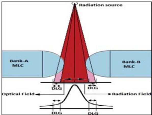 Figure 1: Transmission through the rounded-end of MLC leaf illustrating that both the optical field size and DLG constitute a radiation field [10].
Linear regression was performed using the acquired dose values and the related gap widths to evaluate the dynamic MLC fields with gap widths ranging from 0 to $20\mathrm{mm}$. The intercept of the regression line was the DLG.
We continued the remaining fields for the preliminary plan in QA mode using the same experimental configuration for the MLC transmission: 7 fields with various gap sizes (2, 4, 6, 10, 14, 16, and 20 mm, respectively). The dose values from the electrometer display were read and recorded in an Excel file for each field. Each value was corrected while taking the RT contribution of the transmitted doses. Then we performed linear regression with the computed $\mathrm{Rg}_{\mathrm{T}}$ and the associated gap widths. The intercept of the linear extrapolation is the DLG (dose value corresponding to gap width $= 0$ mm). We measured the reading from the moving gap $(\mathsf{R_g})$. We used 2 to 20 mm moving gap fields.
$$
R _ {g, T} = R _ {T} \left(1 - \frac {R _ {g}}{1 2 0}\right). \tag {2}
$$
We calculated the corrected gap reading for each gap, g, which is defined as
$$
R _ {g ^ {\prime}} = R _ {g ^ {-}} R _ {g, T} \dots \tag {3}
$$
## II. MATERIALS AND METHOD
The tools and equipment used in this study: integrated Electronic Portal Imaging Device (EPID), Farmer-Type Ionization Chamber, Electrometer, Eclipse TPS Version 16.0.1 software.
### a) Electronic Portal Imaging Device (EPID)
A 2D radiation detector integrated with the LINAC and used as a detector for both LINAC and patient-specific QA for IMRT/VMAT is called an EPID. Every time a patient is treated, the EPID is intended to assess their alignment with the radiation field [16]. Amorphous silicon-based active matrix flat panels are the now-standard EPID type (a-Si). In a 2D array, each photodiode is a single pixel that transforms incident light into an electric charge that a transistor uses to regulate signal reading [11].
Amorphous silicon EPID typically has thousands of faulty pixels (1%) in addition to the dark and flood field calibrations because of manufacturing restrictions [12]. These are adjusted by giving them the average value of the nearby pixels. Lastly, the EPID image grey scale is calibrated to LINAC Monitor Units under reference conditions for Varian patient-specific QA applications like Portal Dosimetry. The use of the Calibration Units (CU) calibration, also referred to as the dosimetry calibration on the VitalBeam LINAC, is accomplished by using the mean grey scale of an EPID image with a Region-of-Interest mean value at the central axis of 100MU under reference conditions and a designated CU value to provide a correction factor to the grey scale for the following reasons: subsequent images.
For use in dynamic treatments like IMRT and VMAT, the MLC has been the most often researched LINAC component with QA tests employing an EPID [13]. Other LINAC parts undergoing EPID testing include physical and dynamic wedges [14], gantry angle, asymmetric jaw alignment, and x-ray.
Using the Eclipse TPS, a QA plan was created to determine the transmission factor and the DLG. According to that plan, radiation was exposed to the EPID in QA mode. The MLC transmission and DLG of the machine were determined by analyzing the EPID based predicted integrated images. After the analysis, the information was processed, and the acquired data from the study were compared to VARIAN Machine Protocol and with some published data from various renowned international journals.
This thesis aims to determine how easily we can perform LINAC machine quality assurance using EPID or other array system diode-based QA devices. We tried to evaluate the DLG using EPID. The EPID system must first be configured to make it functional and usable. In the VARIAN VitalBeam Machine, the Portal Dose Image Prediction (PDIP) algorithm is usually used. Most radiotherapy centers perform Anisotropic Analytical Algorithms (AAA) to calculate the volume dose in the planning system of the LINAC machine. Some centers also use the AcurosXB algorithm. After installing a new LINAC machine, the acquired depth dose and beam profile data have been inserted into the TPS to configure it, making the machine fully commissioned and prepared for further treatment. The same data are also used to configure the PDIP.
### b) Farmer-Type Ionization Chamber
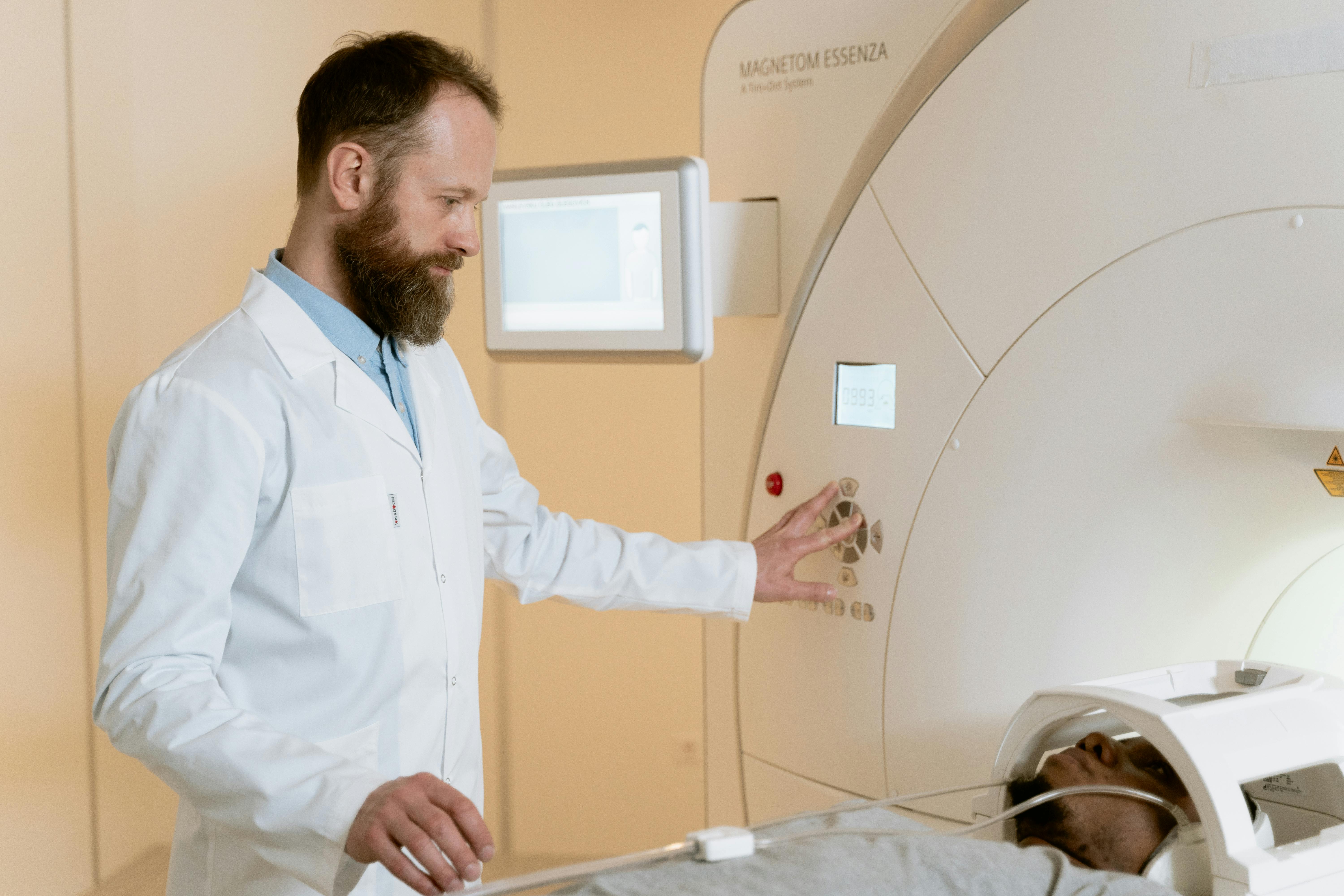
The standard for output measurement is placing an ionization chamber like IBA FC65-P 0.6cc Farmer type chamber, positioned at $5\mathrm{cm}$ depth in a solid water phantom at $100~\mathrm{cm}$ SSD. A Strontium source was used to examine the chamber response's consistency and to compare it to other Farmer-type chamber responses. The chamber response was then tracked back to the secondary standards laboratory. A solid water phantom setup with a Farmer-type ionization chamber is shown in Figure 2.
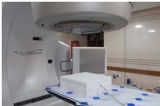 Figure 2: Solid water phantom setup with Farmer-type ionization chamber.
### c) The Linear Regression
Linear regression is a very suitable tool for predictive analysis. It is generally used for forecasting an effect, forecasting a trend and determining the predictor's strength linearly. The formula defines the simplest form of the equation of linear regression
$$
y = b x + c. \tag {4}
$$
Where,
$y =$ the estimated score of the dependent variable, $c =$ constant,
$b =$ regression co-efficient and
$x =$ the independent variable score.
### d) Transmission and DLG Measurement from Ionization Chamber Based Data
Measurement data for MLC transmission and DLG were tabulated in Table 1 using a standard $10 \times 10$ cm2 field size & 100 MU delivered for each energy and similar dose rates. SSD and SDD were 95 cm and 100 cm, respectively. IBA FC65-P ionization chamber and IBA Dose-1 electrometer were used. All of the data reading units were in nC charge.
Table 1: Ionization Chamber-Based Measurements for MLC Transmission and DLG. All of the data reading units are in nC charge reading. $(R_{\mathrm{open}} = \mathrm{Open~Field~Charge~Reading~with~Jaw~Setting~}10x10\mathrm{cm}^2$ and MLC fully open, $R_{T,A} =$ Transmission Reading for MLC Bank-A and $R_{T,B} =$ Transmission Reading for MLC Bank-B and Gap $=$ MLC Gap with Jaw Setting $10\times 10\mathrm{cm}^2)$
<table><tr><td>Energy</td><td>\(R_{Open} \)</td><td>\(R_{T,A} \)</td><td>\(R_{T,B} \)</td><td>Gap 2mm</td><td>Gap 4mm</td><td>Gap 6mm</td><td>Gap 10mm</td><td>Gap 14mm</td><td>Gap 16mm</td><td>Gap 20 mm</td></tr><tr><td>6 MV</td><td>1.865</td><td>0.0272</td><td>0.0272</td><td>0.0731</td><td>0.1038</td><td>0.1339</td><td>0.1950</td><td>0.2562</td><td>0.2870</td><td>0.3481</td></tr><tr><td>10 MV</td><td>2.040</td><td>0.0348</td><td>0.0346</td><td>0.0874</td><td>0.1209</td><td>0.1535</td><td>0.2204</td><td>0.2871</td><td>0.3207</td><td>0.3874</td></tr></table>
A graphical representation for DLG using solid water phantom with Farmer-type ionization chamber for 6MV and 10MV photons is shown in Figure 3 and Figure 4, respectively.
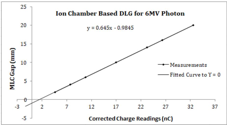
Figure 3: Graph for DLG calculation using solid water phantom with Farmer type ionization chamber for 6MV photon
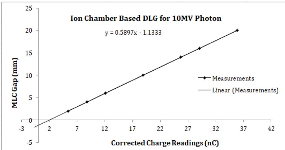 Figure 4: Graph for DLG calculation using solid water phantom with Farmer type ionization chamber for 10MV photon
We fitted a linear function $g(Rg') = aRg' + c$ to points given by gap size $g$ and corrected gap reading $Rg'$. We extrapolated the curve linearly to zero and found the intercept of the fitted function (c). The absolute value of $c$ is the DLG.
### e) Transmission and DLG Measurement from EPID-Based Data
To perform any EPID-based QA-related study, first, it is necessary to calibrate the electronic portal imaging system. We calibrated EPID response to be $100\mathrm{MU} \approx 1\mathrm{CU}$. Using the PDIP technique, the beam exposer was analyzed after exposing the fields on the
EPID. We utilized the iso-center CU value from our exposure field image analysis to estimate the GAP and transmission factor.
The EPID Based Measurement data for MLC transmission and DLG were given in Table 2 using a 3.8 cm solid water phantom (actually 5cm, because there is an integrated build-up of 1.2cm on the EPID) placed on top of the EPID. Measurements were taken using a standard $10 \times 10 \, \text{cm}^2$ field size & 100 MU was delivered for each energy. SSD, SDD and dose rates were identical to the ion chamber-based experimental setup. All of the data reading units are in CU.
Table 2: EPID-based measurements for MLC transmission and DLG using solid water phantom placed on the EPID. All of the data reading units are in CU. $(R_{\mathrm{open}} = \mathrm{Open~Field~CU~Reading~with~Jaw~Setting~10x10cm}^2$ and fully open MLC; $R_{T,A} = \mathrm{Transmission~Reading~for~MLC~Bank - A}$. $R_{T,B} = \mathrm{Transmission~Reading~for~MLC~Bank - B}$ and Gap $=$ MLC Gap with Jaw Setting $10\times 10\mathrm{cm}^2$
<table><tr><td>Energy</td><td>\(R_{Open}\)</td><td>\(R_{T,A}\)</td><td>\(R_{T,B}\)</td><td>Gap 2mm</td><td>Gap 4mm</td><td>Gap 6mm</td><td>Gap 10mm</td><td>Gap 14mm</td><td>Gap 16mm</td><td>Gap 20 mm</td></tr><tr><td>6 MV</td><td>0.972</td><td>0.012</td><td>0.012</td><td>0.035</td><td>0.051</td><td>0.066</td><td>0.098</td><td>0.130</td><td>0.146</td><td>0.178</td></tr><tr><td>10 MV</td><td>1.011</td><td>0.017</td><td>0.016</td><td>0.042</td><td>0.059</td><td>0.075</td><td>0.108</td><td>0.141</td><td>0.158</td><td>0.191</td></tr></table>
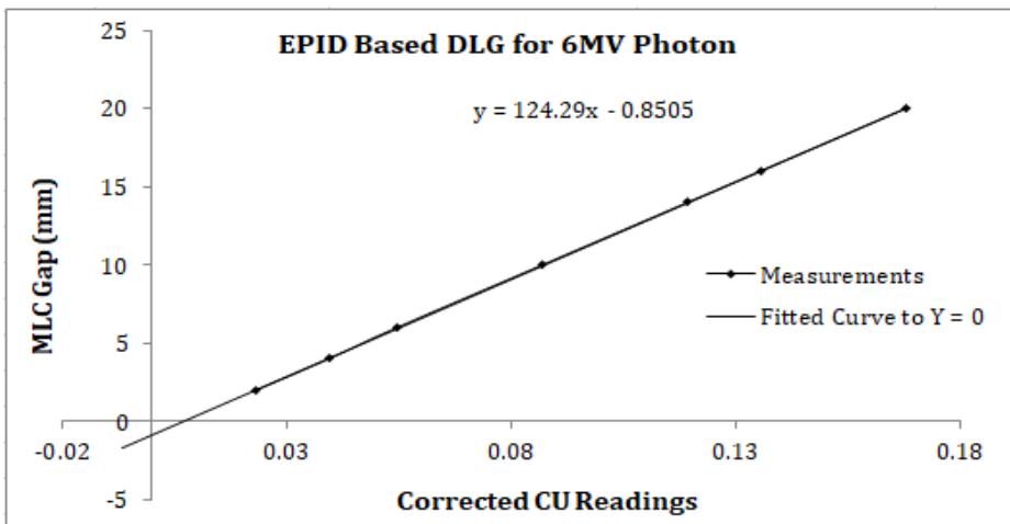
A graphical representation for DLG for 6MV and 10MV photons using solid water phantom with EPID is shown in Figure 5 and Figure 6, respectively. We similarly obtained the DLG to ion chamber-based curve fitting.

Figure 5: Graph for DLG calculation for 6MV photon using solid water phantom with EPID.
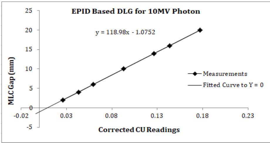 Figure 6: Graph for DLG calculation for 10MV photon using solid water phantom with EPID.
The CU data collection procedure for the open field iso-center is shown in Figure 7 and Figure 8 for 6MV and 10MV photons, respectively. The CU data for the other jaw and MLC settings were extracted similarly from the portal images.
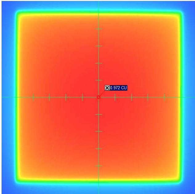
Figure 7: The CU data collection procedure for the open field iso-center for 6MV photon
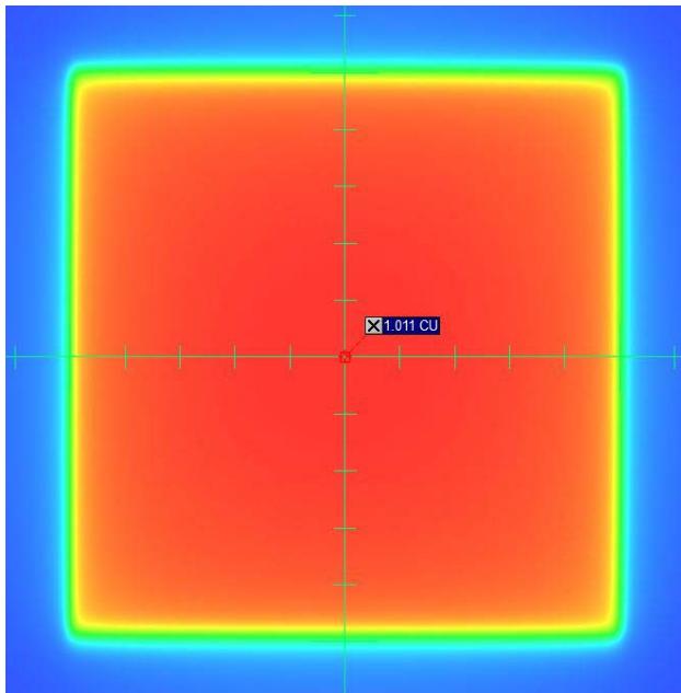 Figure 8: The CU data collection procedure for the open field iso-center for 10MV photon
## III. RESULTS AND DISCUSSION
Transmission radiation through the collimator and DLG are essential functions in modern radiotherapy dose calculation. In modern radiotherapy machines, a multi-leaf collimator (MLC) (mostly 120 leaves) is used, and this device (MLC) is used as an organ-at-risk (OAR) saving tool. According to the radiotherapy goal, a maximum dose should be delivered to the tumour and a minimum dose to OAR [15]. That is why MLC is used in radiotherapy. We can determine the transmission and DLG using a 3D or 1D water phantom, but it takes much time to prepare and set it up. So, it is not easy in busy centers to check transmission and DLG routinely or quarterly in a year. As per Varian machine recommendation, the transmission factor will be less than $2\%$, and DLG will be less than $2\mathrm{mm}$. IMRT or VMAT treatment modalities were extensively developed after the discovery of MLC.
This study investigated the DLG values using the FC65-P ionization chamber with a 5cm thick solid water phantom and VARIAN MV EPID 1200aSi with a similar build-up. Depending on the value of DLG, it may cause errors in dose calculation for a Millennium and High-definition MLC [10]. This parameter accounts for partial transmission through the end of the rounded leaf. It is designed for patients treated with rounded-end MLC to improve dose calculation accuracy in the advanced high-precision radiotherapy technique. Various MLC parameters must be evaluated and verified while incorporating the high-end technique as IMRT/VMAT in Treatment Planning System (TPS) [10].
In comparison with the publication of a multi-institutional survey in Japan entitled "Inter-unit variability of multi-leaf collimator parameters for IMRT and VMAT treatment planning: a multi-institutional survey"[17]. Where they got the value of DLG for the TrueBeam machine is $1.16 \pm 0.22$ mm for 6MV and $1.32 \pm 0.21$ mm for 10 MV Photon Beam. In our measurement, we got the DLG value of $0.98$ mm for 6MV and $1.13$ mm for 10MV photon beams using a Farmer-type IBA FC65-P ionchamber. But using EPID 1200aSi, we got the result $0.85$ mm for 6MV and $1.08$ mm for 10MV photon beams.
Comparing the ionization chamber and EPID-based dosimetry result, we observed that DLG deviation is $0.13 \mathrm{~mm}$ for 6MV and $0.05 \mathrm{~mm}$ for 10MV photon beam. Moreover, transmission factor deviation is $0.23\%$ & $0.06\%$, respectively, for 6MV and 10MV photon beams. In the multi-institutional survey [17], the value of MLC transmission for TrueBeam Machine was $1.50\% \pm 0.05\%$ for 6MV and $1.72\% \pm 0.06\%$ for 10MV photon energy. In our measurement, we got the value of $1.46\%$ for 6MV and $1.69\%$ for 10MV using a Farmer-type IBA FC65-P ionchamber. But using EPID 1200aSi, we got the result $1.23\%$ for 6MV and $1.63\%$ for 10MV photon beam. The published data [17] & our measurement for MLC transmission are in good agreement with ion chamber-based dosimetry, and for EPID-based result, it is a little lower for 6MV photon, that is, maybe for the inhomogeneity characteristics of the photon fluence in low energies and negligible, and for 10MV or higher energy photon, it is almost similar. The results for transmission factor and DLG for both the ionization chamber and EPID-based dosimetry are given in Table 3.
Table 3: The results for transmission factor and DLG for both ionization chamber and EPID-based dosimetry.
<table><tr><td>Energy</td><td>DLG with Ion Chamber (mm)</td><td>DLG with EPID (mm)</td><td>Transmission Factor with Ion Chamber</td><td>Transmission Factor with EPID</td></tr><tr><td>6 MV</td><td>0.98</td><td>0.85</td><td>1.46%</td><td>1.23%</td></tr><tr><td>10 MV</td><td>1.13</td><td>1.08</td><td>1.70%</td><td>1.63%</td></tr></table>
## IV. CONCLUSION
In conclusion, the deviation between phantom and EPID-based DLG and transmission factor will not significantly affect actual radiotherapy patient treatment. So, we can use EPID-based DLG and transmission factor. However, the pre-requisition of EPID will be fully configured before the data acquisition, and the Portal Dose Image Prediction (PDIP) algorithm will be fully configured. Then, we can determine the DLG and transmission factor with just a few shots. We hope that more research on these topics can be conducted in the future with more precise experimental results.
### ACKNOWLEDGEMENTS
We sincerely thank TMSS Medical College & Rafatullah Community Hospital and TMSS Cancer Center for allowing us to use their radiotherapy and dosimetry equipment. A sincere gratitude goes to the chairman and respected teachers of Jagannath University's Physics Department for their encouragement and collaboration on this research. Thanks are also due to Professor Dr Hosne-Ara Begum, Executive Director, TMSS; Dr Md. Matiur Rahman, Deputy Executive Director-2, TMSS; and Professor Dr AKM Ahsan Habib, Project Director & Head of the Radiation Oncology Department, TMSS Cancer Center, for permitting us to use all their facilities.
Compliance with Ethical Standards and Conflict of Interest
No conflict of interest is declared in this research article, and no organization grant for this study project.
Generating HTML Viewer...
References
19 Cites in Article
Justus Adamson,Qiuwen Wu (2012). Independent verification of gantry angle for pre-treatment VMAT QA using EPID.
Todsaporn Fuangrod,Henry Woodruff,Eric Van Uytven,Boyd Mccurdy,Zdenka Kuncic,Daryl O'connor,Peter Greer (2013). A system for EPID‐based real‐time treatment delivery verification during dynamic IMRT treatment.
Karl Otto (2008). Volumetric modulated arc therapy: IMRT in a single gantry arc.
Giorgia Nicolini,Alessandro Clivio,Luca Cozzi,Antonella Fogliata,Eugenio Vanetti (2011). On the impact of dose rate variation upon RapidArc® implementation of volumetric modulated arc therapy.
Eric Klein,Joseph Hanley,John Bayouth,Fang‐fang Yin,William Simon,Sean Dresser,Christopher Serago,Francisco Aguirre,Lijun Ma,Bijan Arjomandy,Chihray Liu,Carlos Sandin,Todd Holmes (2009). Task Group 142 report: Quality assurance of medical acceleratorsa).
Koren Smith,Peter Balter,John Duhon,Gerald White,David Vassy,Robin Miller,Christopher Serago,Lynne Fairobent (2017). AAPM Medical Physics Practice Guideline 8.a.: Linear accelerator performance tests.
Gary Ezzell,James Galvin,Daniel Low,Jatinder Palta,Isaac Rosen,Michael Sharpe,Ping Xia,Ying Xiao,Lei Xing,Cedric Yu (2003). Guidance document on delivery, treatment planning, and clinical implementation of IMRT: Report of the IMRT subcommittee of the AAPM radiation therapy committee.
G Ezzell,J Burmeister,N Dogan,T Losasso,J Mechalakos,D Mihailidis,A Molineu,J Palta,C Ramsey,B Salter,J Shi (2009). IMRT commissioning: multiple institution planning and dosimetry comparisons, a report from AAPM Task Group 119.
E Klein,J Hanley,J Bayouth,F Yin,W Simon,S Dresser,C Serago,F Aguirre,L Ma,B Arjomandy,C Liu (2009). Task Group 142 report: Quality assurance of medical accelerators a.
Ravindra Shende,Ganesh Patel (2017). Validation of Dosimetric Leaf Gap (DLG) prior to its implementation in Treatment Planning System (TPS): TrueBeam™ millennium 120 leaf MLC.
B Mccurdy,K Luchka,S Pistorius (2001). Dosimetric investigation and portal dose image prediction using an amorphous silicon electronic portal imaging device.
Varian Associates Inc Palo Alto Ca (2011). Improved Field Emitter Current Densities and Stability through the Application of a Proprietary Process.
Sandra Vieira,Maarten Dirkx,Kasper Pasma,Ben Heijmen (2002). Fast and accurate leaf verification for dynamic multileaf collimation using an electronic portal imaging device.
K Pasma,M Kroonwijk,J Boer,A Visser,B Heijmen (1998). Accurate portal dose measurement with a fluoroscopic electronic portal imaging device (EPID) for open and wedged beams and dynamic multileaf collimation.
J Chavaudra,A Bridier (2001). Definition of volumes in external radiotherapy: ICRU reports 50 and 62.
Jacob Van Dyk,James Smathers (2005). The Modern Technology of Radiation Oncology: A Compendium for Medical Physicists and Radiation Oncologists.
Masaru Isono,Yuichi Akino,Hirokazu Mizuno,Yoshihiro Tanaka,Norihisa Masai,Toshijiro Yamamoto (2020). Inter-unit variability of multi-leaf collimator parameters for IMRT and VMAT treatment planning: a multi-institutional survey.
Md. Rahman,M Shamsuzzaman,Mmh Bhuiyan,K Khan,Sadiq Malik (2022). Development of spreadsheet for rapid assessment of therapeutic radiation dose delivery with electron and photon beams at various energies.
M Rahman,M Shamsuzzaman (2021). Dosimetric characterization of medical linear accelerator Photon and Electron beams for the treatment accuracy of cancer patients.
No ethics committee approval was required for this article type.
Data Availability
Not applicable for this article.
How to Cite This Article
Md. Motiur Rahman. 2026. \u201cMLC Transmission and Dosimetric Leaf Gap Measurement Using CU Values from Integrated Images of Varian VitalBeam LINAC.\u201d. Global Journal of Medical Research - D: Radiology, Diagnostic GJMR-D Volume 23 (GJMR Volume 23 Issue D1).
Explore published articles in an immersive Augmented Reality environment. Our platform converts research papers into interactive 3D books, allowing readers to view and interact with content using AR and VR compatible devices.
Your published article is automatically converted into a realistic 3D book. Flip through pages and read research papers in a more engaging and interactive format.
Our website is actively being updated, and changes may occur frequently. Please clear your browser cache if needed. For feedback or error reporting, please email [email protected]
Thank you for connecting with us. We will respond to you shortly.