## I. INTRODUCTION
Atoms build up matter and are a source of a great deal of energy. Atomic energy today is used for electricity generation, medical and scientific research, or for exploring of submarine and cosmic worlds. There are over 441 nuclear reactors in operation worldwide. A plant's operating life for a specified service-time period is justified by the required strength margin [1]. Normally, the operating design life of nuclear reactors is 30-40 years [2]. As at April 2022, of all the reactors in operation, 133 had been operated for over 40 years, while the service life of another 164 had exceeded 30 years.
Often the owners of Nuclear Power Plants (NPPs) make decisions to extend the plant life of the power units: these capacities are the source of various benefits for society such as cheap electricity, energy independence, jobs, knowledge and technological development. However, in the operation of Nuclear
Power Plants and particularly the older ones, the level of safety should not be decreased. In Japan, the following analogy is very popular: nuclear safety culture is represented as a person standing on the steps of downward moving escalator. The escalator embodies all load factors of the equipment, the resulting ageing of materials and design obsolescence, human errors, i.e., those contributors to the reducing of nuclear safety. In order to maintain one's position on the escalator, the person has to make constant efforts, while climbing upward requires even greater efforts. Continuous activities are needed to enhance safety culture. In the energy sector, the problem of ensuring the reliability of power equipment performance with each passing year is becoming more and more relevant, as the ageing of equipment significantly outstrips the pace of reconstruction and modernization of the operating capacities. This problem is further complicated by the absence of a scientifically grounded concept of technical diagnostics and lifetime determination, as well as by the inadequacy of traditional non-destructive testing methods.
The opportunities for design life extension of nuclear power plants are demonstrated through analysis, tests and adequate lifetime management for the expected long term operation [3]. Over the past decade, a growing number of countries have been putting the highest priority on the task of lifetime extension of nuclear power units.
This paper reviews the ageing mechanisms of the WWER type of equipment, ageing effects and the corresponding ageing indicators typical for the manifestation of these effects. Identification has been made of the control methods and indicators of function loss of the respective equipment subjected to ageing.
An approach has been proposed for studying the ageing effects on some of the most important nuclear power unit components, i.e., the reactor pressure vessels. Assessments have been performed on the ageing effects of reactor pressure vessels due to load factors such as radiation and thermal impact of the neutron flux, corrosion impact of the primary circuit fluid and hydraulic and thermal impact of the fluid.
# II. OVERVIEW OF NATIONAL APPROACHES TO AGEING MANAGEMENT OF STRUCTURES, SYSTEMS, AND COMPONENTS
The technological development level of individual countries has produced different national approaches to resolve the problems of nuclear energy SSCs ageing management.
### a) Ageing Management Approach of French NPPs
France has been reported to be one of the first countries that started dealing with the problems of ageing equipment at French nuclear power plants. During the 1980s there were three main lines of activity and survey [4]: 1) study of the physical process of degradation with a focus on the radiation embrittlement, 2) the behavior of elements and systems throughout the ageing processes due to thermomechanical and hydraulic impacts; corrosion in the primary and secondary circuits of the power plant, 3) preparation of reliability analyses and development of methods; adopting the understanding that operational experience (OE) serves as a source of data.
At present, France has 56 nuclear reactors in operation, and 14 ones have gone through a final shutting-down for decommissioning [4]. France's main program on the issues of ageing is under the jurisdiction of the French company Électricité de France (EDF) and is implemented in three main steps: 1) SSCs with an impact on the NPP safety, and affected by ageing, get identified, 2) analyses are conducted on the SSCs degradation, taking into account the possibility of maintenance of the facilities, the difficulties regarding the replacement of obsolete equipment and the risk of lacking a waste management technology, 3) detailed reports are written about some components susceptible to ageing (i.e. the RPV, reactor internals, buildings, computer and electrical equipment).
The reactor equipment is the hardest and most complex for replacement. The main degradation mechanism is neutron ageing of the material, yet ageing by this mechanism is "well managed" (according to the French power engineers) except under conditions of thermal shock. This event could cause brittle fracture of the reactor pressure vessel material. But such a scenario is part of the design of the French nuclear power plants, using special steels with chemical elements, such as copper and phosphorus that are naturally resistant to neutron embrittlement. These elements enable lower temperature values of elastic-to-plastic transition in the metal. Depending on how low these reference temperature values are maintained, it is possible to determine how ageing will be affected and to predict the performance value at the end of the design life of the reactor (i.e., after 40 years).
### b) Ageing Management Approach of the Hungarian NPP
In Hungary, there are four WWER type of reactors (Paks Nuclear Power Station). The plant lifetime characteristics have been evaluated. The plant life has been extended by 20 years. A characteristic feature of the Hungarian approach is that a dedicated Hungarian regulatory basis has been developed, i.e., the Hungarian Guideline 4.14 [5], to deal with ageing issues. The ageing management programs include: 1) identification of degradation mechanisms and the affected component (SSC), 2) ageing mitigation and prevention measures, 3) specifying monitoring parameters, 4) detection of ageing effects, 5) monitoring and trending, 6) acceptance criteria of the evaluation results, 7) corrective actions, 8) feedback, effectiveness and improvements.
### c) Ageing Management Approach of the Spanish NPPs
Spain has seven nuclear reactors. The Spanish approach regards the SSCs ageing management as a process that requires periodic re-evaluation and upgrade. A major source for streamlining the process is the feedback from operating experience. Many of the changes to the Spanish NPP ageing management programs concern the SSCs maintenance activities, e.g.:
- Preparation and verification of a new guide book on SSC maintenance activities, with a focus on the conditions of accessibility to the equipment.
- Training practice in duty tours and walkdowns.
- Improving the identification of structural components.
The mechanism of flow accelerated corrosion (FAC) is turning into a challenge to the ageing management process, as a large part of the carbon steel equipment necessitates replacement. Another growing issue is that of inspection and control of some concealed underground (buried) pipelines, due to difficulties in using standard tools. Studies are focused on search of new technological solutions.
### d) Ageing Management Approach of the NPPs in the Czech Republic
The Czech Republic operates six nuclear power reactors. The Czech methods and criteria for identifying SSCs within the scope of ageing management require:
- Summarizing the data on equipment ageing.
- Conducting of assessments and documenting potential mechanisms for properties degradation that could affect the safety functions.
- Continuous activities to expand the current understanding of all the dominant mechanisms of ageing.
- Availability and adequacy of the data needed for ageing assessment, including design basis data, and maintenance and repair data.
- Implementing effectiveness evaluations of the maintenance and repair programs in terms of ageing.
- Identifying criteria and indicators for safe operation over the long-term operation (i.e., operation beyond the design life term).
- Conducting assessments of the physical condition of SSCs, including the current safety indicators and conditions that may limit the operation lifetime.
The ageing management of SSCs important to safety requires that degradation be controlled in accordance with specified criteria. Effective control of the ageing degradation is needed through systematic assessments of maintenance and repairs, so that this may result in minimization of ageing trends, and preservation of the integrity and functional capabilities of the SSCs.
### e) Ageing Management Approach of the NPPs in Canada
In Canada there are 19 reactors in operation of the deuterium-uranium unit type (CANDU). In the equipment screening process, two categories of components have been identified: critical components and less critical ones [6]. The following actions are taken in the course of the ageing management process: 1) assessment of the plant lifetime characteristics of critical non replaceable equipment (mainly passive equipment), 2) systematic assessment of the maintenance actions for critical SSCs through analyses of the operating states (modes) in which failures occur, 3) condition assessments for less critical equipment components, and for the remaining SSCs.
The types of critical non replaceable equipment subject to ageing management include: fuel channels, steam generators, reactor units, reactor building and civil buildings, pipelines, turbine generator, pumps and heat exchangers, electric motors, breakers and cabling systems, pumps and buildings.
The less critical components and equipment have been allocated in groups per some typical characteristic, i.e., commodity groups (pumps, tools). Each group undergoes specific operability analyses. The ageing management methodology includes:1) reviewing the entire operational history of the component, its design and fabrication in terms of ageing characteristic features, 2) diagnosing the ageing stress factors and the mechanism of properties degradation under all operating modes. Evaluating the component maintenance in terms of ageing management effectiveness.
### f) Ageing Management Approach of the NPPs in the USA
The USA have 96 reactors. The components get assigned to categories based on their significance for the reliable and cost-efficient nuclear power plant operation. To this effect the following criteria are used: 1) ageing effect (potential one), 2) affecting the component's intrinsic functions, 3) identifying the corresponding ageing management activities to ensure that the expected functions of the components are supported.
The SSCs assessment is made on the grounds of NEI 95-10 guideline [7] and is in fact an integrated assessment of the nuclear power plant and a review of the time-limited ageing analyses for SSCs covered by the license. This integrated assessment of NPP consists of identification of the components' materials and their interactions with the environment, the applicable ageing effects that may impact loss of the anticipated functions, as well as a lifetime management program needed to support these functions.
The time-limited ageing analyses contain qualification for the environmental impacts, fatigue toughness and neutron embrittlement resistance analyses.
An element of key importance for the continuous improvement of ageing management at US nuclear power plants is the use of OE feedback together with incorporation of the lessons learned in the ageing management programs.
### g) Ageing Management Approach of the NPPs in the India
The Nuclear Power Corporation of India Ltd (NPCIL) conducts the lifetime extension process of the Indian NPPs in accordance with its own NPCIL instruction HQI-7005, based on the IAEA Safety Specific Guide SSG-30 [8]. The main points of this instruction include, as follows: 1) SSCs screening and ranking as per level of importance of the NPP safety, 2) ageing methodology that comprises degradation effect and is based on the degradation mechanism, 3) evaluation of the SSC maintenance, 4) inspection of SSCs and degradation prevention techniques (maintenance, rehabilitation or replacement).
In terms of material properties degradation, the equipment has been allocated in four categories:
- Category 1: Major SSCs, of critical importance and limited lifetime.
- Category 2: Critical SSCs.
- Category 3: Important SSCs.
- Category 4: Other SSCs.
The regulatory system of India does not specify a limit to the time period for operation of an NPP. The power plants can continue operation as long as they meet the regulatory requirements and satisfy the safety measures.
### h) Ageing Management Approach of the NPPs in China
The first Chinese NPP, Qinshan-1, entered in commercial operation in 1991. Since then, 15 WWER nuclear power units have been constructed and commissioned as well as PWR H CANDU ones.
Safety factors have been checked during each periodic safety review: 1) documented procedure and criteria for identification of SSCs impacted by ageing, 2) list of SSCs incorporated in ageing management programs, and records that this provides data in support of the ageing methodology, 3) evaluation and documenting of each potential degradation mechanism that may affect the safety functions of SSCs, 4) broadening of the understanding of the dominant ageing mechanisms, 5) applicability of data for degradation assessment including design data, historical operation and maintenance data, 6) effectiveness of the operation and maintenance programs in terms of ageing management of replaceable components, 7) availability of programs for timely detection and prevention of ageing, 8) acceptance criteria and required safety limits for SSCs, 9) informing about the physical condition of SSCs, including current safety limits and future events (any events) that may put limitations to the operating lifetime of the facility.
### i) Ageing Management Approach of the NPPs in the Republic of Korea
The selected criteria for components affected by ageing and subject to lifetime extension involve a number of standards and normative documents including regulations for periodic safety reviews (PSR), US regulatory documents [7], and definitions of quality class implemented in Korea:
- Safety related components (Quality Class "Q").
- Non-safety related components the failure of which may affect safety functions (Quality Class "A").
- Other components.
The current physical condition and level of degradation of the SSCs are evaluated by means of referring to the design and manufacturing data, taking into consideration the data from testing, operation and maintenance, in accordance with the applicable standards.
The ageing management review produces analyses of whether the selected properties degradation mechanisms (ageing mechanisms) can affect SSC. These mechanisms are evaluated as follows: 1) It is determined if the ageing mechanism found for a given item forms part of the 17 mechanisms as specified in ASME Boiler and Pressure Vessel Code [9], 2) each ageing mechanism is identified, 3) the frequency and conditions of the occurrence of each ageing mechanism get identified, 4) determination is made of the type of mechanism(s) applicable to the examined component, 5) consideration is given to the availability and applicability of any operational experience.
### j) IAEA Documents of the Ageing of NPP Equipment
The document IGALL Ageing Management of Nuclear Power Plants [10] provides guidelines on the potential content of an integrated ageing management program, as well as on the assessment of the ageing management program effectiveness. The NPP self-assessment of the ageing management measures shall include, as follows: 1) implementation of all in-plant measures for safety assessment, such as PSA periodic conduct, 2) conduct of external oversight - on behalf of the regulatory authority, as well as on international level (SALTO review missions of the IAEA), 3) comparing, on a periodic basis, the ageing management activities against those implemented on other NPPs (benchmarking process). It is assumed that the ageing mechanisms of the same type of equipment are the same on the different NPPs. However, an ageing effect may be manifested on one NPP, and not manifested on another one, or occur at a later stage of the operation of the particular equipment. In view of this, benchmarking against the practices of other NPPs assists in the prevention of ageing.
IGALL Ageing Management of Nuclear Power Plants [10] contains tables covering all types of materials on an NPP, all types of components, intrinsic degradation mechanisms and ageing effects.
The unified procedure Nulife, or Verlife [11] is a technical document (TechDoc) of the IAEA and it provides a methodology for: 1) assessment of the residual lifetime and integrity of components and piping of NPPs with WWER type of reactors in the course of their operation and in terms of defects caused by ductile and non-ductile fracture, fatigue and mechanical corrosion damages as a result of their operation, 2) assessment of the indications found during in-service inspection (ISI) of components and pipes, 3) preparation for reports from the periodic safety review during an NPP operation, in the part regarding the residual lifetime of equipment, 4) management of modifications of NPP equipment residual life.
## III. AGEING EFFECTS STUDY METHODOLOGY
Technical disciplines have been emerging based on requirements for failure and defect prevention and ageing management of mechanical and electrical system for plant life extension [4].
Failures and defects of equipment and pipelines occur when a limit condition has been reached. Limit conditions are attained in the following circumstances: 1) upon reaching of unacceptable residual changes of form due to plastic deformations, corrosion, mechanical or erosion wear, 2) upon the emergence and growth of discontinuities, 3) when the service life characteristics have reached their ultimate limit values, for example the acceptable number of load cycles.
The approach to ageing effects study shall satisfy the following main requirements:
- Protect the equipment from ageing;
- Monitor the consequences of ageing;
- Compensate the consequences of ageing;
- Improve the equipment control programs in the light of new knowledge accumulated including the programs for surveillance specimens' analysis.
- Effectiveness assessment of the testing methods and the programs.
### a) Preparations: Data Acquisition
A thorough and extensive data acquisition is effected through review and analysis of the design and manufacturing documentation of each component, resulting in systematization of: 1) datasheet and design data about the facilities, 2) design changes and modernizations undertaken, 3) provisions of the normative documents, 4) operational history and testing data, 5) maintenance documentation, 6) strength analyses data, 7) data about compatibility with other components and systems, 8) results from in situ inspections (control), 9) data on the implemented operating modes, hours, number of load cycles, hydraulic tests, etc.
### b) Strength Analyses
The performance of strength analyses is a mandatory part of the ageing management process [12]. All the relevant information on structural materials, geometry and design characteristics, the rest of the data from the design documentation and the components' datasheets serve as input data for the strength analyses. The cyclic fatigue effects, caused by the operational fluid need to be considered in the calculations. The current operational modes, all data about defects and non-conformances regarding the design parameters also need to be taken into account in the strength analyses. The average loads spectrum over the past 10 years of the NPP operation shall be used as a model for the future annual load. The calculations may also consider the rest of the loads. Based on the results of the strength analyses, it has been found that in the most stressed areas the metal can potentially be exposed to the highest level of ageing resulting in degradation of physical-mechanical properties, due to ageing factors such as thermal deformation and low-cycle fatigue. Occurrence of a crack may be expected in the zones of highest stress (load). Therefore, in those areas where the strength analyses indicate a potential for failure, special emphasis is placed on testing and non-destructive testing, for example, in the places of welded joints.
### c) Selection of Sample Components
Ageing affects all the SSCs of a nuclear power plant. Naturally, it is not possible to subject to systematic survey for ageing effects all their thousands of components. Screening of the components due for a more extensive analysis of ageing is affected on the grounds of various factors, e.g.:
- The time in which they have been in operation.
- Number of the strength cycles.
- Conditions of operation, especially those conditions that are most relevant to the crack formation.
- Which components can be renovated through welding.
Components are allocated in groups on the basis of similarity signs. These signs may differ, but most frequently components are grouped by functional identity (e.g., the steam generators group). Other type of grouping may be founded on the results from testing, e.g., a group of components with defects that exceed certain size.
From the group, a component is selected because it is in the most unfavorable position in terms of ageing: for example, it has the worst physical condition, or it is the hardest to accessible for control purposes, or it has been subjected for the longest time to the aggressive influence of environment. From the entire group of components, one sample component can be selected to be used for an in-depth analysis of the ageing trend. After conducting these analyses, the results can be applied to the other components in the group.
After a sample component has been selected and its condition analyzed, it is assessed whether there is a need to expand the scope of inspections and monitoring, carried out up to that point, so as to cover the entire group of components. In the event of obtaining satisfactory results for a typical component, it is not necessary to extend the scope of the inspection. While if the results of the control (testing) are not satisfactory according to one or more criteria applied, then an increase in the scope of the ageing control may be recommended.
For each component, data is collected. The data collection for each component is systematically supplemented with results from regular non-destructive and other testing, component maintenance data, and information on high stress potential areas.
### d) Regular and Extraordinary (Additional) Studies of Characteristics of the Mechanical Equipment
The regular studies due for each component have been described in the technical specifications for the operation of the nuclear power unit.
Additional measurements include, as follows: 1) precise measurement of the mechanical properties by means of a kinetic penetration method (kinetic hardness method), 2) ultrasonic testing of the welds integrity by means of the phased array technique, 3) on-line measurement of the decreasing wall thickness of metal facilities using combined electromagnetic-acoustic methods for selected carbon steels of pipelines subject to erosion-corrosion. This method enables 3-D scanning of the object, in order to detect cracks and wear, and permits the identifying and localization of the area of maximum metal wear.
### e) Evaluation of the Adequacy of Ageing Management Activities
Ageing management activities include testing, monitoring, control, feedback and operational experience implementation, etc. These measures are apparently sufficient if the component is in good condition. On some NPPs, it has been established that for some components, for which control/monitoring is not required as per the unit's technical specifications, no tests have been conducted at all during the years of operation. This fact points to serious gaps in the maintenance and repair system, incompatible with the management of ageing processes:
1) equipment has been found not covered by the maintenance and repair measures (polar crane and refueling machine, RPV supports), 2) equipment that is on the borderline between two systems and has not been included in the scope of the maintenance and repair programs, 3) no regular periodic measurements have been made of the mechanical properties (strength, hardness) in areas with potential for failure.
In such cases, additional examinations of the mechanical properties of the metal are prescribed and carried out, in addition to the regular surveys, for example, a hardness testing is prescribed. The adequacy of the maintenance and repair measures is evaluated in terms of the activities described above.
### f) Identifying the Degradation Mechanisms of the Mechanical Properties
The mechanisms of mechanical properties degradation are identified for each commodity group [10,13]. The ageing effects attributable to each mechanism are determined. Determination is also made of the ageing indicators through which the effects are manifested. The testing and diagnostic methods are defined by means of which the ageing indicators are monitored. These methods get described in ageing management programs for each commodity group.
### g) Evaluation of the Effectiveness of Ageing Management Measures
The evaluation of the effectiveness of ageing management measures shall take place on a regular basis. The information items listed below serve as input data for evaluations [14, 15]
- The component condition, including the defects manifested in the facilities.
- The degradation mechanisms, i.e., those already defined and the potential ones.
- Whether the ageing effects are typical (characteristic) of these mechanisms.
- Whether the ageing indicators have been correctly identified.
- Whether the testing methods (control and monitoring) are sufficiently sensitive to capture the changes in the ageing indicators.
- Whether the periodicity of testing is adequate. If discontinuities have been found, the interval between inspections has to be shortened.
- Whether the scope of the inspected equipment is adequate.
- Let's take a closer view of the process of ageing of materials.
## IV. AGEING OF MATERIALS AND DEGRADATION OF MECHANICAL PROPERTIES
Ageing of materials stands for the change in their mechanical, physical and chemical properties, due to thermodynamic imbalance of the initial condition, and gradually bringing the structure to equilibrium in the presence of sufficient diffusive mobility of the atoms. Investigations of the ageing processes during NPP operation comprises activities such as
- Development of methodologies and instruments to diagnose the parameters of NPP in-service equipment.
- Assessment of the ageing effects on the operability of equipment in view of making corrections to the scope and periodicity of outages, maintenance, tests and inspections.
- Development of methodologies for express analysis of failures, damages and defects of components of equipment, and introducing those methodologies in the operational practice.
- Establishing an NPP information system (a database of knowledge and expert system).
### a) Corrosion
Corrosion is the process of metal failure as a result of chemical or electrochemical interactions of metal with the surrounding environment [16]. The cause of corrosion is the thermo-dynamic instability of the system, composed of the metal and components of the environment. The capability of metals and alloys to resist corrosion impact of the environment is contingent on the rate of corrosion under the given conditions. The following serve as quantitative indicators of the rate of corrosion
- The time until the occurrence of corrosion outbreaks.
- The number of corrosion outbreaks for a given time period.
- The metal thickness decreases per time unit.
- The change of metal mass per surface unit and time unit.
- The change of any indicator of mechanical properties such as strength, plasticity, electrical resistance, etc.
### b) Erosion
Erosion of the walls of equipment is caused by particles of various origin such as particles of metal corrosion products, sand, silicates, water drops, etc. The erosion process evolves through brittle or plastic fracture depending on the temperature.
1. Under normal temperature conditions in the plastic metals, erosion dissociation of metal occurs as results of plastic deformation on the surface. With brittle materials, erosion takes place through surface degradation in the form of cracking.
2. High temperature erosion is associated with the release of composite material - metal alloy and brittle surface oxide. The oxide layer on the metal surface may modify the process mechanism depending on the layer thickness. If the oxide layer is thin, the prevalent mechanism is associated with metal creep (elastic-plastic area). Upon the oxide layer reaching a critical thickness, the dominant mechanism is that of brittle erosion fracture.
The temperature and the characteristics of the force impact of the particles are the erosion determining parameters. The speed of oxide formation is dependent on temperature and, therefore, the same applies to the oxide layer thickness within a given timeframe. The force effect of particles is characterized by the time intervals of particles impacting on a specified point on the metal surface.
### c) Ageing Effects Due to Corrosion-Erosion Processes
The corrosion-erosion processes that are typical for NPPs, type WWER consist in corrosion degradation of materials, followed by erosion wear under the impact of the fluid flow rate. Factors affecting the process include: 1) fluid composition, 2) velocity and temperature, 3) the component material and geometry, 4) the active stresses, 5) the periodicity of surface moisturizing/drying. Localized corrosion affects steam generators and reactor sealing surfaces, pressurizers and emergency core cooling system (ECCS). Intergranular corrosion can be observed on reactor, steam generators, corrosion fatigue - on steam generators and pressurizers. Stress corrosion affects reactors, steam generators, pipelines of the pressurizer systems and ECCS piping.
Regarding the bends in the pipeline system: Stresses will lead to a considerable change in the metal electrode potential. Tensile stresses (tensions) shift the electrode potential to the negative side, while the compressive stresses shift it to the positive side. The stretched sections act as anodes with regard to the rest of the metal and degrade (dissolve) most intensively.
The corrosion-erosion processes decrease pipeline wall thickness. There is increased probability of pipeline rupture and leaks of coolant. The change in the geometric dimensions of the pipeline walls leads to a change of the internal stresses. The system's failure rate increases on account of material degradation. The corrosion-erosion processes are the cause for loss of tightness of the pipeline systems. Thus, the normal operating conditions are compromised. Abnormal operation of the heat exchangers occurs as a result of the rupture of heat exchanging tubes. The general radioactivity levels increase due to activation of the corrosion products.
One of the ageing indicators is the pipeline wall thickness and it is measured periodically. The corrosion rate is inspected on a periodic basis. Tests are performed to identify presence of number, type, location and growth of surface defects, pits, and blow-holes in metal, and percentage of wear of the wall thickness of heat exchanging tubes. Conduct regular ultrasonic thickness measurement testing of walls and bends. The area surround-ding the weld joints is monitored.
Monitoring is performed of the water chemistry of the fluid inside the pipeline. The water chemistry regime is analyzed and maintained. The radioactivity indicators are measured. Corrosion evaluation for presence of sludges or deposits is to be performed of the critical areas. In-service inspection of metal is performed (visual, penetrant, eddy-current and mechanical testing). To prevent intergranular corrosion, visual inspection, surveillance specimens testing, penetrant, ultrasonic and hydraulic testing are undertaken.
### d) Neutron Embrittlement
The operating conditions of the reactor pressure vessels metal are characterized by intensive neutron flux under high temperature and pressure conditions [17]. Being particles of small mass and great energy, neutrons easily penetrate the crystal lattice of the reactor pressure vessel. There are two major mechanisms of the interaction between neutrons and the particles of materials:
1. The collision between neutrons and the lattice atoms causes dislocations within the crystal lattice; neutrons may either transfer their energy to atoms through elastic impacts, or serve as the source of charged particles formation. Such processes will impair the correct position of atoms within the metal crystal grid and this will lead to defects formation. In
case of sufficiently high neutron energy, the atom initially displaced from its balanced position may be followed by a cascade of displaced atoms.
2. Radiation impact largely facilitates diffusion of the ingredient's atoms, which is another important cause for alloy embrittlement. Moreover, as results of vacancies merging in those diffusion processes, additional pores may form in the metal, which can result in noticeable changes in the shape of the structure.
The density of radiation defects depends on the type of radiation, its parameters and the nuclear-physical characteristics of the material. The spot defects that occur – vacancies, internodal atoms, embedded atoms at sufficiently high temperature can recombine, migrate to body or surface directed leakages (dislocations, grain boundaries) form radiation stacking faults in the shape of pores and dislocation nodes. The irradiation of metal with fast neutrons results in microscopic areas of structural damages, and with high concentration of spot defects. Due to irradiation, the creep (yield) stress limit of steel may grow up to twice fold, while the strength limit increases to a lesser degree – the two limits come closer and metals harden while also losing plasticity. Current knowledge of radiation degradation assumes that the occurring defects may lead to material hardening either directly via interaction with the dislocations, or indirectly - through the changing kinetics of metallurgical reactions leading to phase drop. These effects harden the material and are dependent on neutron fluence density. The main effect of radiation degradation of metals consists in the highly limited number of active slip planes, and increased number of dislocations moving across the slip planes. This highly localized movement affects the process of local degradation in the peak of the crack. Determining the transition from elastic to brittle state or the evaluation of the shift of the brittleness critical temperature $\Delta T_{F}$ due to the neutron fluence $F$, may be performed through experimental testing of surveillance specimens, or it can be assessed numerically through the neutron fluence $F$. Neutron embrittlement is expressed in radiation brittleness temperature $\Delta T_{K}$ shifting in the direction of higher temperature values. Numerical assessment of neutron embrittlement of the reactor vessel metal is carried out using norms and standards of the country manufacturing the reactor equipment.
Due to the neutron diffusion, near the peak of the crack a circle section of embrittled metal forms, as is shown on "Figure 1". The embrittling action of metal neutrons is dependent on their density of distribution [17].
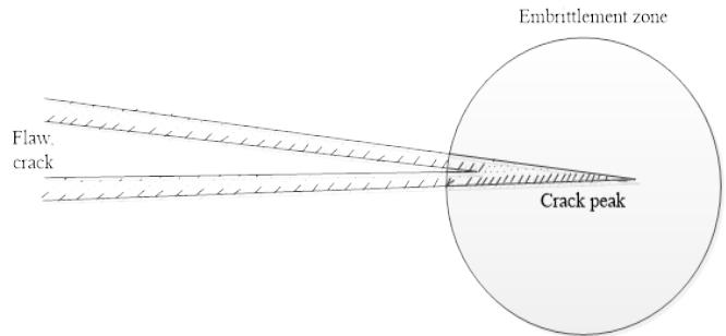 Figure 1: Material Embrittlement Around the Crack Peak
### e) Effects of the Chemical Composition of Steels on the Embrittlement
The steels used for NPP's equipment are of ferrite-perlite type. The elevated levels of the elements nickel Ni and manganese Mg in reactor steel grades enhance embrittlement due to the formation of nickel-manganese-silicon Ni-Mn-Si clusters (dislocation nodes). "Figure 2" shows photos of microscope examination of samples with various weigh percentage of Ni, subjected to neutron fluence irradiation [18].
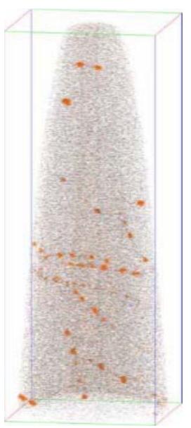
0.02%Ni
0.82%Ni
1.59%Ni Figure 2: Formation of Dislocations in Samples of Varying Weight Percentage of Ni (0.22 Cu - xNi - 1.6 Mn) at Temperature 290-320 °C
During irradiation the structure of materials containing copper Cu changes and Cu-enriched clusters form. The Cu-nucleus stays in the middle of the formation, while the elements nickel Ni, manganese Mn, silicon Si accumulate in the outlying sections.
These formations disrupt the correct structure of the crystal lattice. Under the impact of the operating temperature of $320^{\circ}\mathrm{C}$, higher phosphorus content will result in thermal brittleness of metal following a mechanism based on the phosphorus segregation at the interphase boundaries and the grain boundaries. Radiation embrittlement is determined by the formation of dislocation nodes. The occurrence of these defects results in: 1) facilitating the emergence of cracks and development of micro crack on account of the active stresses, 2) additional micro stresses begin to act in the grain bodies, 3) increased probability of formation of dislocation aggregates at the barriers where micro cracks form. The neutron embrittlement mechanism is associated with the segregation of phosphorus at the inter-phase boundaries of the carbide matrix and at the grain boundaries, as a result of which their strength diminishes.
#### Thermal Ageing
In NPP facilities in operation undergo the impact of high temperature values. These working medium factors may cause thermal ageing of the base metal and weld metal in terms of alteration of their mechanical characteristics [19]. Thermal ageing is associated with displacement of atoms in the lattice of the crystalline structure; it is mainly dependent on temperature and the time period over which the metal has been exposed to its effects.
Regarding the reactor vessel materials, neutron fluence causes both thermal ageing and radiation ageing of the metal. The thermal ageing mechanism has been determined by the carbide's formation process. In the course of thermal treatment, carbon bonds in stable carbides do not change under the operating temperatures over the whole service life of the materials. Upon carbides emergence and as their amount grows, the material hardens and, as a result of this, it also becomes brittle.
The thermal ageing affects the reactor pressure vessel, barrel, core baffle, and reactor guard-tube bank. Factors affecting the process include: 1) fluence values and direction, 2) the chemical composition of materials. The elevated content of nickel Ni and manganese Mn enhance thermal embrittlement due to the formation of clusters in the radiation environment, while the content of silicon Si reduced embrittlement.
The loss of functions due to the thermal ageing is observed. There is a growing probability of brittle fracture of materials especially for the welded joints of the reactor vessel located opposite the reactor core. As a consequence of radiation swelling of metal there is growing probability of shape changing of components (core barrel); this will lead to altered load bearing capacity of the structure.
Both neutron and thermal ageing can be presented with the embrittlement function $\Delta T_{K}(F,t)$ - the shift of the critical brittleness temperature, which is depended from the values of neutron fluence $F$ and time t [9,10]. The value of the shift $\Delta T_{K}(F,t)$ needs to be within the acceptable design limits [8]. The parameters monitored are presence of number, type, location and development of surface and internal discontinuities. The neutron flux values following each fuel cycle are recorded. In-service inspection of metal is performed (visual, penetrant, ultrasonic, eddy-current and mechanical testing). The mechanical characteristics are studied periodically, including the variation of the shift $\Delta T_{K}(F,t)$ of surveillance specimens from the reactor vessels. Thermal hydraulic analyses are conducted, as well strength analyses. Low-leak schemes of core refueling are used. Visual and measurements inspection of the core barrel are performed. The barrel geometry dimensions are monitored.
### g) Material Fatigue
Engineering structures are subjected to pulsating (cyclic) loads [20, 21]. Under the in-fluence of cyclic loading, it is difficult to notice any progressing changes in the structure of the material. Destruction happens suddenly, without any noticeable signs of imminent occurrence. Moreover, in times of "relaxation" when stress stops acting, defects do not disappear – they accumulate and are irreversible. Fatigue can be described as a process of gradual degradation, composed of sub elements, such as: 1) the process of crack emergence, 2) crack growing to a size when its further progress is rapid and unstable. It is assumed that a crack originates as a result of the movement of dislocations, which generates thin sliding planes on the surface of the crystal lattice.
### h) Ageing Effects Due to Fatigue
Cyclic fatigue affects all the main equipment pieces of the primary circuit (reactor, steam generator, main circulation pipeline, main coolant pump). Low cycle fatigue affects the secondary circuit equipment (turbine, demineralizers, separators).
Factors affecting the process include: Number N of the work cycles, amplitude of the deviation of the stress.
Loss of function of the equipment due to fatigue is observed. There is increased probability of fatigue degradation of materials. Subsequent change in the load-bearing capability of structures is expected.
The number of load cycles is monitored for the different operating modes. Monitoring is performed of the following parameters: presence of number, type, location and development of surface, below surface and internal discontinuities. The fatigue accumulation factor is periodically calculated. The load cycles are registered and monitored for the different design operating modes. A register is maintained of the number of loading cycles. Surveillance specimens are tested. In-service inspection of metal is performed (visual, penetrant, ultrasonic, eddy current testing) [22, 23]. Hydraulic testing is implemented. Fatigue analyses are performed.
### i) Wear
Multiple studies have demonstrated that the process of gradual loss of functionality of components in operation can be subdivided in three stages: 1) stage of alignment, 2) normal operation stage, 3) wear, caused by facilities' normal operation.
Throughout the stage of alignment mutual changes occur in the macro- and micro-geometry of the working faces, and products of wear and oxidation are formed. The working faces wear rather intensively during this stage. Gradually, wear weakens and stabilizes to a stage of normal operation wear. Once the energy limit has been exceeded, the wear value progressively increases, the components functioning deteriorates and the need of repair arises. The following factors determine the level of wear in friction: 1) physical, chemical and mechanical properties of the surfaces subjected to friction,2) combination of materials for the working surfaces, 3) interactions of the working surfaces with the environment, 4) clean processing of the friction surfaces, 5) type of friction (dry, boundary, semi liquid, liquid), 6) values of the normal pressure and the velocity of working surfaces one against the other.
Of the large number of wear types on the working surfaces of machine parts, major importance is attached to abrasive wear in the presence of grease, because the wear products that invariably arise from the machine components friction are oxidized and turn into a sort of abrasive materials and it is rather complicated to clear lubricants from the component surface. Friction wear is one of the major contributors to the gradual loss of operability of mechanical elements. Therefore, the consideration of factors affecting the level of wear of machine parts during design and operation of mechanical systems is one of the main tasks for ensuring the reliability of the working mechanical elements in Nuclear Power Plant.
### j) Ageing Effects Due to Wear
Wear affects hydraulic snubbers, sealing faces, fixing elements, internal parts of cylindrical vessels and pipelines. A photo of wear is presented on "Figure 3".
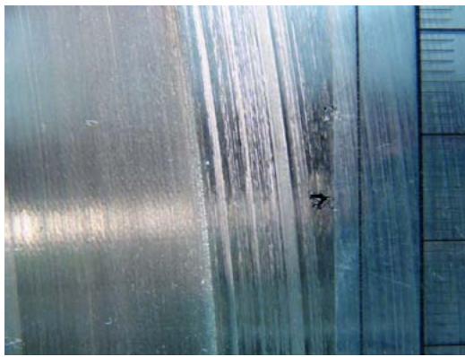 Figure 3: A Photo of Wear on Rotating Part, it Can Be Seen a Defect in Metal
Erosive wear is an issue for pipeline operation in the turbine hall. Defects of erosive nature occur at pipeline bends, and also in pipeline sections downstream of throttle and control valves. The cause for such defects is the presence of two-phase medium in the pipes and development of cavitation processes.
Plastic deformation affects steam generators, pressurizers, pipelines, of the pressurizers' system, main circulation pipelines and ECCS.
Loss of function of the equipment due to wear can be observed in a case of hydraulic snubbers' degradation. The snubbers are incapable to performing its protective functions in case of strong vibrations, or an abrupt displacement of equipment caused by seismic loads. Regarding pins (their cylindrical part) and pin sockets - their fixing functions is impaired and it is probable that fixing will not be tight enough.
Erosion-corrosion wear processes decrease pipeline wall thickness. There is increased probability of pipeline rupture and leaks of coolant. The load-bearing capacity of the affected structures is changed.
Visual testing is performed to identify presence of number, type, location and development of any surface discontinuities. The pipeline wall thickness is measured periodically.
## V. AGEING EFFECTS OF REACTOR PRESSURE VESSELS
This part of the paper reviews ageing effects of reactor pressure vessels (RPVs).
The underlying factors for selecting these items to be subjected to ageing assessment are as follows:
1) The operating life is greater than 30 years in a row.
2) Large number of the strength cycles.
3) Operating environment conditions: fluid pressure of $17.8 \mathrm{MPa}$; fluid temperature $20 \div 330^{\circ} \mathrm{C}$; the fluid flows at high speed.
The subject of assessment was the reactor pressure vessel metal, and the RPVs type WWER 1000 -
B 320, thermal power of $3000 \mathrm{MW}$. Two power units were the subject of survey: unit "a" and unit "b". The survey period covers 30 years.
The RPV metal is subject to the following degradation mechanisms due to the operating environment factors such as neutron embrittlement, thermal ageing, embrittlement due to the presence of discontinuities, fatigue, and erosion-corrosion wear [13].
### a) Study of the RPV metal ageing caused by neutron embrittlement and thermal ageing mechanisms
Subject of study are the welded joints metals of the RPVs of two type WWER reactors (provisionally referred to as "a" and "b"). The reasons justifying the choice of the specific areas for the study is that areas with degradation potential are identified in these RPV points. The welded areas have different metal structure (area of base metal, thermal impact area, and welded metal area) and the structural non uniformity is one of the main causes for the occurrence of discontinuities. The tensions active in the metal and resulting from the operating conditions are not the same for the bimetallic areas, which leads to the growth of discontinuities. The welded joints located opposite the reactor core are subject to the embrittlement action of high neutron fluence. Discontinuities were found at the places of welding; their evolution has been traced over the years of reactor operation.
The embrittlement process depends not only on the chemical composition of the alloys, but also on the values of neutron fluence, operating temperature and running hours, which can be expressed as shown below [11, 19]:
$$
T_{K} = T_{K_{0}} + \Delta T_{K}(F,t)
$$
The value added to the temperature $\Delta T_{K}(F,t)$ shift has two components: one of the components is due to the neutron fluence $\Delta T_{K}(F)$, and the other one is due to the thermal embrittlement $\Delta T_{K}(t)$.
$$
\Delta T _ {K} (F, t) = \Delta T _ {K} (F) + \Delta T _ {K} (t) + \omega \tag {2}
$$
- $T_{K_0}$ is the metal initial critical temperature that corresponds to non-irradiated condition;
- $T_{K}$ is the metal critical temperature following a period of irradiation;
- $\Delta T_{K}(t)$ is the metal critical temperature shift, resulting from thermal ageing;
- t running hours of the reactor metal;
- $\Delta T_{K}(F)$ the critical temperature shift, resulting from neutron irradiation due to the neutron fluence $F$;
- $F$ is the neutron fluence of neutrons whose energy exceeds 0.5 MeV, hitting the pressure vessel;
- $F_{0} = (10^{22}\mathrm{n}) / \mathrm{m}^{2}$ is a standardised factor;
- $A_{F}$ is the radiation-induced embrittlement factor;
- $\omega$ -double standard deviation of $\Delta T_{K}(t)$;
- $\Delta T_{t}^{inf}$ - is the embrittlement critical temperature shift at $t = \infty$;
- $t_{OT}, t_T, b_T-$ material constants;
- Ni, Mn, Cu and P represent the chemical elements concentrations in the metal composition, [weight units];
- $D = 72.10^{22}$, is a standardised factor.
$$
\Delta T _ {K} (F) = A _ {F} \left(F / F _ {0}\right) ^ {m} \tag {3}
$$
for base metal: $m = 0.8$ $A_{F} = 1.45$ [°C] for weld metal: $m = 0.8$ $A_{\mathrm{F}} = \alpha_{1} \cdot \exp \left( \alpha_{2} \cdot C_{eq} \right)$ [°C]
$$
C_{eq.} = Ni + Mn - \alpha_3. Si \quad \text{if} Ni + Mn - \alpha_3. Si \geq 0 \quad \text{or} \quad C_{eq.} = 0 \text{if} Ni + Mn - \alpha_3. Si < 0
$$
$$
\alpha_1 = 0.703; \alpha_2 = 0.883; \alpha_3 = 3.885;
$$
$$
\Delta T _ {K} (t) = \left[ \Delta T _ {t} ^ {i n f} + b _ {T}. e x p \left(\frac {t _ {t} - t}{t _ {O T}}\right) \right]. t h \left(\frac {t}{t _ {O T}}\right) \tag {4}
$$
The values of the quantities $\Delta T_{\mathrm{inf}}, b_{t}, t_{\mathrm{OT}}$ for the pressure vessel metal are summarized in "Table 1".
Table 1: Values of the Quantities $\Delta {\mathrm{T}}_{\text{inf }},{\mathrm{b}}_{\mathrm{t}},{\mathrm{t}}_{\mathrm{{OT}}}$
<table><tr><td rowspan="2">Metal</td><td colspan="3">Table Column Head</td></tr><tr><td>ΔTinf, °C</td><td>bb, °C</td><td>tot, hours</td></tr><tr><td>Base metal</td><td>18</td><td>26.2</td><td>32 700</td></tr><tr><td>Weld metal, Ni>1,3%</td><td>18</td><td>10.1</td><td>23 200</td></tr><tr><td>Weld metal, Ni<1,3%</td><td>18</td><td>26.2</td><td>32 700</td></tr></table>
Two methods are known for determining of the critical temperature shifts $\Delta T_{K}(F,t)$
The first method is a theoretical one - calculations using certain numerical models adopted in normative and methodological documents. The second method is a practical one - through analysis of surveillance specimens' material. The input data for assessments of the ageing effects are
- Datasheets with the composition of the reactor pressure vessels (Passport data).
- Data of the fluence on the RPV in the course of each fuel cycle (campaign).
- Data from NPP logbooks about the running hours in each fuel cycle.
- Data from the surveillance specimens testing.
The theoretical method for analysis of the critical temperature shift $\Delta T_{K}(F,t)$ is based on calculations. The values of fast neutron fluence with energy greater than $0.5\mathrm{MeV}$, reaching the inside of the RPV wall are monitored through the neutron detector readings positioned around the reactor pressure vessel. Data sampling is performed once a year.
The practical (experimental) method for analysis of the critical temperature shift $\Delta T_{K}(F,t)$ is based on the results from surveillance specimens impact strength tests.
Calculations were made of the embrittlement critical temperature $\Delta T_{K}(F,t)$ on two RPVs with WWER-1000 reactors (referred to as "a" and "b").
The critical temperature shift $\Delta T_{K}(F)$, caused by the neutron fluence on base metal and weld metal is shown on "Figure 4".
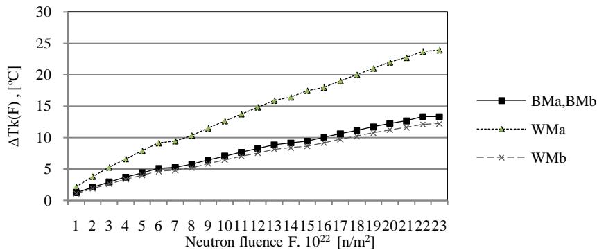 Figure 4: Function
$\Delta T_{K}(F)$ for Base Metal BM and Weld Metal WM of the RPVs, units "a", "b"
The critical temperature shift values $\Delta T_{K}(F)$ grow proportionately to the increase of the fluence F values, both in the base, and the weld metal. The $\Delta T_{K}(F)$ curves for base metal (BMa and BMb) coincide because $A_{F}$ does not depend on the chemical composition of the base metal. Difference can be observed in the neutron embrittlement rate of weld metal
(WMa and Wmb); greater embrittlement rate was found for WMa. Regarding RPVb, the curves $\Delta T_{K}(F)$ for base metal, BMb, and weld metal, WMb, almost tally.
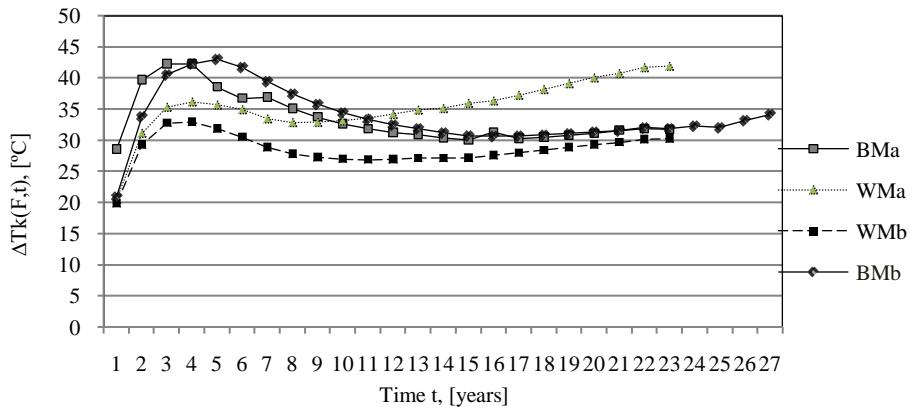
The critical temperature shift resulting from thermal ageing $\Delta T_{K}(t)$ of base metal and welded metal (BMa, BMb, WMa, WMb), is shown in "Figure 5".
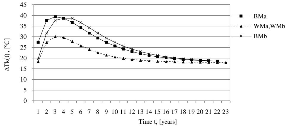
Figure 5: $\Delta T_{K}(t)$ function of the Time t for base metal and weld metal of the reactor pressure vessels of units "a" and "b"
The curves' trend (behavior of the curves) for the thermically induced part $\Delta T_{K}(t)$ for base metal (BMa, BMb) anticipates the trend of the curves for weld metal (WMa, WMb). A peak can be observed for the thermal embrittlement values over a period of 2-5 years, following which the thermal embrittlement drops sharply. After the first 10-11 years of operation, the function $\Delta T_{K}(t)$ has almost unchangeable value, and this trend is preserved over the further operating period of the metal, both welded and base metal.
The sum of the critical temperature shifts caused by neutron and thermal ageing is:
$$
\Delta T _ {K} (F, t) = \Delta T _ {K} (F) + T _ {K} (t) \tag {5}
$$
The function $\Delta \mathrm{T}_{\mathrm{K}}(F,t)$ for base metal and weld metal is shown in "Figure 6".
 Figure 6: Embrittlement (Neutron and Thermal) for base Metal BM and Weld Metal WM The
$T_{K}(F,t)$ Function of T time
The thermally induced embrittlement is dominant in the first 10 years of an NPP operation, after which the neutron embrittlement is prevalent. In the beginning of NPP operation the embrittlement rate of base metal BMa, BMb prevails over that of the welded metal WMa, WMb. This is followed by process reversal, i.e., prevalence of weld metal embrittlement.
A comparative analysis was conducted of the critical temperature shift values $T_{K}(F,t)$. Comparison was made between 1) $T_{K}(F,t)$ as calculated with the fluence value of the neutron detectors, and 2) $T_{K}(F,t)$ obtained on the basis of experimental data from the surveillance specimens (SS). The results are demonstrated on "Figure 7", a) base metal BM and b) weld metal WM.
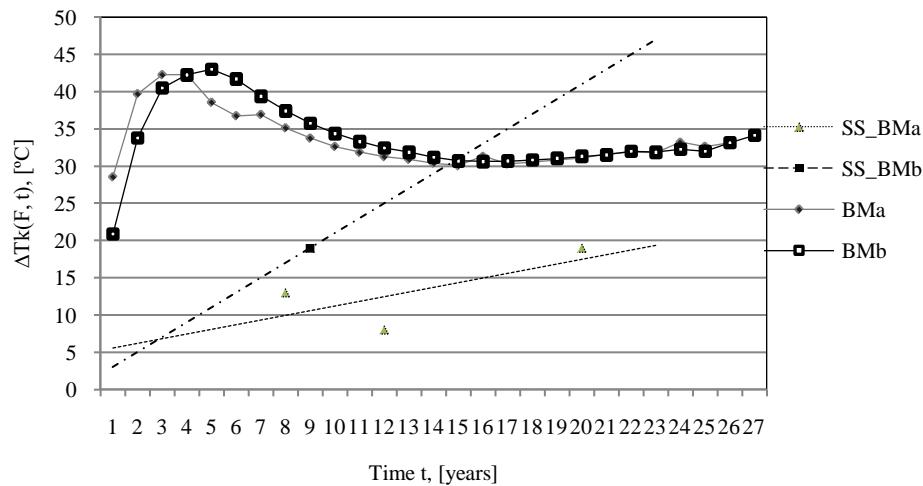
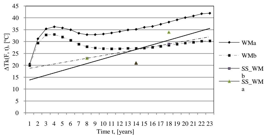 Figure 7: Function
$T_{K}(F,t)$ of Time t for a) Base Metal BM (above) and b) Weld Metal WM. Averaged Line based on the Experimental Data from the Surveillance Specimens for a) Base Metal BM and b) Weld Metal WM For base metal - the calculated results are higher than the experimental ones. The $T_{K}(F,t)$ function trend exceeds the values of the experimentally obtained data from the surveillance specimens of unit "a" base metal BMa, contrary to the case with base metal BMb.
For weld metal WMa, the trend curve $T_{K}(F,t)$, based on the calculations is high and quickly grows proportionally to the operating time (running hours) increase. The trend curve $T_{K}(F,t)$ for WMb (almost) coincides with the averaged line based on the experimental data.
The RPV metal resistance to neutron and thermal impacts is evaluated by means of the values of $T_{K}(F,t)$ - cold embrittlement critical temperature. With the increase of the neutron fluence value $F$ and of the accumulated running hours, $t$, the values of $T_{K}(F,t)$ become higher. The values of $T_{K}(F,t)$ shall be regularly compared against the normative and the design specifications. This a main requirement of the technical specifications for safe operation of the reactor equipment. With $T_{K}(F,t) < T_{\text{margin}}$ (margin value), resistance of the reactor pressure vessel metal to neutron and thermal impacts has been achieved.
1) The calculated and the experimentally obtained values of $T_{K}(F, t)$ show that the critical embrittlement temperature shift is less than $T_{\text{margin}} = 57^{\circ} \text{C}$. Therefore, the requirement for resistance of the RPV metal to neutron and thermal impacts has been satisfied for units "a" and "b".
2) The curve $T_{K}(F,t)$ trend for welded metal with higher content of Ni exhibits the greatest dynamic. It can be concluded that these welded joints (unit "a") are the most critical element of the reactor. This inference is confirmed by the match between the calculated and the experimentally obtained data for $T_{K}(F,t)$.
3) Regarding base metal, a good match was obtained between the calculated data for units "a" and "b". The experimental data from the surveillance specimens testing demonstrated lower values for the lifetime characteristics $T_{K}(F,t)$.
### b) Study of the RPV ageing metal due to corrosion-erosion wear
The RPV metal, both on the inside and on the outside surfaces can be tested (controlled) through scanning using a remote system for visual inspection. The periodicity of this activity is once in 4 years, as specified in the technical specifications (for operation of the nuclear power unit). If needed, this period can be shorter. The visual inspection method enables detecting and diagnosing surface discontinuities on the RPV inner surface. The controlled parameters are: presence or absence of discontinuities, their type, size and location [23].
To examine metal for corrosion-erosion (ageing) wear, remotely operated visual inspection is implemented. An underwater camera system is used to examine the RPV; A special software serves for storing data on the location of indications, sizing, comparing with previous data.
The input data for the studies are the parameters of discontinuities found on the inner surface of the RPV and include, as follows: 1) type of discontinuities as classified according to a standard, 2) discontinuities' location and coordinates in the metal,3) size of discontinuities, 4) orientation of the discontinuities.
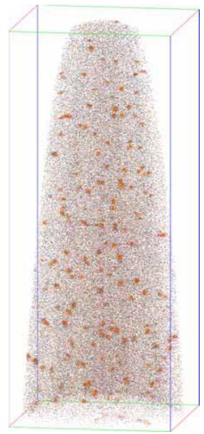
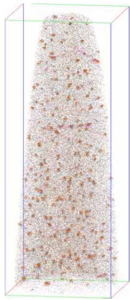
The data of the discontinuities found on the RPV surface were entered in a data basis and systematized. Following 15-17 years from the first start-up of a reactor unit, the first discontinuities in the metal structure (that may actually be detected by inspection methods) can be observed on the inner surface of the reactor pressure vessel. With the progress of the unit's operating course, local merges of discontinuities can be observed. Corrosion-erosion foci are formed, concentrated in the fretting area of the strengthening nodes of the reactor internals, as is shown on "Figure 8". Single surface defects are observable; the defect parameters get determined.
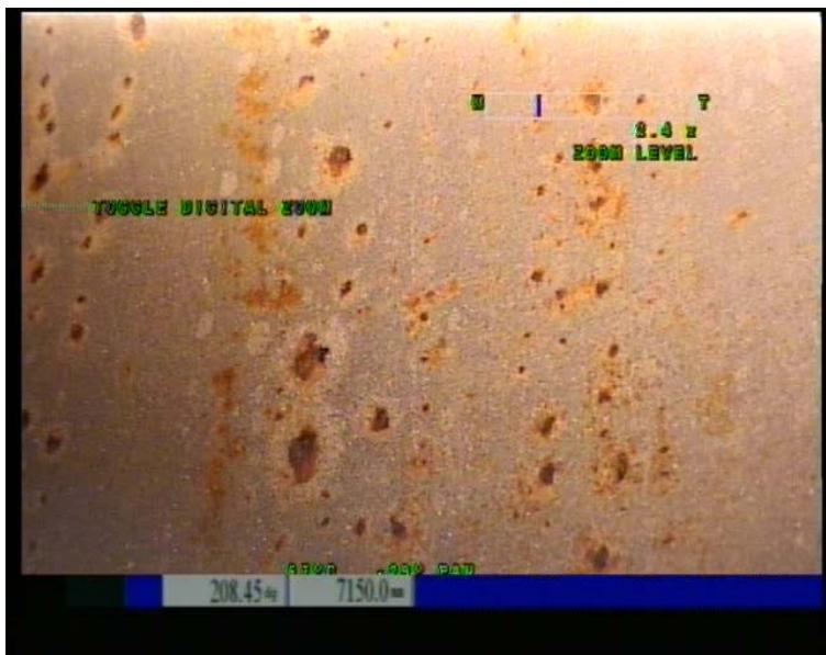 Figure 8: Discontinuities on the Inner Surface of the Reactor Pressure Vessel
The corrosion rate is one of the ageing effect indicators. The corrosion rate monitored indicators were:
- Beginning of the occurrence of corrosion outbreaks; The data on this indicator are decisive for the start of monitoring of the area.
- Changes in the size of the discontinuities monitored.
- Occurrence of new defects.
The periodicity of this inspection is specified in the technical specifications for operation of the nuclear power unit. Usually, it is once in 4 years. However, each NPP may alter it at its own discretion.
The respective parameters are identified for each defect and each group of defects. Each assessment of the parameters is followed by an analysis of the acceptability of the defects in terms of the normative requirements [23, 24]. The analytical part of the activity can offer recommendations of the future operation of the reactor equipment. Normally, these recommendations regard, as follows:
- Mechanical activities - the reactor internals shall be positioned in a way so as to prevent mechanical scratching, scuffing, denting, etc.
- The water chemistry shall be more benign to the surfaces.
c) Study of RPV Metal Embrittlement Resulting from Occurrence of a Discontinuity
The metal on the inside of the reactor pressure vessel shall be tested (controlled) once every four years (as required by normative regulations). In case defects are present or indications of defects, it is recommended that this interval be shorter. Visual inspection, penetrant testing and UT are the control methods usually applied by means of remotely controlled scanning technical tools. Non-destructive examination methods enable finding any discontinuities (defects, cracks) and studying their parameters, i.e., location, type, size, orientation.
At the places where discontinuities have been found studies are performed to identify the environmental load factors, what their values are, and whether they change with the varying design operational modes of the reactor unit. The operating conditions (for the inner surface metal) are characterized by intensive neutron flux with neutron energy exceeding 1.5 MeV; high pressure values (up to 17.5 MPa; and high temperatures of the primary circuit fluid $(323^{\circ}\mathrm{C})$.
Evaluations are conducted on the impact of the loads on the evolution of the defects. The discontinuities are studied by the visual inspection and ultrasonic testing, while the studied parameters are location, type and size (area). The input data of this study cover data of the defects and of the loads in effect:
- The defects indications data include: location, type, size $(a, c)$, distance $b$ from the internal surface of the reactor pressure vessel. The data for the defects and defect indications result from applying the nondestructive examination methods.
- Data of the neutron fluence are collected on an annual basis by monitoring the readings of the neutron detectors (reactor internal ones). Another data source are surveillance specimens that are withdrawn from the RPV and tested according to a dedicated program.
- Data of the active stresses can be obtained from the RPV datasheet and/or strength analyses of the manufacturer (conducted on unit "a").
- The load factors in the zone where defects occurred can be obtained, as follows:
- From the readings of neutron fluence detectors for the inner surface of the RPV;
- The active stresses values are obtained from the strength analyses (calculations) and equipment datasheets.
A graphical presentation method is implemented to demonstrate the neutron fluence distribution on the inner surface of the RPV metal. A coordinate system is used. Along the "x" axis the coordinates of the RPV inner surface are marked (x=0 indicates a location on the innermost layers of the reactor); the fluence values are shown on the "y" axis. The graphic representation method visualizes the fluence distribution along the thickness of the reactor wall.
Using a graphic method, the distribution of circular stresses is shown as depending on the distance "X" from the border of the deposit weld metal with the base metal of the RPV inner surface. Similarly, a graphic method is used to demonstrate the distribution of thermal stresses as dependent on the distance $X$ from the border of the deposit weld metal with the base metal.
Selection of defects means the parameters of all the identified discontinuities are reviewed. An assessment is made to decide which of them are located in zones with a degradation potential. Large size defects present particular danger. The discontinuities located close to the inner surface of the RPV are considered to be subject to the comprehensive impact of the working environment loads inside the pressure vessel, i.e., high values for the neutron fluence and thermohydraulic loads. The discontinuities that have an opening to the RPV inner surface present a hazard for occurrence of intracrystalline (intergranular) corrosion, stress corrosion, etc. Of great significance is the orientation of the discontinuity with regard to the direction of the active loads; the most dangerous are the type A stresses (crack resistance).
Several of the "most dangerous" discontinuities are selected and calculations are made about them. For each of the selected discontinuity calculations are made to obtain: 1) the values of the stress intensity factor, and 2) the critical values of the stress intensity factor.
Brittle fracture toughness is ensured if the following condition is met with regard to the discontinuity found [19]:
$$
K _ {I} \leq \left[ K _ {I} \right] _ {i} \tag {6}
$$
$$
K_{I} = Y.\sigma_{k}.\sqrt{a}
$$
where $\sigma$ stands for the load, and $Y$ is a coefficient related to the discontinuity shape, $a$ is the small semi-axis of the discontinuity, as is shown on the "Figure 9".
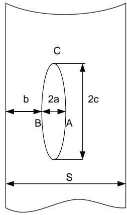 Figure 9: A diagram of a below-surface discontinuity; a - small semi-axis.
For a below-surface discontinuity in point A, of "Figure 9":
$$
Y = \frac{1.79 - 0.66.\left(\frac{a}{c}\right)}{\left[ 1 - \beta^{1.8}.\left(1 - 0.4.\frac{a}{c} - 0.8.\gamma^{0.4}\right) \right]^{0.54}}
$$
$$
\beta = \frac {a}{a + b}; \gamma = 0. 5 - \frac {a + b}{S}; b + a \leq \frac {S}{2}
$$
$$
\sigma_ {k} = \frac {3 \sigma_ {A} + \sigma_ {B}}{4} + \frac {(\sigma_ {A} - \sigma_ {B}) . \left(\frac {a}{c}\right)}{1 2}
$$
For a below-surface discontinuity in point $B$, of "Figure 9":
$$
Y = \frac{1.79 - 0.66.\left(\frac{a}{c}\right)}{\left[1 - \beta^{1.8}.\left(1 - 0.4.\frac{a}{c} - \gamma^{2}\right)\right]^{0.54}}
$$
$$
\sigma_ {k} = \frac {\sigma_ {A} + 3 . \sigma_ {B}}{4} + \frac {(\sigma_ {A} - \sigma_ {B}) . \left(\frac {a}{c}\right)}{1 2}
$$
For a surface discontinuity in point A, of "Figure 9":
$$
Y = \frac{2 - 0.82 \left(\frac{a}{c}\right)}{\left[ 1 - \left(0.89 - 0.57 \cdot \sqrt{\frac{a}{c}}\right) ^ {3} \cdot \left(\frac{a}{s}\right) ^ {1.5} \right] ^ {3.25}}
$$
$$
\sigma_{k} = 0.61.\sigma_{A} + 0.39.\sigma_{B} + \left[ 0.11.\frac{a}{c} - 0.28.\frac{a}{s}.\left(1 - \sqrt{\frac{a}{c}}\right) \right].(\sigma_{A} - \sigma_{B})
$$
For a surface discontinuity in point B, of "Figure 9":
$$
Y = \frac{\left[ 2 - 0 . 8 2 . \left(\frac{a}{c}\right) \right] . \left[ 1 . 1 + 0 . 3 5 . \left(\frac{a}{s}\right) ^ {2} . \sqrt{\frac{a}{c}} \right]}{\left[ 1 - \left(0 . 8 9 - 0 . 5 7 . \sqrt{\frac{a}{c}}\right) ^ {3} . \left(\frac{a}{s}\right) ^ {1 . 5} \right] ^ {3 . 2 5}}
$$
$$
\sigma_ {k} = 0. 1 8. \sigma_ {A} + 0. 8 2. \sigma_ {B}
$$
For welded joints:
$$
\left[ K _ {I} \right] = 25 + 27.\exp 0.0235.\left(T - T _ {K}\right) \text{inhydraulictestsmode} \tag{8}
$$
$$
\left[ K _ {I} \right] = 35 + 53.\exp 0.0217.\left(T - T _ {K}\right) \text{inaccidentconditions} \tag{9}
$$
The study was conducted over the years 1993 - 2014.
Remotely operated equipment for visual inspection and ultrasonic testing scanning type of equipment that permits sequential sounding of all parts of the reactor pressure vessel (object of control). The sounding (a signal is input in the metal and then the reflected signal is registered) is remotely operated. Software instrumentation is employed to register the results. All identified images for defect indications are stored in the memory, their size is taken as well as coordinates. To complete this activity a UT system, type P-scan, for the RPV inner surface is used together with a type Tomoscan system.
The results are obtained using the following algorithm:
1) Regular, periodic non-destructive examination of the reactor pressure vessel is conducted implementing inspection methods, i.e., remote visual inspection and ultrasonic testing). This NDE is held once every 4 (four) years.
2) If indications of discontinuities have been found, their parameters shall be identified, i.e., length, location and size of equivalent area (UT characteristics of the indications).
3) If discontinuities have already been found during preceding NDE campaigns, the discontinuity indications' parameters are measured again.
4) A data base is established and the indications' data are input in it following each NDE of the RPV.
5) The data of the discontinuity indications are arranged by 1) size of the length, 2) area, 3) location, 4) the RPV operating period (in years). The location of the indications in the RPV metal is registered in a 3-D coordinate system - height, RPV length and depth of embedding in the metal, as read from the RPV inner surface.
6) A screening of the discontinuities is performed for the purpose of further assessments and calculations. The indications having the largest area have their location tracked in terms of the distance from the RPV inner surface. The location is an important factor as the values of the fluence and the thermohydraulic loads tend to change in the different points of the RPV.
7) A graphic method is implemented to demonstrate the neutron fluence distribution on the inner surface of the RPV metal.
8) As regards the fixed locations of the indications (critical zones), the circular stresses and temperatures are considered under the different operating modes of the reactor unit. To ensure conservatism of the calculations, the highest values are used for: 1) circular stresses, 2) temperatures under all the design modes.
9) The number of years elapsed since the start of operation of the pressure vessel are taken into account. The operating period is important for the evolution of the discontinuities - whether the thermal embrittlement or the neutron one have greater impact, insofar as these influences can be considered separately in the analyses.
10) Calculations are made of the stress intensity factors $K_{I}$ for selected indications. The critical temperature shift $\Delta T_{K}(F,t)$ is calculated using two methods: 1) according to the strength norms [19] and 2) according to the European documents [11].
11) Calculations are made for the critical values of the stress intensity factors $K_{I}$.
12) The results obtained for the stresses intensity factors $\mathbf{K}_I$ are compared with the critical ones $[K_I]$, as in "Equation (6)".
A graph has been prepared demonstrating the distribution of the relative values of the neutron fluence along the depth of the RPV, as shown in "Figure 10".
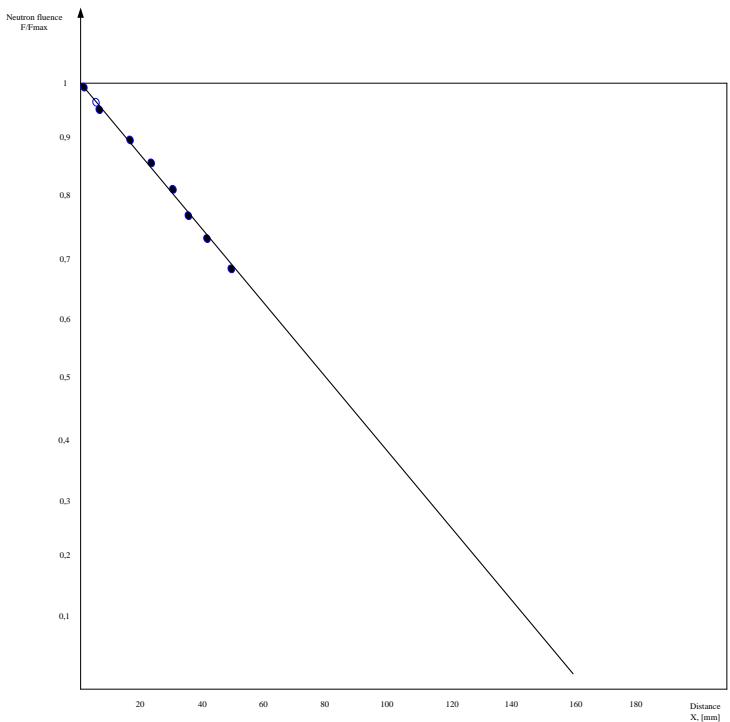 Figure 10: Distribution of the Relative Values of the Neutron Fluence
$F / F_{\max}$ on the Inner Metal Surface of the Reactor Pressure Vessel
Non-destructive visual inspection and ultrasonic testing were performed. The indications parameters, such as size, location coordinates, year of size taking, were assessed. The data of a welded joint indications and the relative values of the neutron fluence $F / F_{\max}$ are shown in "Table 2".
Table 2: Indications of Welded joint 2 of the Reactor Pressure Vessel - Sizes, Coordinates and Neutron Flux at the Position of the Indicates
<table><tr><td rowspan="2">Indication No</td><td colspan="6">Size and coordinates: a) Along the weld.
b) Along the reactor height.
c) In depth of the weld, on the outside.</td></tr><tr><td>1</td><td>2</td><td>3</td><td>4</td><td>5</td><td>6</td></tr><tr><td>Size [mm]</td><td>478</td><td>39</td><td>39</td><td>150</td><td>55</td><td>27</td></tr><tr><td>a) [grad]</td><td>64.4</td><td>79.9</td><td>85.4</td><td>88.4</td><td>104.9</td><td>107.4</td></tr><tr><td>b) [mm]</td><td>274.5</td><td>276.3</td><td>277</td><td>276.7</td><td>276.8</td><td>277</td></tr><tr><td></td><td>520</td><td>52</td><td>53.7</td><td>51.4</td><td>51.6</td><td>50.6</td></tr><tr><td>Neutron flux F/Fmax</td><td>0.15</td><td>0.15</td><td>0.15</td><td>0.15</td><td>0.15</td><td>0.15</td></tr></table>
Indications were identified at two more welded joints of the reactor pressure vessel. To forecast the development of the discontinuity's indications in the metal, the typical transitional state of "Accident conditions - Primary circuit large leak" has been considered. Pursuant to the register of the implemented operational cycles, the large leak mode is associated with the highest amplitude values for stress-temperature fields.
Figure 11" demonstrates the relative distribution of circular stresses as dependent on the distance X from the border of the deposit weld metal with the base metal.
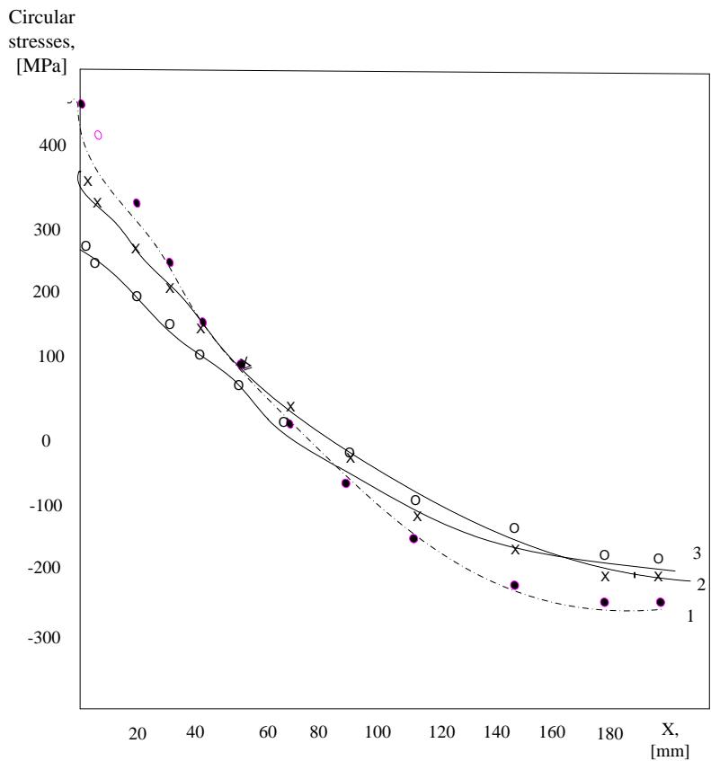 Figure 11: Relative Distribution of Circular Stresses as Dependent on the Distance X from the Border of the Deposit Weld Metal with the Base Metal.
$X = 0$ is the Position that is Closest to the Inner Surface of the RPV; the Active Stresses have Maximum values. Curve 1 – at the Moment of 0.2 hrs of the Time Interval of the Mode; Curve 2 – at 0.4 hrs; Curve 3 – at 0.6 hrs
"Figure 12" shows the temperature distribution in the RPV metal depending on the distance "X" from the border of the deposit weld metal with the base metal.
Temperature, $^\circ \mathrm{C}$
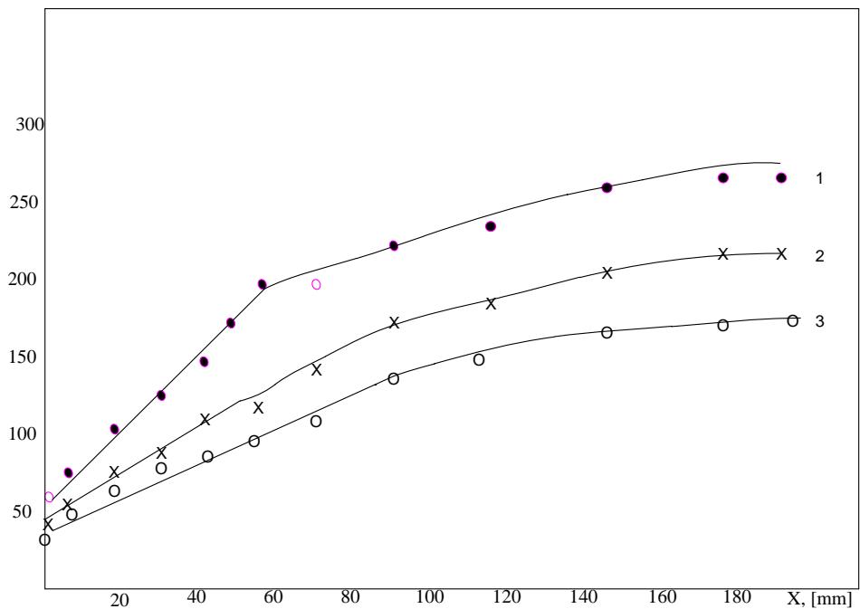
Figure 12: Temperature distribution in the pressure vessel metal as dependent on the distance X from the border of the deposit weld metal with the base metal. Primary circuit large leak mode: Curve 1 – at the moment 0.2 hrs of the time interval of the mode; curve 2 – at 0.4 hrs; curve 3 – at 0.6 hrs
The values of the circular stresses and the temperature at the locations of discontinuities are provided in "Table 3" and "Table 4".
Table 3: Stresses Values at the Locations of Discontinuities ${\sigma }_{\theta \mathrm{{BH}}}$ - Circular Stresses of the Base Metal Inner Surface
<table><tr><td rowspan="2">Weld joint/IndicationNo</td><td colspan="3">Distribution of circular stresses at the locations of discontinuities for the"Primary circuit large leak" mode, σθBH [MPa]</td></tr><tr><td>0,2 hrs</td><td>0.4 hrs</td><td>0.6 hrs</td></tr><tr><td>2/I</td><td>-210</td><td>-170</td><td>-160</td></tr><tr><td>2/II</td><td>-210</td><td>-170</td><td>-160</td></tr><tr><td>2/III</td><td>-210</td><td>-170</td><td>-160</td></tr><tr><td>2/IV</td><td>-210</td><td>-170</td><td>-160</td></tr><tr><td>2/V</td><td>-200</td><td>-175</td><td>-160</td></tr><tr><td>2/VI</td><td>-240</td><td>-190</td><td>-180</td></tr><tr><td>3/I</td><td>487</td><td>350</td><td>260</td></tr><tr><td>3/ II</td><td>-80</td><td>-175</td><td>-150</td></tr><tr><td>3/III</td><td>-110</td><td>10</td><td>-35</td></tr><tr><td>3/IV</td><td>-250</td><td>-190</td><td>-185</td></tr><tr><td>4/I</td><td>450</td><td>140</td><td>130</td></tr><tr><td>4/II</td><td>210</td><td>250</td><td>200</td></tr><tr><td>4/III</td><td>-200</td><td>-115</td><td>-120</td></tr></table>
Table 4: Temperature Values at the Locations of Discontinuities.
<table><tr><td rowspan="2">Weld joint/Indication No</td><td colspan="3">Distribution of temperature in the RPV metal for the "primary circuit large leak" mode, [°C]</td></tr><tr><td>0,2 hrs</td><td>0.4 hrs</td><td>0.6 hrs</td></tr><tr><td>2/I</td><td>260</td><td>180</td><td>158</td></tr><tr><td>2/II</td><td>260</td><td>180</td><td>158</td></tr><tr><td>2/III</td><td>260</td><td>180</td><td>158</td></tr><tr><td>2/IV</td><td>260</td><td>180</td><td>158</td></tr><tr><td>2/V</td><td>260</td><td>178</td><td>150</td></tr><tr><td>2/VI</td><td>250</td><td>190</td><td>160</td></tr><tr><td>3/I</td><td>70</td><td>55</td><td>45</td></tr><tr><td>3/ II</td><td>240</td><td>177</td><td>145</td></tr><tr><td>3/III</td><td>210</td><td>160</td><td>130</td></tr><tr><td>3/IV</td><td>250</td><td>190</td><td>167</td></tr><tr><td>4/I</td><td>150</td><td>110</td><td>70</td></tr><tr><td>4/II</td><td>108</td><td>65</td><td>60</td></tr><tr><td>4/III</td><td>240</td><td>170</td><td>140</td></tr></table>
For the purpose of this study, calculations were made of the stress intensity factors $K_{I}$ under accident conditions and "primary circuit large leak" mode. The stress intensity factor, a below-surface discontinuity is calculated with the "Equation (7)".
A screening was performed to select the discontinuities have to represent the worst-case scenario. Two indications were chosen of weld joint No 2 that are largest in size compared with the rest of discontinuities identified, and are located in areas where high temperature of the metal is expected in the primary circuit large leak mode. Also, an indication of welded joint No 3 was singled out as it was large in size and was located in close proximity to the inner surface of the RPV. The stress intensity factors K were calculated for selected indications. The results for the calculations of $K_{I}$ are provided in "Table 5".
Table 5: The Results for the Calculations of ${K}_{I}$ Under Emergency Condition,Primary Circuit Large Leak Mode
<table><tr><td rowspan="2">Weld joint/Indication No</td><td colspan="3">K1in point A, circular stress, under emergency condition, primary circuit large leak mode, [MPA.√m]</td></tr><tr><td>0,2 hrs</td><td>0.4 hrs</td><td>0.6 hrs</td></tr><tr><td>2/I</td><td>21.02</td><td>17.02</td><td>16.02</td></tr><tr><td>2/IV</td><td>23.8</td><td>19.2</td><td>18.1</td></tr><tr><td>3/I</td><td>60.21</td><td>43.27</td><td>32.14</td></tr></table>
Calculations were made of the limit values of the stress intensity factors $[K_I]$ under emergency condition, primary circuit large leak mode. "Table 6" contains the results about indication No 1 of welded joint No 3.
Table 6: The Results for the Calculations of $K_I$ and $[K_I]$, under Emergency Condition, Primary Circuit Large Leak Mode
<table><tr><td rowspan="2">Weld joint/Indication No</td><td colspan="3">K1in point A, circular stress, under emergency condition, primary circuit large leak mode, [MPA.√m]</td></tr><tr><td>[K1]</td><td>[K1] per [19]</td><td>[K1] per [11, 25]</td></tr><tr><td>3/I</td><td>60.21</td><td>108</td><td>123</td></tr></table>
For Indication No1 of welded joint No3 a comparison was made between the current values of the stress factor and the limit value[]
$$
K = \{6 0, 2 1; 4 3, 2 7; 3 2, 1 4 \} < [ ] = \{1 0 8, 1 2 3 \}
$$
Meeting the condition of "Equation (6)" is a regulatory criterion that fracture of the weld joint will not occur as a result of brittle fracture due to the present discontinuity in case of accident conditions, with primary circuit large leak mode.
## VI. CONCLUSIONS
Currently, metal ageing issues have been gaining increasing topicality as the equipment in most of the operating Nuclear Power Plants is already "aged", and although a good deal of knowledge has been accumulated on NPP components ageing, it is becoming clear that there are still a great many unexplored areas.
NPP equipment and components are subject to the continued impact of stress factors. The mechanisms of the mechanical properties' degradation of WWER reactor type metal components are corrosion, erosion, neutron and thermal ageing, fatigue and wear. These impacts induct changes in the mechanical properties of metal and, eventually, result in the component's loss of operability. The latter could compromise the NPP safety and also cause economic losses due to generation losses.
The degradation mechanisms of mechanical properties have been individually researched into a laboratory conditions, while materials in NPP are subjected to integrated impact of load factors. In general, the proposed lifetime characteristics assessment methodologies are based on the independent occurrence of processes such as corrosion, fatigue, creep and neutron embrittlement, although in reality these processes run simultaneously in various combinations [26].
The paper proposes a methodology for study of ageing effects. A case is presented of implementation of the methodology for assessment of ageing effects of reactor pressure vessels. The RPV is subject to the impact of multiple load factors.
Of all the degradation mechanisms that affect the RPV, the radiation and neutron fluence thermal impacts are the most destructive ones. Over the first decade of an NPP operation, thermal embrittlement is dominant, followed by neutron embrittlement. The nickel (Ni) content enhances the embrittlement trend which is manifested in the growing value of the embrittlement temperature shift. Greater embrittlement occurs in weld metal than in base metal.
The evaluation of the ageing effects points out that one of the greatest hazards for the integrity of the reactor pressure vessel is the presence of a defect/defects on account of them posing the possibility for brittle fracture. The following cases of RPV metal defects were studied: 1) surface defects of base metal; 2) defects of weld joints in the maximum neutron fluence areas (dominant factor); 3) defects in areas with high values of stress and temperature (dominant factor).
Based on the studies performed it can be concluded that case 2) poses the greatest hazard.
Defects in metal on account of equipment ageing occur following a long term of operation. Before extending the NPP lifetime it is required to confirm the operability of components. Equipment condition investigation is a challenge since, clearly, one cannot destroy non-replaceable equipment of an NPP in operation in order to examine its degree of degradation. Therefore, it is important to track the manifestation of ageing effects throughout all stages of NPP operation.
### ACKNOWLEDGMENT
The scientific research, the results of which are presented in this publication, were financed by the internal competition of TU-Sofia-2023
Generating HTML Viewer...
References
20 Cites in Article
Robert Krivanek,Jan Fiedler (2017). Main corrective measures in an early phase of nuclear power plants’ preparation for safe long term operation.
Oao Okb Gidropress (2012). General program for comprehensive assessment of the actual condition and assessment of the residual lifetime of SSGs at Kozloduy NPP.
K Dolganov,V Semenov,A Kiselev,D Tomashchik,A Fokin,V Astakhov,A Nikolaeva,D Gasparov,S Pantyushin,N Bukin,M Bykov (2013). Method for evaluation of loads on VVER‑1200 reactor pressure vessel from in-vessel steam explosions.
Ageing Management for NPPs.
Laurie Grzesiak (2009). Fayet Héloïse / Férey Amélie, « “Imaginer au-delà de l’imaginaire”. Red teaming et serious games au service de l’anticipation et de la prospective », Briefings de l’IFRI, 30 mars 2023, IFRI (Institut français des relations internationales), 14 p. URL : https://www.ifri.org/sites/default/files/atoms/files/briefing_red-teaming-wargames_fayet-ferey_mars2023.pdf/ . Consulté le 31 mai 2023.
(2015). Long Term Operation of Nuclear Fuel Cycle Facilities.
U (2001). Public comments on the proposed 10 CFR Part 51 rule for renewal of nuclear power plant operating licenses and supporting documents: Review of concerns and NRC staff response. Volume 1.
R Gopalakrishnan (2014). Summary of IAEA safety standards series no. SSG-42: Specific Safety guide on 'safety of nuclear fuel reprocessing facilities' (May 2017).
Not Author (2015). Class 2 nuclear components (supplement to ASME Boiler and Pressure Vessel Code, Section III, Subsections NCA and NC).
(2019). Leadership and Management for Safety.
M Georgiev (2005). Crack resistance of metals under static load.
Naoki Soneda,Kenji Dohi,Akiyoshi Nomoto,Kenji Nishida,Shiori Ishino (2010). Embrittlement Correlation Method for the Japanese Reactor Pressure Vessel Materials.
Ivan Balashov,Roman Sydorchuk,Viktor Skoropadskyi,Volodymyr Ustymenko (1989). USE OF HYDRO-REMOVAL ASH FOR PREPARATION OF CRUSHED AND SAND MIXTURES, IN COMBINATION WITH MINERAL BINDERS AND COMPOSITIONS FOR ARRANGEMENT OF PAVEMENT BASE.
Milan Brumovsky (2014). Principal Bases of the VERLIFE – Unified Procedure for Lifetime Assessment of Components and Piping in WWER NPPs During Operation.
J Collins (1993). Failure of materials in mechanical design: analysis, prediction, prevention.
G Dimova (2015). Ndt and safety.
V Dmitrik,S Bartash (1989). Peculiarities of degradation of metal of welded joints of steam pipelines of heat power plants.
R Eo (2005). Procedure to calculate for the resistance brittle failure of the VVER Nuclear Reactor Vessels during operation (MRKR-SKhR-2005.
G Dimova (2021). Methodology for lifetime characteristics assessment of mechanical equipment in nuclear power plants. Ageing management of NPP mechanical equipment.
Explore published articles in an immersive Augmented Reality environment. Our platform converts research papers into interactive 3D books, allowing readers to view and interact with content using AR and VR compatible devices.
Your published article is automatically converted into a realistic 3D book. Flip through pages and read research papers in a more engaging and interactive format.
Our website is actively being updated, and changes may occur frequently. Please clear your browser cache if needed. For feedback or error reporting, please email [email protected]
Thank you for connecting with us. We will respond to you shortly.