At present the formation of flocculent suspension and its gravity separation are lengthy processes varying between 3 and 4.5 hours. Consequently this results in high capital costs. Therefore, reconsideration of the kinetics of formation of the flocculent suspension and its effect on the gravity separation of formed suspension was needed. This reconsideration revealed that an unconventional, open-minded thinking was required to develop a new water purification technology capable of solving this problem. This technology will most likely be in direct disagreement with the traditional way of thinking in water purification engineering. The reconsideration project also revealed that the current method for the use of water soluble polymers results in a deterioration of the purified water quality and detrimentally affects the operation of filters. Therefore the development of a method for using these polymers, free of side effects, is also essential. A new technology, the High Rate Clarification Technology, combining two processes developed for addressing the above shortcomings, was developed.
## I. INTRODUCTION
The traditional method for the way of formation of flocculent suspension and its gravity separation are lengthy processes varying between 3 and 4.5 hours. This requires construction of large waterworks on large lands, resulting in higher capital costs. The need to reduce the high capital costs of waterworks received appropriate attention many years ago. This required re-evaluation of the kinetics of formation of flocculent suspension and its effect on the gravity separation. The outcome highlighted the fact that the formation of flocculent suspensions under a commonly low agitation intensity and their gravity separation required an unreasonably long time. This is because the formed aggregates are large, heterogeneous, light in size and of a very low sedimentation velocity. Furthermore, it also showed that the water soluble polymers applied, in accordance to common practice, as coagulant and, or flocculant aids, do not facilitate the formation of rapidly settling aggregates. Instead, they adversely affect both the quality of purified water and the operation of filters by increasing the rate at which filter head-loss rises.
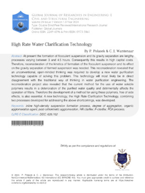
The outcome of the above re-evaluation showed that a non-traditional open-minded thinking was needed to develop a new water purification technology. Such technology that will be able to solve these problems would probably have to be in direct disagreement with the traditional way of thinking in water purification engineering. Such new technology, the High Rate Clarification Technology (HRCT), was developed [1, 2]. It consists of two developed processes, namely the Inline High Density Suspension (IHDS) formation process producing dense micro-aggregates and the Post-Orthokinetic Agglomeration (POA) process agglomerating the micro-aggregates to large, heavy, rapidly settling agglomerates. The impact of HRCT on the acceleration of the sedimentation velocity of formed agglomerates is evident from Figure 1.
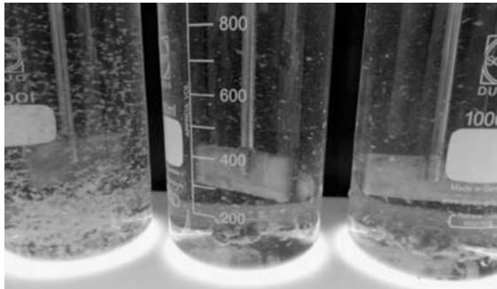 Figure 1: Suspension formed by the High Rate Clarification Technology – anionic polymer dosages from left to right: 0.1; 0.2 and 0.3 mg.L-1, picture taken at a stirrer speed of 27 RPM
The HRCT has not been described before and is presented now by this article. The principles of High Rate Clarification Technology including the method for the most effective application of water soluble polymers are described under Technological Background. The High Rate clarifiers, incorporating the HRCT, were also developed. The performance results achieved at different localities under different applications are described under the Chapter Design, Operation and Performance of High Rate Clarifiers.
The quality of purified water, to a large extent, is influenced by the type of coagulant used; hydrolyzing coagulants (salts of $\mathrm{Al}^{3+}$ and $\mathrm{Fe}^{3+}$ ), if applied under the optimized reaction conditions pertaining to all monitored impurities [3], are capable of purifying water to a quality within the limits defined in the National Standard for drinking water. During this project it was established that the organic coagulants, i.e. water soluble cationic polymers, are not capable of purifying water to the quality attainable by the hydrolyzing coagulants [4-7]. Therefore, the organic coagulants are not an equivalent replacement for the hydrolyzing coagulants.
Particles of impurities consist of two size-fractions, namely the separable and the non-separable particles [8-10]. The total content of particles of impurities is the sum of the content of particles of these two size-fractions. The purpose of water purification is to change the non-separable particles to separable aggregates and then to remove the formed flocculent suspension from the water. The total residual concentration of each monitored impurity determines the overall process efficiency attained by the plant; the residual concentration of non-separable particles determines the process efficiency attainable by the technology used.
## II. TECHNOLOGICAL BACKGROUND
### a) Formation of Aggregates
There are two different opinions about the importance of agitation intensity on aggregation. The first traditional opinion commonly accepted across the water purification field is that a low (gentle) agitation intensity is required to form large aggregates. For instance, Han and Lawler [11] described the importance of agitation intensity as follows:
- The importance of the velocity gradient $(G)$ has been over-emphasized in the traditional view of aggregation, and $G$ has far less importance than previously thought,
- The velocity gradient $G$, although by no means irrelevant, is relatively unimportant in aggregation.
This means that the agitation intensity actually required is that which is enough to prevent sedimentation of the aggregates being formed.
This opinion is questionable for several reasons. The low agitation intensity is not capable of facilitating continuation of the coagulant dispersion, i.e. the particle destabilization, if this is not completed in the flash mixer. Evidently, the time required to complete coagulation (aggregation) is of no importance. Therefore, the effect of completion of coagulation on the quality of purified water, is also not considered to be of importance.
The aggregates formed by the traditional low agitation intensity $(\overline{G} < 50\mathrm{s}^{-1})$ are heterogeneous and of low density. They are easily affected by extraneous issues like temperature variations, and sun and wind effect. The sedimentation velocity of these aggregates is low and varies over a wide range. Due to this, the sedimentation systems to have an acceptable separation efficiency must be sized for the smallest aggregates required to settle. Therefore, the sedimentation velocity of traditionally designed clarifiers is usually based around $v_{s}\leq 2\mathrm{m.h^{-1}}$.
The other opinion that the agitation intensity is of prime importance in the aggregation is based on Camp [12, 13]. The benefit of high agitation intensity on aggregation in its complexity is described in [1, 14-18].
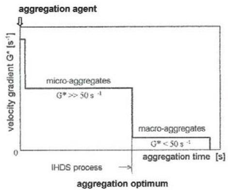 Figure 2: Illustration of the Inline High Density Suspension (IHDS) formation process (
$G^{\star} =$ )
Understanding the significance of the intensity of agitation on the course of the formation of aggregates and their properties led to the development of the Inline High Density Suspension (IHDS) formation process. The formation of aggregates under the IHDS process produces micro-aggregates fairly uniform in size and density. These micro-aggregates can be enlarged to a lower size macro-aggregates using subsequent low agitation intensity (Figure 2).
Different opinions also exist on the method of using the cationic, anionic and nonionic water soluble organic polymers. A common reason for using these different polymers are their dominant adhesion properties which are capable of facilitating the formation of larger and, therefore, a more rapidly settling suspension.
Technologically these polymers are generally used either as the coagulant aids and, or the aggregation aids and applied into a differently progressed aggregation, or as the aggregation agents (coagulants) replacing the traditional mineral coagulants, primarily the hydrolyzing coagulants. These methods have continued in use for more than 50 years [19-21]. This project proved that the cationic polymers, sometimes referred to as organic coagulants, are not an equivalent replacement for the hydrolyzing coagulants [4, 5, 7, 21].
This project also proved that the commonly accepted method for the use of anionic and non-ionic polymers does not effectively facilitate the formation of larger, and a more rapidly settling suspension. The commonly accepted method does not determine the most effective conditions under which these polymers should be applied to accelerate coagulation-aggregation-sedimentation processes and to most effectively improve the purified water quality.
Furthermore, this common method is considered inappropriate because it also produces certain serious shortcomings and side effects, such as:
- The quality of purified water is poorer than that produced without the polymer,
- The increase in the sedimentation velocity of formed suspension seems to be too low in comparison to the relatively high polymer dosage commonly applied,
- The deep-bed filtration is adversely affected if the filters are not designed for the filtration of a polymer formed suspension. The filtration shortcomings result in a rapid build-up of filter head loss causing the filter bed to operate under undesirable subatmospheric pressure, as well as a poorer filter backwashing efficiency, all resulting in the reduced length of the filtration cycle, and the formation of mud-balls; the use of a relatively high polymer dosage used may be one of the major contributors to this problem.
In view of the foregoing the development of a new method for the most effective application of the anionic and non-ionic polymers, became a necessity. This method had to fully utilize the adhesion properties of these polymers, and be free of any detrimental side effects. Therefore, the following aspects of the application of anionic and non-ionic polymers were investigated:
- Significance of the state of aggregation (characterized by the degree of aggregation $\gamma$ ) reached by the aggregation at the point of addition of polymer on the settling velocity of formed agglomerates and the purified water quality,
- Significance of the electrolyte pH at which these polymers are dissolved on their agglomeration capability,
- Effect of the maturation of the polymer solution on its agglomeration capability,
- Effect of the concentration of the polymer solution on its agglomeration capability,
- Effect of hydrodynamic conditions applied to the dispersal mixing of the polymer solution, i.e. its homogenisation throughout the aggregated water,
- Effect of inline dilution of the polymer concentrated stock solution on its agglomeration potential,
- The influence of these polymers on the dosage of the aggregation agent (coagulant).
b) Significance of Velocity Gradient on the Properties of Aggregates
During the aggregation process the destabilized particles combine into primary aggregates. These primary aggregates combine into larger spatial structures and form micro- and macro-aggregates. In these structures, there are lattice spaces filled with water. It is assumed that the total volume of these spaces, as well as the size, structural arrangement and compactness (density) of the aggregates formed are influenced during their formation by the magnitude of adhesion forces and kinetic energy of the colliding particles and the smaller aggregates. This topic is dealt with in [1, 2, 14-16].
## i. Size and Shape
This research showed a significant difference in the character and size of aggregates formed by different mean square root velocity gradient $\overline{G}$. The aggregates formed by a low $\overline{G} < 50\mathrm{s}^{-1}$ are macro-aggregates characterized by an anisotropic shape. The resultant aggregates formed by a higher $\overline{G}$ become micro-aggregates. The micro-aggregates are more spherical, granular and compact in their structure and of a greater uniformity in size and density than the macro-aggregates. This change in the character of aggregates clearly follows from the mechanism of particles joining into aggregates. The maximum attainable size of aggregates decreases with increasing $\overline{G}$, and the uniformity in size and compactness of aggregates increases with aggregation time $T$.
## ii. Inner structure
During aggregation, the ratio of adhesive and tangential forces influences the arrangement of destabilized particles of impurities in the aggregates and thereby their compactness. The significance of the ratio of these forces on the structure of aggregates being formed can be described as follows: When the adhesive forces are incomparably greater than the tangential forces (low $\overline{G}$ ), the particles connect at the point of first contact. The resulting aggregates are large, voluminous and of anisotropic shape; they have a geometrically free, broadly branched, spatial mesh structure. Therefore, they are fragile, with a tendency to fragment. The resulting aggregates contain large volumes of voids filled with water.
In contrast, when the ratio of adhesive and tangential forces is low (high $\overline{G}$ ), the primary aggregates in the forming micro-aggregates slide close to one another until they occupy geometrically the most favourable and energetically the most stable position at which they best resist the influence of the applied agitation intensity. Any extension of the agitation time beyond that corresponding to the completion of aggregation does not improve the resultant compactness of aggregates simply because the primary aggregates in the micro-aggregates are already so close to one another that they cannot get any closer. The resultant micro-aggregates are spherical and very compact with a highly arranged inner structure and resistant to fragmentation. These aggregates have the smallest volumes of voids filled with water.
If the tangential forces are considerably greater than the adhesive forces, the formation of aggregates does not occur.
## iii. Porosity
Similarity exists between the deposition of primary aggregates in the micro-aggregates and the sand grains in a filtration bed. Both are characterized by porosity. In the case of a filtration bed, the porosity changes according to deposition of the sand grains. In the case of flocculent aggregates, the porosity changes according to the velocity gradient $\overline{G}$ and time of its duration. Assuming the filter bed consists of spherical grains of the same diameter, Deb [22] described the dependence of the porosity of the filtration bed on the method of deposition as follows: the tangent planes of spherical grains at the point of their contact form a polyhedron. The most free storage of spheres exists when the polyhedron is a cube and the number of contacts is 6; in this case porosity is $\varepsilon_0 = 0.476$. The tightest deposition of these spheres exists when the tangent planes form a twelve-hedron and the number of contacts is 12; in this case porosity is $\varepsilon_0 = 0.2599$.
Furthermore, the micro-aggregates formed at high $\overline{G}$ and the completion of aggregation were observed to be spherical or close to it. Therefore, the Deb's model described above can be applied to the deposition of the destabilized particles in the primary aggregates and the primary aggregates in the micro-aggregates.
Compactness of the arrangement of the primary aggregates in the micro-aggregates, i.e. their porosity, changes depending on how close the primary particles are one to another in the micro-aggregates and this is influenced by the magnitude of $\overline{G}$. Since the porosity of micro-aggregates gradually decreases with an increasing $\overline{G}$ and $T$ it can be concluded that the attainable porosity can be between $\varepsilon_{MI} = 0.48 - 0.26$ when the most compact micro-aggregates are formed by the IHDS process (Figure 2). Comparison of the porosity of these micro-aggregates with that attainable under the common low intensities of agitation $\varepsilon_{LA} = 0.80 - 0.93$ [23, 24] shows that a great potential exists for densification of aggregates formed by the IHDS method.
## iv. Density
The aggregation produces aggregates of a lower density than that of the particles of impurities from which they are formed. While the density of aggregates is low in comparison to that of water, the aggregates are multifold larger than the particles of impurities. Obviously, the density of aggregates is dependent on the relative content of suspended solids in their structure.
Explanation of the significance of agitation conditions on the inner structure of aggregates and consequently their density is evident from the mechanisms of their formation which is dependent on the ratio of adhesion and tangential forces. As described in the foregoing the aggregates formed at low $\overline{G}$ are anisotropic and contain large volumes of water in their voids. Therefore, their porosity is great and hence their density is low. The aggregates formed at high $\overline{G}$ are micro-aggregates that are nearly spherical and very compact. Therefore, they are of low porosity and of great density [14, 15].
### c) Two Size Fractions of Particles of Impurities
For the purpose of this article it is necessary to emphasize that the particles of impurities consist of two fractions, separable and non-separable particles. The total content of all particles remaining in the purified water determines the overall quality to which water is purified, while the content of the non-separable particles indicates the best attainable quality limit to which the water can be purified by the technology used, with respect to the particular impurities concerned. Concentration of the non-separable particles is measured in a sample of water after all separable particles are removed by centrifugation taking place under specific conditions [8, 10].
### d) Degree of Aggregation
The formation of aggregates in different waterworks takes place under different hydrodynamic conditions and usually ends before the aggregation is completed. Therefore, to assess the state of aggregation achieved before the polymer addition a criterion called the Degree of Aggregation $\gamma$ was developed [1]. It is expressed with sufficient accuracy by the ratio of aggregation achieved at the point of polymer addition, characterized by $\overline{G} T_{A}$ and $\overline{G} T_{CA}$ at which aggregation is completed. The $\overline{G} T_{CA}$ value is aggregation agent dependent.
The Degree of Aggregation $\gamma$ is calculated as follows:
$$
\gamma = \frac {\bar {G} T _ {A}}{\bar {G} T _ {C A}} \tag {1}
$$
were
- Degree of aggregation $(-)$,
- $\overline{G}$ - Mean square root velocity gradient used throughout aggregation $(s^{-1})$
- $T_{CA}$ - Time at which aggregation is completed (s),
- $T_{A}$ - Actual aggregation time - time of aggregation before polymer is applied (s).
The degree of aggregation $\gamma$ permits quantification of the level of aggregation achieved at the time of polymer addition in comparison to completion of aggregation. If $\gamma = 1$ the aggregating system operates under optimized conditions and the best attainable quality of purified water attainable with the coagulant used, is produced. If $\gamma < 1$ the system is under-aggregated; this adversely affects the purified water quality. If $\gamma > 1$ the system is over-aggregated; the purified water quality is not adversely affected but the plant operates uneconomically at a higher power consumption.
## III. CLASSIFICATION OF WATER-SOLUBLE
### POLYMERS
The water-soluble polymers can be classified according to their origin, chemical characteristics and applicability as shown in Table 1 [25]. All the polymers used in the purification of water for domestic supply are restricted to a non-toxic quality.
Table 1: Classification of Polymers used in Water Purification
<table><tr><td colspan="2">ORIGIN</td><td colspan="2">CHEMICAL CHARACTERISTIC</td><td colspan="2">APPLICATION</td></tr><tr><td>CHEMICALLY TREATED</td><td rowspan="2">NATURAL POLYMER</td><td rowspan="3">POLYELECTROLYTE</td><td>CATIONIC</td><td>ORGANIC COAGULANT (OC)</td><td rowspan="5">ORGANIC FILTRATION AID (OFiA)</td></tr><tr><td>CHEMICALLY UNTREATED</td><td>ANIONIC</td><td rowspan="4">ORGANIG AGGLOMERATION AGENT (OAA)</td></tr><tr><td rowspan="3" colspan="2">SYNTHETIC POLYMERS</td><td rowspan="2">MIXED</td></tr><tr><td rowspan="2">NONELECTROLYTE</td></tr><tr><td>NON-IONIC</td></tr></table>
## IV. MATERIALS AND METHODS
obtained. The raw water quality from these water sources is shown in Table 2.
### a) Raw Water
The raw water from three different surface sources was used to verify validity of the results
Table 2: The Average Quality of Different Raw Waters used in this Study
<table><tr><td>DETERMINANT</td><td>UNITS</td><td>LOCH ATHLONE DAM</td><td>SAULS.POORT DAM</td><td>VAAL DAM</td></tr><tr><td>Temperature</td><td>°C</td><td>12 - 25</td><td>12 - 25</td><td>10 - 26</td></tr><tr><td>pH</td><td>-</td><td>7.7</td><td>7.4 - 8.2</td><td>6.9 - 8.5</td></tr><tr><td>Turbidity</td><td>NTU</td><td>50 - 690</td><td>30 - 250</td><td>80 - 225</td></tr><tr><td>Color</td><td>mg Pt. L-1</td><td>5 - 15</td><td>10 - 40</td><td>15 - 25</td></tr><tr><td>Total Hardness</td><td>mg CaCO3. L-1</td><td>108</td><td>90 - 160</td><td>37 - 105</td></tr><tr><td>Total alkalinity</td><td>mg CaCO3. L-1</td><td>75</td><td>75 - 140</td><td>42 - 110</td></tr><tr><td>CODMn</td><td>mg O2. L-1</td><td>3.4</td><td>6.5</td><td>4.0</td></tr><tr><td>THM - potential value</td><td>μg CHCl3. L-1</td><td>-</td><td>878</td><td>-</td></tr></table>
The performance results achieved by the HRCT purifying water from these three sources were very similar and differed only in their absolute values.
### b) Aggregation Agents
The aggregation agents, namely hydrolyzing coagulants such as $\mathrm{Fe}^{3+}$ and $\mathrm{Al}^{3+}$ salts, and the organic coagulants (cationic polymers) of trade name Floccotan and Superfloc SF-577], were used. Floccotan is a partially condensed product of a commercial wattle tannin extract and treated to produce active amine groups along the polymerized molecule [26]. Superfloc SF-577 is a polyquartenary amine type [27]. Each hydrolyzing coagulant was applied at a dosing rate corresponding to its optimised reaction conditions [3] to remove its cation and water turbidity.
Since the character of the results concerning formation of micro-aggregates, obtained with aggregation agents of both types is very similar, only the results obtained with ferric chloride and Floccotan are presented.
### c) Anionic and Non-Ionic Polymers
The anionic and non-ionic polymers are hydrophilic colloids. In water purification, they are used for their dominant adhesive properties. Therefore, the conditions of their optimal application resulting in the formation of large, rapidly settling agglomerates are investigated in this article. The optimal application of these polymers is intended to facilitate the greatest attainable acceleration of the kinetics of sedimentation of formed agglomerates and thereby to reduce the sizes of technological plants and the capital cost of waterworks.
These polymers are of a molecular weight up to 50 million made up of repeating units of a small molecular weight. Each of these repeating units carries one or more ionised groups distributed along the fibrous molecule. A single molecule can be imagined as a longitudinally stretched fiber with a ratio of width to length ranging up to 1:1,000 (the width varies between $0.0003 - 0.0007 \mu \mathrm{m}$ and the length between $0.4 - 0.8 \mu \mathrm{m}$ ) [28].
The fibrous molecules of these polymers are sensitive to mechanical action and can easily be broken during dissolution, if not handled with care. Therefore, the intensity of mixing applied during polymer dissolving together with the efficiency of dispersal mixing of the dosed polymer solution to achieve its homogenisation with the aggregated water is of significance, as they can considerably affect the agglomeration efficiency of the polymers. These conditions are also dealt with as one of the topics of this article.
Different polyacrylamides available on market under the trade names of Superfloc, Magnafloc, Ultrafloc, BTI, and LTA, were tested. The method of their application is considered correct when the residual turbidity of the purified water produced by the separable and non-separable particles do not exceed the value obtained by the blind test after 60 min sedimentation. Since the character of results obtained with these polymers was practically the same, only the results obtained with the most efficient Superflocs are presented.
The Superflocs provided by Cyanamid Co. of USA (Table 3) were tested, because the branch office supporting service was on the highest professional level. The Superflocs were supplied as powders, emulsions, or solid blocks. Those supplied as emulsions were found to have a very low agglomeration efficiency; therefore, the results obtained are not presented. Those provided in solid blocks are dosed by way of submergence into the stream of water being purified, thus allowing the gradual dissolution of polymer without any meaningful control of its dosage rate. Therefore, only the results obtained with those supplied as powders are presented in this article.
Dissolution of these polymers is a very slow process. It is facilitated by slowly and carefully pouring the polymer powder into the gently agitated electrolyte to prevent the formation of lump clusters, which are difficult to dissolve. Dissolution begins with swelling of macro-molecules. This includes penetration of water molecules into the space between the single layers of polymer, resulting in the formation of a gel-like mass. The single layers expand and disengage. This process is facilitated by mixing at a suitable intensity, preventing breakage of the polymer chains. Mixing should continue until the solution is homogenous and free of "fish eyes". Non-homogenous solutions containing "fish eyes" have a much lower agglomeration efficiency.
Table 3: General Information about the Superflocs Tested [29]
<table><tr><td rowspan="2">Polymer (OAA)</td><td rowspan="2">Type</td><td rowspan="2">Form</td><td colspan="2">Molecular weight at pH of typical 0,5% solution at 25 °C</td><td colspan="2">Contains in%</td><td rowspan="2">Recommended dosage [mg.L-1]</td></tr><tr><td>molecular weight</td><td>pH</td><td>amide group</td><td>carboxyl group</td></tr><tr><td>SF 900</td><td>N</td><td>Powder</td><td>-</td><td>-</td><td>-</td><td>-</td><td>0,05 – 1,0</td></tr><tr><td>SF 901</td><td>N</td><td>Powder</td><td>-</td><td>-</td><td>-</td><td>-</td><td>0,05 – 1,0</td></tr><tr><td>SF 902</td><td>N</td><td>Powder</td><td>-</td><td>-</td><td>-</td><td>-</td><td>0,05 – 1,0</td></tr><tr><td>SF-905s</td><td>N</td><td>Powder</td><td>1,5 x 106</td><td>5,0</td><td>99</td><td>1</td><td>0,05 – 1,0</td></tr><tr><td>SF 210</td><td>A</td><td>Powder</td><td>-</td><td>-</td><td>-</td><td>-</td><td>0,05 – 1,0</td></tr><tr><td>SF 212</td><td>A</td><td>Powder</td><td>-</td><td>-</td><td>-</td><td>-</td><td>0,05 – 1,0</td></tr><tr><td>SF A-110</td><td>A</td><td>Powder</td><td>1,0 – 1,2 x 10⁶</td><td>-</td><td>83</td><td>17</td><td>0,05 – 1,0</td></tr><tr><td>SF A-130</td><td>A</td><td>Powder</td><td>1,0 – 1,2 x 10⁶</td><td>-</td><td>68</td><td>32</td><td>0,05 – 1,0</td></tr><tr><td>SF A-150</td><td>A</td><td>Powder</td><td>-</td><td>-</td><td>-</td><td>-</td><td>0,05 – 1,0</td></tr></table>
### d) Jar Tests
Jar tests were carried out under the conditions of the IHDS process at $G > 50 \, \text{s}^{-1}$ until the completion of aggregation $y = 1$ (Figure 2).
Two different flocculators were used:
a) Standard Phipp & Bird 6-station flocculator 225, maximum speed 100 RPM, complete with a fully adjustable, variable speed controller common to all 6-stations and a revolution counter,
b) Standard CPI 4-station flocculator, maximum speed 160 RPM, complete with fully adjustable variable speed controller for each station.
The Phipp & Bird flocculator was used in most of the jar tests. The CPI flocculator was only used when the verification of conclusions at a higher stirrer speed was required.
All jar tests used 2-liter standard Pyrex beakers with a 1.5 litre volume of raw water. The stirrer is a double paddle type with a spinning diameter $d = 62$ mm and a height $h = 58$ mm.
The effect of the polymers on the quality of purified water was evaluated by residual turbidity produced by both separable and non-separable particles and compared with the blind test. Turbidity produced by both separable and non-separable particles was measured by a Hach 2100A turbidity meter. A Labofuge-1 laboratory centrifuge was used to remove the separable particles from tested samples to determine the content of the non-separable particles in these samples [8-10].
The completion of aggregation of different aggregation agents and the raw waters tested are determined in [1, 13-15].
Depending on the type of test, the jar tests were carried out by one of two modes:
Mode 1: The anionic and non-ionic polymers were applied as an aggregation aid to establish whether or not they functioned as an aggregation aid. The jar tests were carried out as follows: Two sets of six beakers, reaction and service, sited next to one another, were used. The reaction beakers received the same optimised dosage of the same aggregation agent at the same time whereas the polymer solution was dosed into five beakers at different $\gamma = 0.0,0.25,0.50,0.75$ and $1.0$; the sixth beaker was a blind test. Each reaction beaker was placed into the flocculator and the stirrer was then inserted into each beaker. The set of service beakers, filled with 1.5 litre of raw water is placed next to the reaction beakers. Water from the service beakers was quickly poured into the reaction beakers to disperse and homogenize the aggregation agent throughout the

raw water. The flocculator was switched-on, stirrer speed set up to the maximum RPM and the position of individual beakers adjusted to produce the smallest vortex characterized by the smoothest water surface in each beaker. These operations were completed within a few seconds. The stirrer speed either remained the same or was reduced to the RPM generating the required $\overline{G}$. As mentioned in the foregoing, aggregation took place at a high agitation intensity of $\overline{G} \geq 50 \, \text{s}^{-1}$ over the entire aggregation. The aggregation time was measured from the moment the raw water was poured into the reaction beakers with the polymer dosage applied into the first beaker, $\gamma = 0$. As soon as the aggregation time corresponding to $\gamma = 0.25$, 0.50 and 0.75, the polymer solution was added to the second, third and fourth beaker respectively. As soon as the aggregation reached its completion, $\gamma = 1$, the polymer solution was dosed to the fifth beaker; the flocculator continued to operate at the same speed for another 20 seconds to facilitate homogenization of the polymer solution throughout the aggregated water. After this time the flocculator speed was reduced to an agitation intensity of $\overline{G} = 10 \, \text{s}^{-1}$ (27 RPM). Agitation continued at this low intensity for 4 minutes to enable agglomerates to fully develop. The flocculator was then switched-off, stirrers were removed immediately from all beakers, and the measurement of sedimentation time began. The samples of purified water were taken after 1, 3, 5, 10 and 30 minute sedimentation and sample from the blind test also after 60 minutes sedimentation. The samples of water were taken with a pipet from a depth of $30~\mathrm{mm}$ below the water surface; this was usually completed within 15 seconds.
Mode 2: The anionic and non-ionic polymers were applied as an agglomeration agent. The jar tests were performed as described in Mode 1 with the following difference. When aggregation was completed, $\gamma = 1$, the predetermined dosages of polymer solution were dosed into five reaction breakers (the sixth one was BT). The flocculator continued to operate for a predetermined time, usually 20 seconds, to complete the dispersion and homogenization of the polymer solution with the aggregated water. The agitation was then reduced to a low intensity of $\overline{G} = 10 \, \text{s}^{-1}$ (27 RPM) to enable the full development of agglomerates.
The polymer's interaction with progressing aggregation and its influence on the purified water quality and the kinetics of sedimentation of formed agglomerates was evaluated by comparing the changes in the total residual turbidity and turbidity produced by the non-separable particles only, with those measured in the blind test after 60 min sedimentation.
### e) Velocity Gradient
The mean square root velocity gradient $\overline{G}$ was calculated from the power input transmitted by the stirrer into the water. The power input was measured by torque for different stirrer RPM. The velocity gradient $\overline{G}$ was calculated from the averaged values of the torques measured at specific RPM [14]. The conversion of stirrer RPM to velocity gradient $\overline{G}$ is in Figure 3.
 Figure 3: Preparation of Anionic and Non-Ionic Polymer Solutions and Homogenization of Dosed Solutions with Aggregated Water
The polymers were dissolved in electrolytes prepared from distilled water, and their pH was adjusted over a wide range using NaOH or HCl. The viscosity of the polymer solutions and pH were measured by an Engler type viscosity meter and a pH meter available at the laboratory used.
Most of the polymer solutions used in the tests were prepared at a concentration $C = 150 \, \mathrm{mg} \cdot \mathrm{L}^{-1}$ in a 0.025 N NaOH electrolyte and matured for at least 24 hours, if not stated otherwise.
A magnetic mixer under a gentle mixing was used for polymer dissolution. The mixing intensity was adjusted to prevent breakage of polymer chains. The mixing continued until the solution was clear and free of "fish eyes", if this was attainable.
Since the characteristics of the dispersal mixing in beakers and clarifiers are very different, only the effect of its duration at the maximum 100 RPM on the agglomeration capability and efficiency, was investigated by jar tests.
## V. RESULTS AND DISCUSSION
a) Influence of the Achieved Degree of Aggregation $\Gamma$ on the Quality of Purified Water and the Kinetics of Sedimentation of Agglomerates Formed
The effect of the anionic polymer applied as aggregation aid and agglomeration agent on the kinetics of sedimentation of formed suspensions and the quality of purified water is shown in Figure 4. Both, the settleability of suspension, and the residual turbidity, improve with increasing $\gamma$ -value at which the polymer is applied. The fastest settling velocity and the lowest residual turbidity are achieved when the polymer is applied at the aggregation optimum, $\gamma = 1$. This means that these polymers function as agglomeration agents and not as aggregation aids. The residual turbidity of the settled water did not improve after $10 \mathrm{~min}$ sedimentation.
The individual turbidity readings at 1 min sedimentation shows vast differences in comparison to the blind test (BT). The greatest difference, more than 25-fold, was measured between the readings corresponding to BT and the polymer applied at $\gamma = 1$. This difference indicates the great potential of polymers for accelerating the sedimentation process.
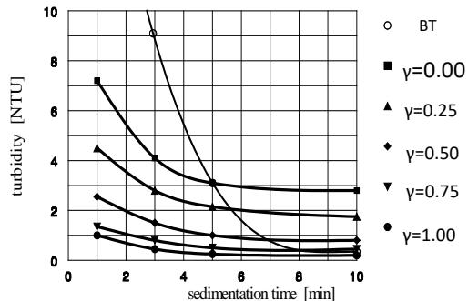 Figure 4: Significance of the
$\gamma$ -value reached prior to polymer addition on the kinetics of sedimentation of formed agglomerates and residual turbidity of the purified settled water
$$
\left(\mathrm {F e C l} _ {3}, \bar {G} = 7 8 \mathrm {s} ^ {- 1}, \mathrm {S F - A 1 1 0 , D _ {O A A}} = 0. 1 0 \mathrm {m g . L} ^ {- 1}\right)
$$
A similar situation exists regarding the settled water turbidity. The readings after 10 min. sedimentation showed that the lowest residual turbidity produced was achieved by BT, which equals to $\gamma = 1$. It follows from Figure 4 that the higher the $\gamma$ -value at which the polymer is dosed the faster the settling agglomerates are formed, producing the lowest residual turbidity of the settled water. Differences in the residual turbidity readings taken at different $\gamma$ -values between 1 and 10 minute sedimentation compare as follows:
<table><tr><td>Degree of aggregation y</td><td>(-)</td><td>0</td><td>0.25</td><td>0.50</td><td>0.75</td><td>1.0</td></tr><tr><td>Differences in turbidity between 1 and 10 min. sedimentation</td><td>(NTU)</td><td>4.4</td><td>2.75</td><td>1.75</td><td>0.9</td><td>0.8</td></tr></table>
The significance of $\gamma$ -values at which the polymer is introduced into the aggregating water is also evident by comparing the differences in residual turbidity of the settled water measured after 10 min sedimentation with that of BT (Figure 4). These differences are the result of the polymer's adverse influence on aggregation efficiency. The differences read as follows:
<table><tr><td>Degree of aggregation y</td><td>(-)</td><td>0</td><td>0.25</td><td>0.50</td><td>0.75</td><td>1.0</td></tr><tr><td>Differences in total turbidity at 10 min. sedimentation in comparison to the blind test</td><td>(NTU)</td><td>2.6</td><td>1.4</td><td>0.6</td><td>0.2</td><td>0.0</td></tr></table>
The turbidity produced only by the residual nonseparable particles follows the same pattern of separable particles (Figure 5). The highest residual turbidity produced by all particles and the nonseparable particles remaining in the purified water exist when the polymer is applied as coagulation aid, $\gamma = 0$. The lowest residual turbidity is produced when the aggregation is completed, $\gamma = 1$, before the polymer addition. This means, the aggregation efficiency and the residual turbidity of purified water produced by both types of particles are not detrimentally affected only when the polymer is applied as an agglomeration agent. Hence, the current method for using these polymers as aggregation aids is unsuitable as it detrimentally affects the purified water quality.
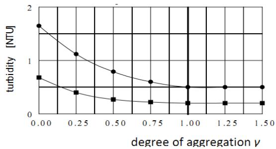 Figure 5: Influence of the
$\gamma$ -value on Residual Turbidity of the Purified Water and Produced by the Separable and non-Separable Particles
- total residual turbidity after 10 min sedimentation residual turbidity produced only by the nonseparable particles after 10 min sedimentation
$$
(\mathrm{FeCl}_{3},\,\bar{G}=100\,\mathrm{s}^{-1},\,\text{SF-A110},\,D=0.10\,\mathrm{mg}\cdot\mathrm{L}^{-1})
$$
The reasons for the poorer quality of the purified water when an anionic, or non-ionic polymer is applied as aggregation aid, $\gamma < 1$, can be explained by:
a. Interference of the polymers with the destabilization of the particles of impurities that leaves a greater quantity of the non-destabilized, non-separable particles in the purified water,
b. Re-stabilization caused by the polymers of some of the particles of impurities already destabilized but not yet aggregated.
b) Influence of the degree of aggregation $\gamma$ and polymer dosage on the quality of purified water
Jar tests were also carried out to establish the effect of different polymer dosages on the quality of purified water. The typical pattern of total residual turbidity of the purified water is illustrated in Figure 6. Again, it transpires from this Figure that the lower the $\gamma$ -values at which the polymer is applied and the higher the polymer dosage is applied, the poorer the purified water quality becomes. With increasing $\gamma$ -value, irrespective of the polymer dosing rate, the quality of purified water becomes better, and the differences disappear at $\gamma = 1$.
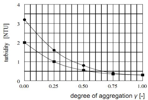 Figure 6: Influence of polymer dosages and
$\gamma$ -values reached prior to polymer addition on total turbidity of the purified water after 10 min. sedimentation
SF-A110 dosage: $0.10\mathrm{mg.L^{-1}}$ 0.05 ma.L-1 $\mathrm{FeCl}_3$ $\overline{G} = 50\mathrm{s}^{-1}$ SF-A110)
### c) Post-Orthokinetic Agglomeration
It is evident from Figures 4 to 6, the anionic and non-ionic polymer, when applied as an aggregation aid, reduces the aggregation capability of the aggregation agent. This detrimental effect is the greatest when the polymer is applied together or shortly after the aggregation agent and decreases as aggregation progresses before polymer addition.
Figures 4 to 6 also show that the best-purified water quality is always produced when the anionic and non-ionic polymers are applied at $\gamma = 1$. This proves that these polymers function as an agglomeration agent (OAA) and not as an aggregation aid as commonly practiced. Therefore, the best results are achieved when aggregation is already completed, $\gamma = 1$, prior to polymer addition. This method is called the Post-Orthokinetic Agglomeration (POA) process [1].
It was observed that the POA also improves the strength and resistance to fragmentation of the agglomerates formed.
### d) Effect of OAA dosage on the sedimentation kinetics of agglomerates
The effect of different OAA dosing rates on the sedimentation kinetics of agglomerates is illustrated in Figure 7.
Figure 7a shows how the POA process increases the size of the agglomerates and their sedimentation velocity with an increasing OAA dosing rate. The OAA dosing rate $D_{\mathrm{OAA}}$ varied between 0.01 and $0.1 \, \mathrm{mg.L}^{-1}$. At a dosage $D_{\mathrm{OAA}} \geq 0.03 \, \mathrm{mg.L}^{-1}$ the agglomerates were already so large that they began to settle during the agglomeration agitation; the higher the OAA dosage the larger and the more rapidly settling agglomerates were formed. It follows from this Figure that the dosing rate of OAA determines the sedimentation velocity of the agglomerates formed.
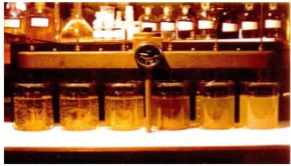
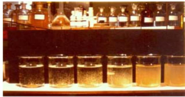
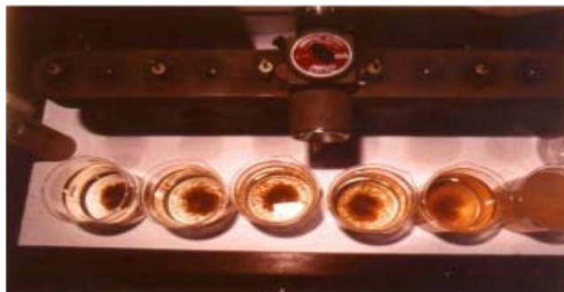 Figure 7: The effect of OAA dosing rate on settleability of agglomerates from right to left: NIL, 0.01; 0.03; 0.05; 0.07; 0.10 mg.L-1 (TuRW = 140 NTU,
$\gamma \approx 1$, = 78 s-1, aggregation agent: Floccotan, OAA: SF-A130)
- (a) Development of agglomerates during the POA process,
- (b) Sedimentation kinetic immediately after removal of stirrers,
- (c) The character of sediments produced
Figure 7b shows the effect of different OAA dosages on settleability of agglomerates immediately after the flocculator was switched-off and the stirrers removed from the beakers.
- Figure 7c shows the effect of different OAA dosages on the character of sludge produced; the consistency of sludge increases with increasing OAA dosage.
e) Significance of Electrolyte Ph on the Agglomeration Capability of OAA
Different OAA were dissolved in electrolytes of different pH to investigate the effect of pH on their agglomeration capability.
Anionic and non-ionic polymers were dissolved over a wide pH range in alkaline and acidic electrolytes. The effect of the different electrolyte pH values on the dissolution of these polymers at a concentration $C = 150 \, \text{mg.L}^{-1}$ was investigated by comparing pH values measured in both the electrolyte and the solution.
<table><tr><td>pH of electrolyte</td><td>2,8</td><td>4,8</td><td>9,0</td><td>11,0</td><td>12,4</td></tr><tr><td>pH of SF-905s solution</td><td>3,0</td><td>6,3</td><td>7,5</td><td>8,2</td><td>11,8</td></tr></table>
The difference between the two readings corresponds to the absorption of single ions from the electrolyte into the polymer macroions. In other words, these differences show the extent to which the electrolyte becomes a donor to the charged groups of the counter ions. This absorption contributes to development of a rodlike configuration of the polyvalent macroions, i.e. the enhancement of the agglomeration potential of OAA.
Similar results were also obtained with the anionic polymers.
### f) Effect of the Electrolyte pH on the OAA Solution
During the dissolution of different OAA it was found that their solubility was to a great extent dependent on the electrolyte pH and the brand of OAA (anionic or non-ionic).
Solubility of the anionic polymers increased with an increasing alkaline pH over the full range of pH tested. It was observed that a homogeneous solution free of "fish eyes" was only obtained at a pH > 10; the solution is not homogeneous in the range of pH = 7 to 10. "Fish eye" clusters could not dissolve even after prolonged mixing. The quantity of "fish eye" clusters decreased as the pH increased, and only at a pH > 10 they completely disappeared. For example, the dissolution of SF-A110 at a concentration of C = 150 mg.L $^{-1}$ in a 0.025 N NaOH electrolyte (pH ≈ 11) to a homogeneous solution free of "fish eyes" was completed in about 4 hours. In an acidic range between a pH = 7 to 4, solubility is so low that the anionic polymers could not dissolve into a homogeneous solution not even during 10 hours dissolving.
Generally, the time required for dissolution of any OAA increases with increasing solution concentration.
All polymers must be dissolved to a clear and homogeneous solution to prevent reduction in their agglomeration capability. For this reason the clarity of electrolyte is very important. The water used for the electrolyte must be soft, or softened to prevent the formation of a precipitate after its alkalization before polymer dissolution. In the event of a precipitate being formed, the agglomeration capability of the polymer solution is considerably reduced.
### g) Effect of the Electrolyte pH on the Chemical Structure of OAA
During dissolution the OAA produces either non-ionised molecules or clusters of molecules, or dissociates into polyvalent macroions, polyions, and a great number of single ions of opposite charge, the counter ions. The counter ions of the same charge distributed along the macroion repel each other and this results in the stretching of the fibrous molecule. The macro-molecules in their elongated, rodlike configuration have the greatest agglomeration efficiency while the coil-like macro-molecules have the lowest efficiency. The degree of dissociation, and the stretching of the macro-molecules, is influenced by the electrolyte pH and the concentration of the OAA solution.
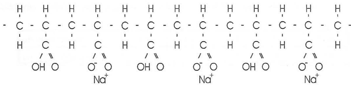
The effect of the electrolyte pH on the chemical structure of the macromolecule of polyacrylic acid is explained by Oosawa [28] as follows. With polyacrylic acid the degree of dissociation of the carboxyl group is small in pure water. By adding an alkali (NaOH) the number of negative charges producing $\mathrm{Na^{+}}$ counter ions increases. The quantity of the added alkali is reflected in the pH value of the solution. Likewise, the chemical structure of the macroions in the solution may be expressed as a copolymer of monomers having $\mathrm{COOH^{-}}$ and $\mathrm{COO^{-}}$ groups. At a given pH value and concentration of macroions, the pH value indicates the average proportion of these groups because the solution is a mixture of macroions that have noticeable distributions of two thermally fluctuating groups. When alkali is added on an equimolar basis to the acidic groups, the sodium polyacrylate macroions in the resulting solution are almost entirely dissociated.
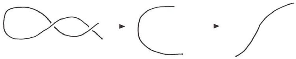
The strong charge of the macroions produces a strong electric field, which attracts the counter ions. The charged macroions can assume various random coil configurations over a wide range of extensions, which are dependent on the charge of the environment. In an environment they may take on a rodlike or cylindrical configuration. At low charge densities or in the absence of a charge, the coil configuration can take on a coil-like or spherical configuration. The spherical random coil can have a wide range of apparent radii. For example, the polyacrylic acid whose degree of polymerization is 1000, takes on a spherical random coil form with a radius of about $200\mathring{\mathrm{A}}$ at a low pH. With an increasing pH the macroion extends first spherically and then becomes rodlike, and its resultant length is 2500 Å in its most elongated form. The average local curvature of the chain decreases gradually, as shown below:
### h) Effect of the Electrolyte pH on the Viscosity of OAA Solutions
The anionic SF-A110 and non-ionic SF-905s were dissolved at a concentration $C = 150 \, \mathrm{mg.L}^{-1}$ in electrolytes of pH varying between 3 and 12. The viscosities of these solutions are plotted in Figure 8.
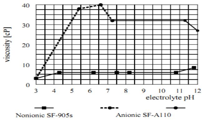 Figure 8: The effect of electrolyte pH on the OAA solution viscosity
- The anionic SF-A110 could not be dissolved in the acidic pH range and, therefore, its viscosity is shown by a dashed line. In the alkaline pH range, the viscosity remained stable up to a pH around 11 and decreased slightly at a pH > 11.3. In contrast to that, the viscosity of the non-ionic SF-905s solution remained very steady between pH = 4.3 and 10.8. At a pH > 11 it increased slightly, and at a pH < 4.3 it decreased slightly. The viscosity measurements were repeated several times. The measured viscosities varied slightly in the absolute values, however the pattern remained the same.
i) The Effect of pH of OAA Solutions on their Agglomeration Potential
The influence of the solution pH value for enhancing agglomeration capability of both anionic and non-ionic OAA is evident from the comparison of the sedimentation kinetics in Figures 9 and 10. Figure 9 illustrates the effect of the solution pH of anionic SA-A110, and Figure 10 of the non-ionic SF-905s. The lowest agglomeration capability of the anionic OAA, characterized by the highest residual turbidity (the lowest sedimentation velocity), is reached at pH = 3.2
(Figure 9). At this low pH the configuration of polymer molecules corresponds to their most coil-like spherical configuration. The agglomeration capability gradually improves over the full range of pH tested. The highest agglomeration capability exists at the lowest turbidity (the highest sedimentation velocity) and the highest pH = 12. At this high pH the configuration of polymer molecules corresponds to its most stretched rod-like configuration.
The lowest agglomeration capability of the nonionic OAA, characterized by the highest residual turbidity (the lowest sedimentation velocity), is reached at around neutral pH = 7 (Figure 10). At this pH the configuration of polymer molecules corresponds to their most coil-like spherical configuration. The agglomeration capability gradually improves in both directions up to the highest pH = 11.5 and the lowest pH = 3.0. The polymer molecules configuration corresponds to their most stretched rod-like configuration at the highest and lowest pH values.
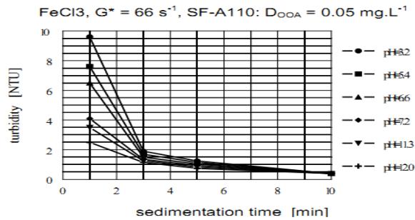 Figure 9: The effect of pH of the anionic OAA solution on the sedimentation kinetics of agglomerates
### j) Effect of the Concentration of OAA Stock Solution on the Sedimentation Kinetics
The concentration of the polymer stock solution is also an important factor influencing the agglomeration capability of OAA. The effect of the concentration of OAA stock solution on its agglomeration capability was investigated with the concentrations of $150\mathrm{mg}$. $\mathsf{L}^{-1}$ and $1500\mathrm{mg.L}^{-1}$; the stock solution matured for 24 hours. The results obtained with SF-A110 are shown in Figure 11 and can be considered typical for any OAA. These results show that agglomeration capability decreases with increasing concentration of stock solution.
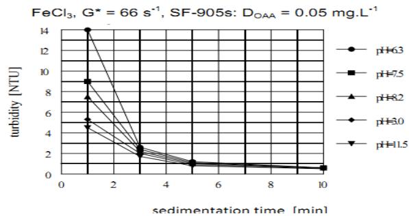 Figure 10: The effect of pH of the non-ionic OAA solution on the sedimentation kinetics of agglomerates
Figure 11 also shows how the inline dilution of the concentrated stock solution is very ineffective. This can be explained as follows: Inline dilution of the concentrated stock solution cannot produce a homogenous solution within the short time available during inline dilution. The diluted solution contains droplets of the concentrated stock solution and the dilution water. Such diluted solution tends to retain the agglomeration efficiency close to the concentration of stock solution. To achieve the same agglomeration efficiency as that attainable with the stock solution of low concentration, a greater OAA dosage is required.
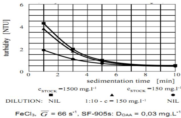 Figure 11: The effect of inline dilution of the OAA solution on the kinetics of sedimentation of agglomerates
The use of a high concentration stock solution is very inefficient and uneconomical and, therefore, cannot be recommended. As evident from the above, the stock solution should be prepared at a concentration at which it will be applied to the purification process, preferably not exceeding $1.0\mathrm{g.L}^{-1}$.
### k) Effect of the Maturation Time of OAA Solution
The effect of maturation (aging) time of OAA solution is yet another factor that was investigated to discover whether it had any effect on the agglomeration efficiency. In this regard, similar results were obtained with both the anionic and non-ionic OAA. The results plotted in Figure 12 were obtained with three SF-A130 solutions of the same concentration but of three different maturation times; one is freshly prepared, the other is 24 hours old and the last one is 30 days old.
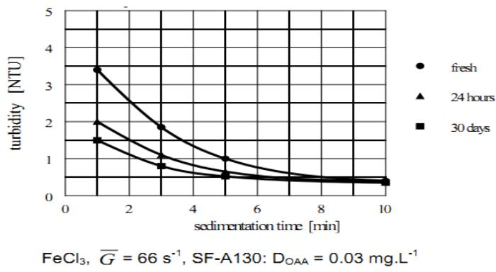 Figure 12: The effect of maturation time of the OAA solution on the sedimentation kinetics of agglomerates formed
The settling curves in Figure 12 show the fresh solution applied immediately after its preparation has the lowest agglomeration efficiency. A significant improvement is achieved when the solution matures for 24 hours before its usage. At a maturation longer than 24 hours the rate of efficiency increase slows down. Therefore, it is advisable to mature OAA solution preferably for 24 hours before its usage. In the event this is not possible then the solution should mature at least for 12 hours before its usage.
Furthermore, it was found that the viscosity of solutions slightly increased with maturation time.
### i) Significance of Homogenization of the OAA Solution with the Aggregated Water
Yet another factor affecting the agglomeration efficiency is the speed of the dispersal mixing required to achieve homogenization of the dosed OAA solution with the aggregated water. Such dispersion should be completed as fast as possible to ensure that all aggregates are individually exposed to OAA to achieve the highest agglomeration efficiency.
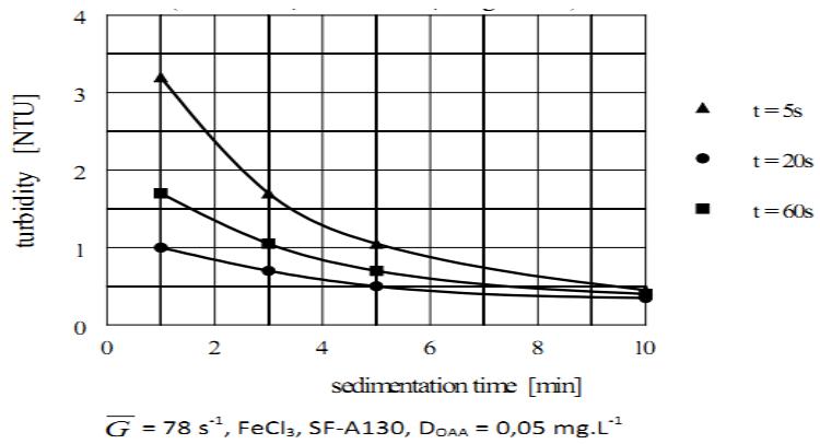 Figure 13: The effect of dispersion mixing time of the OAA solution on sedimentation kinetics of agglomerates
The typical effect of different times of dispersal mixing on the agglomeration efficiency is shown in Figure 13. It follows from this Figure, the sedimentation kinetics of the formed agglomerates improves until the homogenization of OAA solution with the aggregated water is completed. It also shows that the optimum dispersal mixing time peaked at about 20 s as the most rapidly settling agglomerates were formed. Furthermore, it follows from Figure 13 the dispersal mixing lasting longer than the optimum time is less harmful to the efficiency of the POA process than is a shorter time at which homogenization is not yet completed.
It was also established, although the results are not shown, that the time required to complete homogenization depends not only on the intensity of dispersal mixing but also on the concentration of the dosed solution. A longer time is needed for the solution of higher concentration.
### j) Comparison of the Agglomeration Efficiency of Different Kinds of OAA
The agglomeration capability of different anionic and non-ionic OAA is compared in Figures 14 and 15.
Figure 14 compares the sedimentation kinetics of different anionic OAA and Figure 15 different nonionic OAA. The dosage of all OAA was the same, $D = 0.03 \, \mathrm{mg.L}^{-1}$. The most efficient anionic OAA are SF-A110 and SF-A130 and non-ionic OAA is SF-905s, all provided by Cyanamid Co. of USA. The LT-26 provided by the Allied Colloids of UK was found to equal the Superflocs
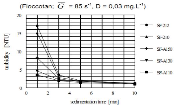
Figure 14: Comparison of sedimentation kinetics of different anionic OAA
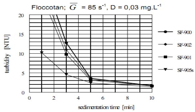 Figure 15: Comparison of sedimentation kinetics of different non-ionic OAA
### k) High Rate Clarification Technology
Innovations emanating from this project resulted in the development of the High Rate Clarification Technology (HRCT) (Figure 16).
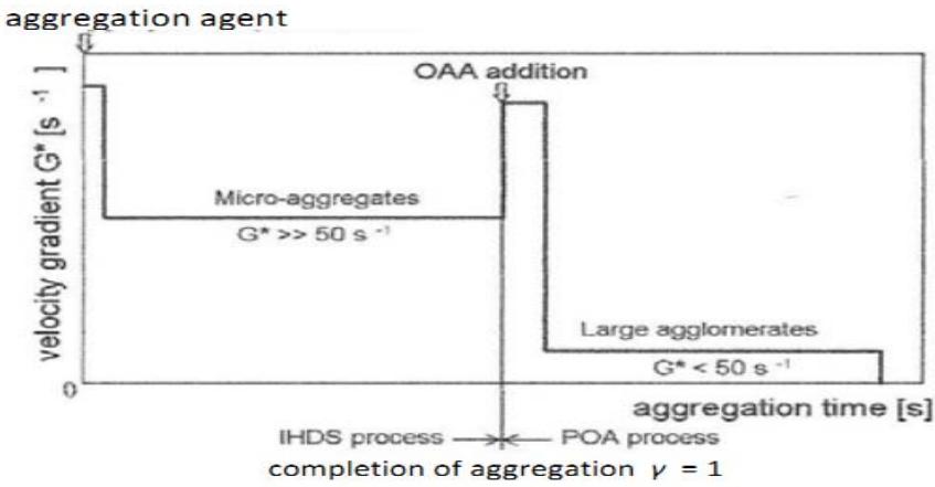 Figure 16: Formation of agglomerates by High Rate Clarification Technology incorporating the IHDS and POA processes
$(G^{*} =)$
The HRCT combines two processes developed for this purpose, namely:
- (a) The Inline High Density Suspension formation process producing dense micro-aggregates,
- (b) The Post-Orthokinetic Agglomeration process agglomerating these micro-aggregates to large rapidly settling agglomerates by means of OAA.
The feasibility of all these innovations was verified under long operation of the pilot HR clarifiers and subsequently under the operation of a large capacity plant. The results achieved are presented in the following Chapter.
## VI. DESIGN, OPERATION AND PERFORMANCE RESULTS OF HIGH RATE CLARIFIERS
### a) High Rate Clarifiers
Two types of clarifiers, the High Rate clarifiers incorporating the principles of the HRCT, were developed, namely:
- (a) HR clarifier (Figure 17) is a vertical flow type fully fluidized sludge blanket clarifier; this clarifier is particularly suitable for continuous operation under both a steady flowrate, and a relatively slow and gradual fluctuation of the raw water quality,
- (b) P-Clarifier (Figure 18) is a radial flow type clarifier with the removal of settled sludge by hydraulic means; this clarifier is suitable for intermittent operation; the formation of micro-aggregates is carried out to completion in a Flocculator installed next to the P-Clarifier.
Three types of suspension can be handled by the High Rate Clarifiers, namely:
- (a) the conventionally formed flocculant suspension,
- (b) the micro-aggregates formed by aggregation under the IHDS process,
- (c) solid particles up to the finest size contained in the surface water and underground mine water.
## i. HR Clarifier
The best hydraulically balanced clarifier, the CSAV type [30], incorporating flocculation, a fully fluidized sludge blanket, clarified water and sludge thickening compartments, was converted to the HR Clarifier (Figure 17).
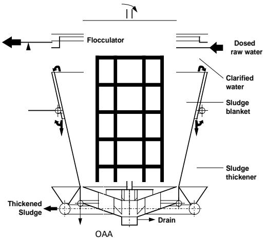 Figure 17: The HR Clarifier
From a process point of view, this conversion includes:
a) Uprating of the aggregation process from taking place under conventional low intensity agitation to the IHDS process taking place at high intensity agitation and completing aggregation ( $\gamma = 1$ ) within the Flocculator and completing it in the Flocculator,
b) Changing the sludge blanket function from continuation of aggregation to the POA process where the micro-aggregates formed in the Flocculator are agglomerated to large, rapidly settling agglomerates by means of OAA (organic agglomeration agent); the OAA are anionic or nonionic water-soluble polymers.
Conversion of the CSAV clarifier arrangement involved modification of the Flocculator to incorporate:
a) Installation of a double-frame, double-anchor, n-tier type stirrer driven by a variable speed drive,
b) Installation of OAA dosing points above the Flocculator bottom and
c) Installation at the Flocculator bottom of a system of deflector baffles to neutralize the rotary motion of the water before entering the sludge blanket compartment.
Raw water containing dispersed coagulant (aggregation agent) discharged from a flash mixer enters the Flocculator. In this compartment, the aggregation takes place under the IHDS process at a high agitation intensity ( $\overline{G} >> 50 \, \text{s}^{-1}$ ); the aggregation is completed ( $\gamma = 1$ ) within the Flocculator. The OAA solution is dosed into the Flocculator bottom above the deflector baffles to facilitate its homogenization throughout the aggregated water within the Flocculator before entering the sludge blanket. The deflector baffles neutralize the effect of the rotary motion of water before entering the sludge blanket compartment. The attainable up flow velocity in the sludge blanket, at which the agglomerates are separated, can be varied over a wide range by changing the OAA dosing rate. This is because OAA dosage influences the size of agglomerates formed and their attainable sedimentation velocity. The aggregated water with evenly dispersed OAA enters the conically shaped sludge blanket compartment via an inlet slot. Here, under a low agitation intensity ( $\overline{G} << 50 \, \text{s}^{-1}$ ), produced by the turbulent fluctuations of the inflowing water, the micro-aggregates are agglomerated to large and rapidly settling agglomerates. No agglomerates are allowed to settle and deposit at the bottom of the sludge blanket compartment as this would facilitate disturbance of the hydraulic balance throughout the sludge blanket compartment and detrimentally affect the clarifier performance. The formed agglomerates are separated from the purified water at the sludge blanket level by continuously draining-off the excess suspension from the sludge blanket level by means of the induced flow into the sludge compartment. In this compartment the suspension settles and thickens by way of compression. The flow of decanted water from the sludge compartment is combined with the main outlet of purified water discharged from the clarifier. The accumulated sludge is periodically drained-off through the perforated pipe. The sludge compartment is provided with a few sampling pipes to monitor the sludge level and its concentration at different levels. The purified water discharged from the sludge blanket flows through the purified water compartment, where it is evenly collected over the compartment level and discharged from the clarifier at its outlet.
## ii. $P$ -Clarifier
The P-Clarifier (Figure 18) is a circular, horizontal flow, sedimentation type clarifier, suitable for intermittent operation. It incorporates aggregation, sedimentation, purified water and sludge accumulation/thickening compartments. When used as a high rate type, the aggregation takes place to completion in a separate Flocculator installed next to the clarifier. When used for dewatering of thin sludge, the function of the
Flocculator changes to the POA process. The sludge compartment is designed to deposit and thicken the settled sludge by compression and to prevent a back-lifting of sludge into the sedimentation compartment during desludging. The sludge is periodically drained-off by hydraulic means through a perforated pipe.
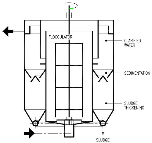 Figure 18: P-clarifier
### b) Methods and Procedures
The performance efficiency of the clarifiers was evaluated by changes in the content of the cation (Me) of the $\mathrm{Fe}^{3+}$ or $\mathrm{Al}^{3+}$ salt, when a hydrolyzing type of aggregation agent was used. Furthermore, changes in natural organic matter (NOM) were measured as $\mathrm{COD}_{\mathrm{Mn}}$, TOC or DOC in both the raw water and the settled water, irrespective of the kind of aggregation agent used.
The total concentration of the specific impurity measured in the raw water is designated by $C_0$, and $C_0F$, at the clarifier outlet by $C_C$ and $C_C F$, and in the filtrate by $C_F$ and $C_F F$. The quantities $C_0$, $C_C$ and $C_F$ mean total concentration of the particular impurity produced by all particles. Abridger $F$ means the content of such impurity is produced only by the non-separable particles. The concentration of non-separable particles $C_0F$, $C_C F$ and $C_F F$ was determined in the tested samples from which the separable particles were removed under specific conditions of centrifugation [8-10].
Turbidity produced by the total content of all particles and the content of non-separable particles was measured by a Hach turbidity meter model 2100A. The concentration of the cation of the aggregation agent was measured colorimetrically by a Bausch & Lomb Spectronic model 70.
The NOM was measured colorimetrically as $\mathrm{Com}_{\mathrm{den}}$ (oxidizability) by oxidation of the organic matter in a boiling mixture of potassium permanganate $(\mathrm{KMnO}_4)$ and sulphuric acid.
The size distribution of formed aggregates was determined by the Test of Aggregation using a Labofuge 1 laboratory centrifuge. The Test of Aggregation ascribes the aggregates formed to one of the following four basic technological size-fractions, namely: non-aggregated (non-separable) particles (NA), primary aggregates (PR), micro-aggregates (MI) and macro-aggregates (MA). Coagulation efficiency was evaluated by the degree of destabilization $\delta$. The concentration of any type of the monitored impurity is measured by the total concentration of all particles $C$ and by concentration of its non-separable fraction $CF$. The removal of individual impurities was evaluated by the attained $\varphi$ and attainable $\varphi$ separation efficiency [1, 8-10].
The degree of destabilization is the basic criterion of destabilization of the particles of impurities. It is defined as the ratio of the number of particles destabilized in the course of aggregation $N_{D}$ to the number of aggregately-stable (non-separable) particles in the raw water $N_{NS}$ [8-10].
The aggregation agents, namely ferric chloride and aluminium sulphate (hydrolyzing coagulants) and Floccotan and SF-577 (organic coagulants), were used. These organic coagulants are described under Aggregation Agents.
The OAA used are polyacrylamides, mainly Superflocs SF-110 and SF-A130, provided by the Cyanamid Co. of USA.
## i. Raw Water
The HR clarifiers purified water from three different surface sources. The raw water quality in these sources is summarized in Table 1.


Table 1: Average quality of different raw waters purified by the pilot HR clarifiers
<table><tr><td>DETERMINANT</td><td>UNITS</td><td>VAAL DAM</td><td>LOCH ATHLONE DAM</td><td>SAULSPOORT DAM</td></tr><tr><td>Temperature</td><td>°C</td><td>10 - 26</td><td>12-25</td><td>12 – 25</td></tr><tr><td>pH</td><td>-</td><td>6.9 – 8.5</td><td>7.7</td><td>7.4 – 8.2</td></tr><tr><td>Turbidity</td><td>NTU</td><td>150 - 200</td><td>50 - 690</td><td>30 – 250</td></tr><tr><td>Color</td><td>mg Pt. L-1</td><td></td><td>5 – 15</td><td>10 – 40</td></tr><tr><td>Total Hardness</td><td>mg CaCO3, L-1</td><td>37 - 105</td><td>108</td><td>90 – 160</td></tr><tr><td>Total alkalinity</td><td>mg CaCO3, L-1</td><td>42 – 110</td><td>75</td><td>75 – 150</td></tr><tr><td>CODMn</td><td>mg O2. L-1</td><td>4.0</td><td>3.4</td><td>5.8 – 6.5</td></tr><tr><td>THM – potential value</td><td>μg CHCl3, L-1</td><td>-</td><td>-</td><td>878</td></tr></table>
## ii. Velocity Gradient
The mean square root velocity gradient $\overline{G}$ is a parameter ascertaining the average intensity of agitation applied to aggregation. From an operational point of view it is important to evenly distribute the intensity of agitation throughout the Flocculator and to best utilize the retention time in the Flocculator by preventing short circuiting. Hence, great attention has been given to developing a stirrer facilitating these requirements. Such stirrer, a double-frame, double-anchor, n-tier type generating flow in a plane perpendicular to the stirrer shaft, was developed. This stirrer is driven by a variable speed drive thus ensuring the intensity of agitation required to complete aggregation within the Flocculator can be maintained at all times.
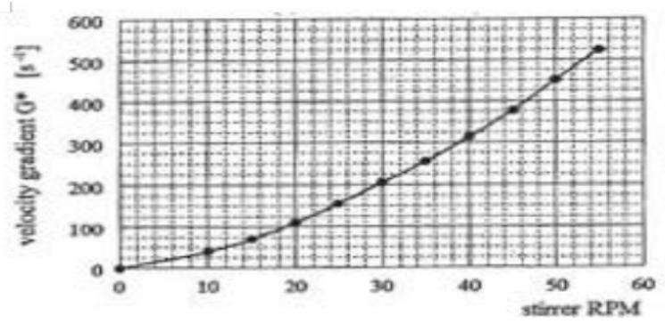 Figure 19: 3 m HR Clarifier - Conversion of Stirrer RPM to Mean Square Root Velocity Gradient
$G^* =$
The power input, shaft-to-water, was determined from the energy consumed by the stirrer revolving at different revolutions in the Flocculator filled with water, and then again, at the same revolutions when it is empty. The difference between these two power readings is the actual power input, shaft-to-water, dissipated by the stirrer into the water under operating revolutions. From these power inputs, the mean square root velocity gradients $\overline{G}$ were calculated. Conversion of the stirrer speed to the velocity gradient $\overline{G}$ is shown in Figure 19.
## iii. Concentration of Drained Sludge
The concentration of sludge discharged from the clarifiers was determined as an average concentration established from samples taken either from sludge discharged at the beginning, middle and at the end of desludging, or directly from the samples taken from the sludge compartment at different heights.
Sludge concentrations varied depending on the retention time in the sludge compartment.
## VII. RESULTS AND DISCUSSION
### a) Pilot Hr Clarifiers
Two $3.0\mathrm{m}$ diameter pilot HR clarifiers were installed at two different localities to demonstrate the potential of the HRCT and to eliminate any doubts about the feasibility of this progressive technology.
The design parameters of the pilot HR clarifiers are as follows [1]:
- > Clarifier diameter
- > Overall height of the clarifier
- > Clarifier volume
- $\succ$ Design capacity (flow rate)
- > Agitation intensity during IHDS aggregation process
- > Area of the sludge blanket at its separation level
- $\succ$ Design upflow velocity at the sludge blanket level
- > Area of separation level in the sludge compartment
- Retention time in the clarifier at the design flow
b) Installation, Operation and Performance of the First Pilot HR Clarifier
The first pilot HR clarifier was installed at the Rand Water Board Zuikerbosch Waterworks (Figure 20) and operated for about one year during 1970 to 1971. Vaal Dam water was purified (Table 1). Either aluminium sulphate or Floccotan was used as the aggregation
$D_{C}$ $= 3000\mathrm{mm},$
$H_{C}$ $= 4.0\mathrm{m}$
$V_{C}$ $= 24\mathrm{m}^{3},$
Q 21.15 m3.h-1
$$
= 5 0 7. 6 0 \mathrm {m} ^ {3}. \mathrm {d} ^ {- 1}
$$
$\overline{G}$ $= 100 - 400\mathrm{s}^{-1}$
$F_{SB}$ $= 4.7\mathrm{m}^2$
$V_{UP}$ $= 4.5\mathrm{m.h}^{-1},$
$F_{ST}$ $= 3.0\mathrm{m}^2$
$T_{\mathrm{C}}$ 68min.
agent. The OAA used was SF-A110. It was dissolved at a concentration of $1.0\mathrm{g.L}^{-1}$ in 0.025 N NaOH electrolyte prepared from distilled water.
The clarifier performance results were remarkable even though its full potential could not be established due to the low flow rate of the raw water delivery pump.
The clarifier operation and performance capability is summarized as follows [1]:
- $\succ$ Flowrate - limited by the raw water pump capacity
- > Upflow velocity at the sludge blanket level:
- > Total retention time in the clarifier at the maximum flow
- $\succ$ Raw water turbidity:
- $\succ$ Residual turbidity at the clarifier outlet:
$Q = 500$ to $1150\mathrm{m}^3.\mathrm{d}^{-1}$
$v_{UP} = 4.5$ to $10.2\mathrm{m.h^{-1}}$
$T_{C} = 30\mathrm{min},$
$C_0 = 150$ to 200 NTU
$C_{\mathrm{C}} = 1$ to 5 NTU
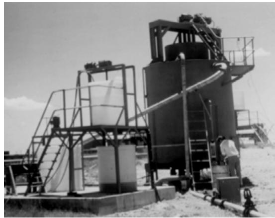 Figure 20: Installation of the pilot HR clarifier at the RWB Zuikerbosch waterworks
c) Installation, Operation and Performance Results of the Second Pilot HR Clarifier
The second pilot HR clarifier (Figure 21) was installed at the municipal waterworks of the City of Bethlehem, Orange Free State, purifying water from the Loch Dam or Saulspoort Dam or a mixture of both (Table 1). This clarifier was operated for seven years during the period of 1974 to 1980 by the waterworks staff. The purified water (on average higher than about $1500\mathrm{m}^3.\mathrm{d}^{-1}$ ) was used to supplement the shortfall in the waterworks capacity.
Aluminium sulphate alternating with Floccotan or Superfloc SF-577 were used as Aggregation agents. SF-A110 was solely used as the OAA; it was dissolved at a concentration of $1.0\mathrm{g.L}^{-1}$ in plain tap water because distilled water could not be secured at the daily quantities required. Another OAA, the Allied Colloids LT-25, was also successfully tested, even though for a very short time only. The performance efficiency of both OAA was very similar.
In conformity with the requirements of SABS 241 and common practice in South Africa, the clarifier's performance was monitored by residual turbidity only. Other determinants, such as the residual concentration of the cation (Me) of the aggregation agent used, and NOM (TOC, DOC, $\mathrm{COD}_{\mathrm{Mn}}$ ) could not be routinely monitored because the waterworks laboratory was not equipped for such analysis.
The raw water to the HR clarifier was delivered by gravity; it was branched off from the delivery pipeline to the waterworks. Depending on the volume of the purified water in the reservoirs, the throughput of the waterworks regularly changed. This often happened during the night hours. As a result, the HR clarifier throughput often changed without warning and consequently without adjustment of the dosing rates and, or intensity of agitation in the Flocculator. Higher residual turbidity in the clarifier outlet is usually a direct consequence of such a situation. Under the optimized operational conditions the residual turbidity at the clarifier outlet did not exceed 5 NTU even at the clarifier's highest upflow velocities. The higher residual turbidity resulted from $\gamma < 1$ and, or sub-dosages of aggregation agent (producing a poorer quality of purified water) or OAA (resulting in a greater remaining concentration of suspension in the clarifier outlet).
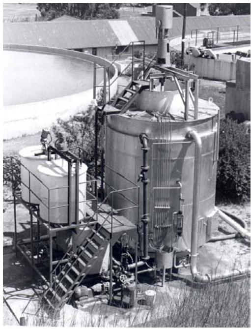 Figure 21: Installation of the second pilot HR clarifier at the municipal waterworks of the City of Bethlehem
This HR clarifier performed as follows [1, 31]:
- > Flowrate:
- > Upflow velocity at the sludge blanket level:
- Retention time in the clarifier:
- > Clarifier outlet turbidity:
- IHDS process
- Volume of drained sludge:
- The highest concentration of SS in drained sludge
The maximum hydraulic loading $Q = 120 \, \text{m}^3 \cdot \text{h}^{-1}$, corresponding to an upflow velocity $v_{SB} = 25.5 \, \text{m} \cdot \text{h}^{-1}$, which occurred accidentally, as the pressure in the feed pipe to the HR Clarifier increased, due to reduced flow to the waterworks. Under this flowrate the HR clarifier operated as follows: $C_0 = 108 \, \text{NTU}$, $C_O F = 58 \, \text{NTU}$, $D_{OC} = 5.94 \, \text{mg} \cdot \text{L}^{-1}$, $D_{OAA} = 0.126 \, \text{mg SF-A110} \cdot \text{L}^{-1}$, $\gamma \approx 0.22$, $C_C \leq 21 \, \text{NTU}$, $C_C F \leq 5.2 \, \text{NTU}$. The high residual turbidity is the consequence of the system being underdosed, both with the aggregation agent and SF-A110 and being extremely under-aggregated as $\gamma \approx 0.22$. After the agitation intensity and dosages of the aggregation agent and OAA were optimized the performance efficiency improved and returned to its usual level of $C_C < 5 \, \text{NTU}$. The total retention time in the
$$
\begin{array}{l} Q = 5 0 0 - 2 8 7 7 \mathrm {m} ^ {3}. \mathrm {d} ^ {- 1}, \\\begin{array}{r l r} {\mathsf {v} _ {U P}} & = & {4. 5 - 2 5. 5 \mathsf {m . h} ^ {- 1},} \end{array} \\T _ {c} = 6 8 - 1 2 \mathrm {m i n s}, \\C c = 2 - 9 N T U, \\\bar {G} = 1 0 0 - 3 8 0 \mathrm {s} ^ {- 1}, \\V_{S} = 0.245\% Q, \\C _ {S} = 73.05 \quad \mathrm{g}. \mathrm{L} ^ {- 1} \quad (7.305 \%). \\\end{array}
$$
clarifier between the point of addition of the aggregation agent and the clarifier outlet was only $T_{c} = 11.9 \mathrm{~min}$.
### d) Comparison of Performance of the HR Clarifier with Conventional Clarifiers
The pilot HR clarifier was operated in parallel with three Clariflocculators (2 x D = 10.5 m and 1 x D = 14.0 m) and a Pretreator clarifier (D = 18.5 m). The Clariflocculator is a radial flow type sedimentation clarifier with the flocculation compartment sized for about 20 min retention time and a very low intensity mechanical agitation. The Pretreator is a radial flow type sludge blanket clarifier with continuously forced internal sludge recirculation to keep the sludge blanket fluidized.
When comparing performance efficiency, these clarifier systems were operated under the following conditions to produce the same total residual turbidity of the purified water:
- The Clariflocculator (dia $14.0\mathrm{m}$ ) - operated at the design and sedimentation velocity $v_{s} = 1.2\mathrm{m.h}^{-1}$ and retention time of about $T_{c} = 4$ hours.
- The Pretreator - operated at the design upflow velocity $v_{UP} = 1.5 \, \text{m.h}^{-1}$ and retention time of about $T_{C} = 3.5$ hours.
- The HR clarifier - operated at an upflow velocity $v_{UP} = 15.5 \, \text{m.h}^{-1}$ and retention time of about $T_{C} = 20$ minutes.
The Clariflocculators and the Pretreator were supplied with water pre-aggregated in a shared hydraulically operated flocculation basin, where aggregation took place under the regular low intensity agitation and a retention time of about 20 mins. The discharge from this basin to the Pretreator was over a hydraulic jump (height of about $600~\mathrm{mm}$ ). In the case of the HR clarifier the aggregation agent was dosed into an inline flash mixer installed upstream of the clarifier Flocculator. The IHDS process in the HR clarifier took place with $\overline{G} = 330\mathrm{s}^{-1}$.
The waters purified by the HR clarifier and the Clariflocculators were combined and filtered together while the water purified by the Pretreator was filtered in a dedicated filtration plant.
The aluminium sulphate dosage, purifying water to the same total residual turbidity in all three clarifiers, was about $13\%$ lower for the HR clarifier than that applied to the Clariflocculators and Pretreator (Table 2). This proves the importance of the rapid dispersion of the aggregation agent at the flash mixer together with the subsequent high intensity agitation during aggregation facilitating completion of destabilization of particles of impurities and their aggregation.
The performance of these three clarifier systems, evaluated by the Test of Aggregation, is compared in Table 2, and the distribution particle size-fractions is illustrated in Figure 22.
A drop in residual turbidity $C_{\mathrm{C}}F$ measured at the outlets of different sections of the clarifier system (Table 2) indicates the extent of the efficient improvement of the purification process. The HR clarifier produced the lowest turbidity $C_{\mathrm{C}}F = 1.4$ NTU, while the Pretreator was very close to it, $C_{\mathrm{C}}F = 1.5$ NTU. A considerably higher turbidity was produced by the Clariflocculator, $C_{\mathrm{C}}F = 2.9$ NTU. The relatively high $C_{\mathrm{C}}$ and $C_{\mathrm{C}}F$ values at the outlet from the HR clarifier are due to a $13\%$ lower dosage of the aggregation agent than the optimum applied to the other clarifiers. The low $C_{\mathrm{C}}F$ value of the Pretreator in comparison to the Clariflocculators was partly due to the hydraulic jump at the end of pre-aggregation enhancing destabilization of impurities and partly due to the enhancing effect of the sludge blanket. Undoubtedly, the highest $C_{\mathrm{C}}F$ value produced by the Clariflocculator proves that a low agitation intensity applied to the aggregation process does not favourably affect enhancement of the processes of destabilization of particles of impurities and their aggregation.
Table 2: Comparison of the performance efficiency of different clarifiers installed at the municipal waterworks of the City of Bethlehem, OFS [1, 31]
<table><tr><td>Source of raw water:</td><td>Mixture of Saulspoort Dam and Loch Athlone Dam waters</td></tr><tr><td rowspan="2">Raw water turbidity:</td><td>C0= 102 NTU</td></tr><tr><td>C0F = 54 NTU</td></tr><tr><td>Date of plant operation:</td><td>November 12, 1978</td></tr><tr><td>Aggregation agent:</td><td>Aluminium sulphate</td></tr><tr><td>Optimum dosage (Tu removal):</td><td>DAI= 60 mg.L-1</td></tr></table>
NA - non-separable (non-aggregated) particles
PR - primary-aggregates
MI - micro-aggregates
MA - macro-aggregates
<table><tr><td rowspan="2">TYPE OF CLARIFIER</td><td colspan="2">DOSING RATE</td><td rowspan="2">UPFLOW VELOCITY [m.h-1]</td><td rowspan="2">POINT OF MEARUREMEN TS</td><td colspan="2">TURBIDITY</td><td rowspan="2">DEGREE OF DESTABILISATIO N δ [-]</td></tr><tr><td>Aluminium sulphate [mg.L-1]</td><td>SF-A110 [mg.L-1]</td><td>Cc[NTU]</td><td>CcF[NTU]</td></tr><tr><td></td><td></td><td></td><td></td><td>Raw Water</td><td>102</td><td>54</td><td>-</td></tr><tr><td rowspan="2">Pretreator (Retention time about 3.5 hrs)</td><td rowspan="2">60</td><td rowspan="2">0</td><td rowspan="2">1.5</td><td>Pre-aggregation chamber outlet</td><td>102</td><td>4.9</td><td>0.909</td></tr><tr><td>Hydraulic jump</td><td>102</td><td>4.0</td><td>0.926</td></tr><tr><td></td><td></td><td></td><td></td><td>Clarifier outlet</td><td>7.1</td><td>1.5</td><td>0.972</td></tr><tr><td rowspan="2">Clariflocculator (Retention time about 4 hrs)</td><td rowspan="2">60</td><td rowspan="2">0</td><td rowspan="2">1.2</td><td>Pre-aggregation chamber outlet</td><td>102</td><td>4.9</td><td>0.909</td></tr><tr><td>Clarifier outlet</td><td>7.2</td><td>2.9</td><td>0.946</td></tr><tr><td rowspan="2">HR Clarifier (Retention time about 20 min)</td><td rowspan="2">52</td><td rowspan="2">0.172</td><td rowspan="2">15.5</td><td>Flocculator outlet</td><td>102</td><td>1.7</td><td>0.969</td></tr><tr><td>Clarifier outlet</td><td>7.0</td><td>1.4</td><td>0.974</td></tr></table>
SF-A110 was dissolved in tap water
<table><tr><td rowspan="2">TYPE OF CLARIFIER</td><td rowspan="2">POINT OF MEARUREMENT</td><td colspan="2">TURBIDITY</td><td colspan="4">TEST OF AGGREGATION PARTICLE SIZE-FRACTION</td><td colspan="2">SEPARATION EFFICIENCY</td></tr><tr><td>Cc[NTU]</td><td>CcF[NTU]</td><td>MA[%]</td><td>MI[%]</td><td>PR[%]</td><td>NA[%]</td><td>φ[-]</td><td>φ[-]</td></tr><tr><td></td><td>Raw Water</td><td>102</td><td>54</td><td>-</td><td>-</td><td>-</td><td>-</td><td>-</td><td>-</td></tr><tr><td rowspan="3">Pretreator (Retention time about 3.5 hrs)</td><td>Pre-aggregation chamber outlet</td><td>102</td><td>4.9</td><td>75.5</td><td>14.7</td><td>6.2</td><td>3.6</td><td>-</td><td>0.9592</td></tr><tr><td>Hydraulic jump</td><td>102</td><td>4.0</td><td>17.6</td><td>57.9</td><td>22.3</td><td>2.2</td><td>-</td><td>0.9608</td></tr><tr><td>Clarifier outlet</td><td>7.1</td><td>1.5</td><td>1.5</td><td>2.5</td><td>1.6</td><td>1.4</td><td>0.9304</td><td>0.9853</td></tr><tr><td rowspan="2">Clariflocculator (Retention time about 4 hrs)</td><td>Pre-aggregation chamber outlet</td><td>102</td><td>4.9</td><td>75.5</td><td>14.7</td><td>6.2</td><td>3.6</td><td>-</td><td>0.9592</td></tr><tr><td>Clarifier outlet</td><td>7.2</td><td>2.7</td><td>1.2</td><td>1.9</td><td>1.4</td><td>2.9</td><td>0.9294</td><td>0.9716</td></tr><tr><td rowspan="2">HR Clarifier (Retention time about 20 min.)</td><td>Flocculator outlet</td><td>102</td><td>1.7</td><td>50.0</td><td>32.6</td><td>16.1</td><td>1.3</td><td>-</td><td>0.9833</td></tr><tr><td>Clarifier outlet</td><td>7.0</td><td>1.4</td><td>2.6</td><td>1.9</td><td>1.4</td><td>1.2</td><td>0.9314</td><td>0.9863</td></tr></table>
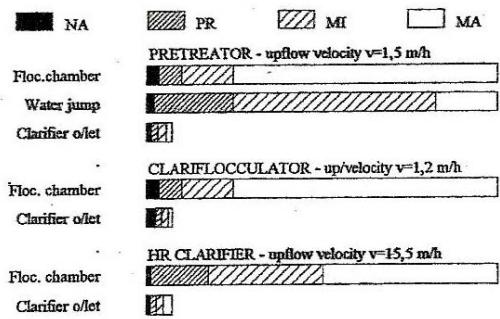 Figure 22: Particle size-fraction distribution in water purified by different clarifier systems, calculated from turbidity
### e) Large Capacity HR Clarifiers at the Saulspoort Waterworks
At the end of the seventies, the City Council of Bethlehem approved the installation of a $20\mathrm{ML.d^{-1}}$ new waterworks to purify Saulspoort Dam water. The intended ultimate design capacity of the waterworks was $60\mathrm{ML.d^{-1}}$, the design of the purification system should make provision for semi-automatic operation and allow for a plant overload of $50\%$.
The waterworks staff had gained a good knowledge and experience of the HRCT. The pilot HR clarifier proved to be efficient, simple and user friendly in operation and, unlike the old waterworks, allowed the process controllers (plant operators) to remain master of the plant at all times. Owing to this outstanding experience with the HRCT, the City Council decided to accept the concept of the HRCT for their new Saulspoort waterworks.
The design parameters of the HR clarifiers installed at the Saulspoort Waterworks (Figure 23) are as follows:
$\succ$ Design capacity
$$
Q = 1 0 \mathrm {M L}. \mathrm {d} ^ {- 1} = 4 1 7 \mathrm {m} ^ {3}. \mathrm {h} ^ {- 1},
$$
Diameter
$$
D _ {c} = 8 6 5 0 \mathrm {m m},
$$
> Height of the clarifier
$$
H _ {C} = 8 2 0 0 \mathrm {m m},
$$
> Intensity of agitation in the Flocculator
$$
\overline {{G}} = 1 0 0 - 4 0 0 \mathrm {s} ^ {- 1}
$$
Total clarifier volume
$$
V _ {C} = 3 1 5 \mathrm {m} ^ {3},
$$
Area of the sludge blanket at its separation level
$$
F _ {S B} = 3 7. 9 \mathrm {m} ^ {2},
$$
> Upflow velocity at the sludge blanket level
$$
v _ {U P} = 1 1. 0 \mathrm {m . h} ^ {- 1},
$$
$\succ$ Separation area at the sludge thickener
$$
F _ {S T} = 3 3. 0 \mathrm {m} ^ {2},
$$
Retention time in the clarifier at design flow
$$
T _ {C} = 4 5 \min ,
$$
Average concentration of drained sludge
$$
C _ {S} \quad > \quad 4 0 g. L ^ {- 1}.
$$
- The clarifier de-sludge pipe is fitted with a pneumatically operated butterfly valve. Operation of this valve can be initiated either manually or by a timer.
- The water softened for dissolution of OAA in 0.025 N NaOH electrolyte is prepared in in situ.
- > OAA is dissolved at a stock solution concentration $1.0\mathrm{g.L}^{-1}$, and the solution matures for 24 hours before its use.
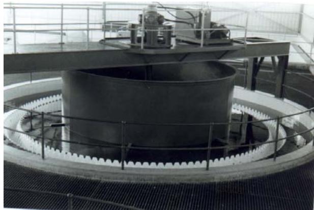 Figure 23: The Saulspoort waterworks - the HR clarifier, design capacity 10 ML.d-1
### f) Performance Results
The Saulspoort waterworks was put into operation in 1980 [32]. It was commissioned using both types of aggregation agent, namely aluminium sulphate and Floccotan. It should be pointed out that ferric chloride, because of greater raw water alkalinity is a more efficient coagulant than aluminium sulphate; however, aluminium sulphate was used during plant commissioning because ferric chloride was not available.
Commissioning of the waterworks was carried out under two sets of four runs, each set verifying certain aspects of the clarifier operation and performance. The operation with Floccotan was aimed at proving the importance of completion of aggregation in the Flocculator $(\gamma = 1)$ before the addition of OAA. During these trial runs the clarifiers operated at an upflow velocity $v_{UP} = 6.5$ and $12.0\mathrm{m.h^{-1}}$ and $\gamma = 0.34$ to 1.0. The significance of the degree of aggregation ( $\gamma$ -value) achieved before the addition of OAA on the quality of purified water is best demonstrated by comparing the differences in the residual turbidity produced by the nonaggregated (non-separable) particles and measured at the outlet from the flash mixer $C_{FM}F$ and the outlet from the clarifier $C_C F$. Evidently the lower the $\gamma$ -value the poorer the purified water quality, while the hydraulic loading of the clarifier has no effect in this regard. The results obtained are shown in Table 3.

Table 3: The HR clarifiers commissioning results from the first set of tests [33]
<table><tr><td>Source of raw water:</td><td>Saulspoort Dam</td></tr><tr><td rowspan="2">Raw water turbidity:</td><td>C0= 36 - 115 NTU</td></tr><tr><td>C0F = 23 - 42 NTU</td></tr><tr><td>Aggregation agent:</td><td>Floccotan</td></tr></table>
<table><tr><td rowspan="3">RUN No.</td><td rowspan="3">PERIOD OF OPERATION</td><td rowspan="3">UPFLOW VELOCITY \(V_{UP}\)[m.h-1]</td><td rowspan="3">\(Y\)-VALUE [-]</td><td colspan="2">DOSING RATE</td><td colspan="5">TURBIDITY</td></tr><tr><td rowspan="2">FLOCCOTAN[mg.L-1]</td><td rowspan="2">SF-A110[mg.L-1]</td><td colspan="2">RAW WATER</td><td rowspan="2">FLASH MIXER \(C_{FM}\)FNTU</td><td colspan="2">CLARIFIER</td></tr><tr><td>\(C_0\)NTU</td><td>\(C_0\)FNTU</td><td>\(C_c\)NTU</td><td>\(C_c\)FNTU</td></tr><tr><td>1</td><td>4/9 – 15/10/80</td><td>6.5</td><td>1.00</td><td>12</td><td>0.05</td><td>45</td><td>24</td><td>-</td><td>1.4</td><td>0.35</td></tr><tr><td>2</td><td>15/10 – 21/12/80</td><td>12.0</td><td>0.85</td><td>12</td><td>0.05</td><td>36</td><td>23</td><td>-</td><td>2.1</td><td>0.52</td></tr><tr><td>3</td><td>21/12 – 10/2/81</td><td>12.0</td><td>0.34</td><td>20</td><td>0.10</td><td>115</td><td>42</td><td>1.3</td><td>5.8</td><td>0.98</td></tr><tr><td>4</td><td>10/2 – 20/2/81</td><td>12.0</td><td>0.75</td><td>20</td><td>0.10</td><td>115</td><td>42</td><td>1.3</td><td>2.8</td><td>0.57</td></tr></table>
During the second set of commissioning runs with aluminium sulphate the clarifiers were operated at four different hydraulic loadings under optimized reaction conditions and at almost completed aggregation, $\gamma \approx 1.0$. These runs were aimed to verify the clarifier's capability to operate safely and efficiently up to a $50\%$ hydraulic overload, i.e. up to an upflow velocity $v_{UP} = 16.5 \, \text{m.h}^{-1}$. The results obtained are shown in Table 4.
Table 4: The HR Clarifiers Commissioning Results from the Second Set of Tests [33] Source of raw water: Saulspoort Dam Aggregation agent: Aluminium sulphate Raw water turbidity: $C_0 = 65 - 70$ NTU $C_0F = 28 - 34$ NTU
<table><tr><td rowspan="3">RUN No.</td><td rowspan="3">PERIOD OF OPERATION</td><td rowspan="3">UPFLOW VELOCITY \(V_{UP}\) [m.h-1]</td><td rowspan="3">\(V-\)VALUE</td><td colspan="2">DOSING RATE</td><td colspan="3">TURBIDITY</td></tr><tr><td rowspan="2">\(Al_2(SO_4)_3\) [mg.L-1]</td><td rowspan="2">SF-A110 [mg.L-1]</td><td>RAW WATER</td><td colspan="2">CLARIFIER</td></tr><tr><td>\(C_0\) NTU</td><td>\(C_c\) NTU</td><td>\(C_cF\) NTU</td></tr><tr><td>1</td><td>4/11 – 5/11/81</td><td>11.1</td><td>0.98</td><td>75</td><td>0.10</td><td>68</td><td>1.8 – 3.5</td><td>0.20 – 0.22</td></tr><tr><td>2</td><td>5/11 – 7/11/81</td><td>13.6</td><td>0.93</td><td>72</td><td>0.12</td><td>65</td><td>3.2 – 5.5</td><td>0.20 – 0.25</td></tr><tr><td>3</td><td>7/11 – 9/11/81</td><td>15.0</td><td>0.99</td><td>73</td><td>0.15</td><td>70</td><td>4.0 – 7.0</td><td>0.22 – 0.28</td></tr><tr><td>4</td><td>9/11 – 12/11/81</td><td>16.5</td><td>0.95</td><td>78</td><td>0.18</td><td>68</td><td>4.0 – 7.0</td><td>0.22 – 0.30</td></tr></table>
The residual turbidity produced by non-aggregated particles and measured in the clarifier outlet was low with small differences irrespective of the upflow velocity. This is because, the $\gamma$ -value was very close to 1 and the alum dosage to optimum. The performance results proved that the clarifier can consistently purify water to a good potable quality, in terms of the National Standard (SANS 241), even at the highest hydraulic loadings and shortest retention times providing $\gamma = 1$.
It can be concluded that the waterworks commissioning was very successful. The clarifier performance met all performance expectations and demonstrated that the HRCT can be the technology of the future.
At the beginning the waterworks was operated with Floccotan and a filtrate of sparkling clarity was produced, even at the highest flow, corresponding to an upflow velocity $v_{SB} = 16.5 \, \text{m.h}^{-1}$ in the clarifier. During 1982 it was discovered by Van Steenderen [34] that Floccotan presents a potential health risk. Therefore, due to a dedicated check-up by Van Steenderen [35](Table 5) it was discovered that the concentration of organohalogens in the raw water increased in the filtrate from $TOH_{0} = 37 \, \mu\text{g} \, \text{CHCl}_{3} \cdot \text{L}^{-1}$ to $TOH_{F} = 52 \, \mu\text{g} \, \text{CHCl}_{3} \cdot \text{L}^{-1}$. The $TOH_{P}$ potential value increased even more from 878 to $1209 \, \mu\text{g} \, \text{CHCl}_{3} \cdot \text{L}^{-1}$ as shown in Table 5. The $TOH$ and $TOH_{P}$ values in potable water should be lower and not exceeding that of the raw water. Therefore, Floccotan was immediately replaced with ferric chloride applied under optimized reaction conditions with regard to the monitored impurities [3].
Table 5: Secondary organic pollution of the purified water produced by natural OC (Floccotan) at the Saulspoort Waterworks (Van Steenderen) [35]
<table><tr><td>Point of measurement</td><td>DOC [mg C.L-1]</td><td>TOH [μg CHCl3.L-1]</td><td>TOHP [μg CHCl3.L-1]</td></tr><tr><td>Raw water</td><td>5.2</td><td>37</td><td>878</td></tr><tr><td>Flocculated water</td><td>4.8</td><td>-</td><td>1211</td></tr><tr><td>Filtrate</td><td>4.6</td><td>52</td><td>1209</td></tr></table>
Regrettably based on the advice of an organic coagulant supplier and without receiving any technological justification and proof that the water would not be purified to a poorer quality, the Municipality replaced ferric chloride with organic coagulant L-100 (assumed to be Poly DADMAC). Appraisal of treatability of the raw water attainable with ferric chloride and L-100 is shown in Table 6.
Table 6: Coagulation efficiency and treatability of the Saulspoort Dam water attained by optimized dosages of $\mathrm{FeCl}_3$ and L-100 (organic coagulant) [36]
<table><tr><td>Coagulant</td><td>Dosage</td><td>pH</td><td colspan="2">Turbidity</td><td colspan="2">NOM (CODMn)</td><td>Me</td><td colspan="2">Degree of destabilisation δ</td></tr><tr><td></td><td></td><td></td><td>C</td><td>CF</td><td>C</td><td>CF</td><td>C</td><td>Tu</td><td>NOM</td></tr><tr><td></td><td>[mg.L-1]</td><td>[-]</td><td>NTU</td><td>NTU</td><td>mg O2.L-1</td><td>mg O2.L-1</td><td>mg.L-1</td><td>%</td><td>%</td></tr><tr><td rowspan="2">Raw water at dosing point of:</td><td>FeCl3</td><td>7.85</td><td>66</td><td>33</td><td>5.93</td><td>5.34</td><td>-</td><td>-</td><td>-</td></tr><tr><td>L-100</td><td>7.95</td><td>74</td><td>38</td><td>6.18</td><td>5.42</td><td>-</td><td>-</td><td>-</td></tr><tr><td colspan="2">Water purified by:</td><td></td><td></td><td></td><td></td><td></td><td></td><td></td><td></td></tr><tr><td>FeCl3</td><td>100</td><td>5.8</td><td>0.25</td><td>0.18</td><td>1.45</td><td>1.40</td><td>0.02</td><td>0.996</td><td>0.755</td></tr><tr><td>L-100</td><td>1.5</td><td>7.92</td><td>3.0</td><td>1.6</td><td>4.48</td><td>4.41</td><td>-</td><td>0.959</td><td>0.275</td></tr></table>
It is evident from the comparison of the values of the degree of destabilization $\delta$ (coagulation efficiency) and the quality of purified water that L-100 is not an equivalent replacement for ferric chloride. This is because the efficiency of organic pollution removal is extremely poor and L-100 cannot purify water to the wholesome potable quality suitable for a lifelong consumption.
Due to the influx of people from the Kingdom of Lesotho at the end of the eighties, the waterworks operated up to a $50\%$ hydraulic overload for about 5 years. During this time the clarifiers were operating between $\nu_{UP} = 11.0$ and $16.5\mathrm{m.h^{-1}}$ until 1993, when the waterworks was extended to the present capacity of 40 ML.d $^{-1}$.
### g) Mechanical Dewatering of the HR Clarifier Sludge
The suitability of sludge produced by the HR clarifiers for mechanical dewatering by centrifugation was investigated (Figures 24,25). The tests were carried out with a Sharples PM 30000 Polymizer centrifuge in March 1981. The clarifier sludge was produced from raw water having a turbidity $C_0 = 115$ NTU using Floccotan as coagulant under the IHDS process at $\overline{G} = 200\mathrm{s}^{-1}$ followed by the POA process with SF-A110 at a dosage
$D_{\text{OAA}} = 0.07 \, \text{mg.L}^{-1}$. The concentration of sludge discharged from the clarifier was about $40 \, \text{g.L}^{-1}$ (4.0%).

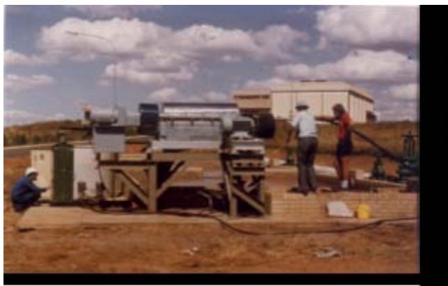
Figure 24: Sharples Polymizer 30000 centrifuge at the Saulspoort waterworks
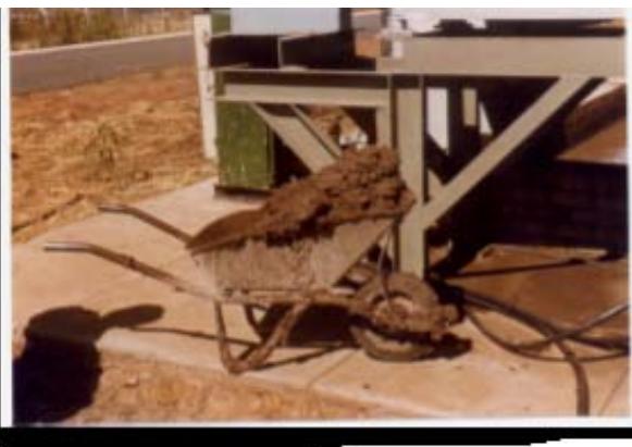 Figure 25: Centrifuge cake produced from HR clarifier sludge - cake dry solids
$34,4\%$ w/w, DOAA = 0,68 kg. (tss)-
The polymer LT-26 (a low toxicity grade recommended by Allied Colloids) was used to condition the clarifier sludge; it was dissolved in 0.025 N NaOH electrolyte. The concentration of the LT-26 solution was $1.0 \, \text{g.L}^{-1}$. The optimum feed rate of sludge to the centrifuge was established at $5.4 \, \text{m}^3 \cdot \text{h}^{-1}$. The centrifuge operated at a bowl speed of 3150 RPM and a scroll differential speed of 8.2 RPM [37]. The solids content in the sludge discharged from the centrifuge, and the solids concentration in the liquid discharged from the centrifuge, were measured.
Two tests using different LT-26 dosages were carried out. In both cases, sludge of spadeable consistency were discharged from the centrifuge. At LT-26 dosage $D_{OAA} = 0.68 \mathrm{~kg} / \mathrm{tss}$ the discharged sludge contained $34.4\%$ w/v dry solids and the liquid discharged contained $120 \mathrm{mg} \mathrm{SS} \cdot \mathrm{L}^{-1}$. When the LT-26 dosage was reduced to $D_{OAA} = 0.37 \mathrm{~kg} / \mathrm{tss}$, the sludge discharged was less thick, nevertheless contained $31.2\%$ dry solids and the liquid discharged was tinged brown containing $370 \mathrm{mg} \mathrm{SS} \cdot \mathrm{L}^{-1}$ [37]. This excellent economic dewatering properties of the clarifier sludge is yet another significant benefit of the HRCT.
### h) Filterability of OAA Formed Agglomerates
The agglomeration of aggregates and deep-bed filtration are interrelated processes as the effectiveness of filtration is determined by the properties of the suspension formed in the preceding processes. However, the properties of agglomerates that are favorable for effective sedimentation may not be the most suitable for economic filtration and vice versa [38].
The purpose of agglomeration is not only the formation of a rapidly settleable suspension but also the formation of a suspension that is effectively and economically filterable to achieve long filtration cycles.
The filterability of the OAA formed agglomerates could not be investigated under the pilot HR clarifier operation. This could only be established during the operation of the Saulspoort waterworks. Similarly, the rise rate of filter headloss resulting from OAA application could not be assessed at the design stage. Therefore, an operational water height of $1500\mathrm{mm}$ above the filter bed was designed to produce an adequate safety margin for the operational pressure head to prevent operation under sub-atmospheric pressure conditions. Under these conditions the length of filtration cycle was longer than seven days. For hygienic reasons however, the length of filtration cycle was limited to a maximum of 72 hours. At the end of the reduced cycle the filter head loss did not exceed $1000\mathrm{mm}$ and on average it was below $600\mathrm{mm}$.
### i) The Saulspoort Waterworks
The remarkable benefit of the HRCT is the major reduction in the footprint and compact layout of the waterworks compared to traditional designs. It efficiently solved operational problems such as the elimination of well-known detrimental effect of the sun and wind on the performance stability of the clarifiers as well as the harsh climatic conditions that exist at the waterworks site, by the installation of a fully roofed-over waterworks (Figure 26). Further benefits resulting from the roofed-over plant are steady ambient conditions for the operation of the plant and equipment and for a pleasant working environment.
Another essential component of this waterworks is the inclusion of staff housing for the operating personnel. This feature together with the simple operation and effective functioning of the waterworks are the reasons for an almost non-existent staff turnover.
The Saulspoort waterworks (Figure 26) consists of three Buildings attached and mutually interconnected, namely:
- > Administration and Operation Building,
- $\succ$ Technology Building,
- Pump Building.
The Administration and Operation Building is sized to service the ultimate waterworks capacity of 60 ML.d $^{-1}$. Buildings of Technology and Pumps are designed to consist of three modules of 20 ML.d $^{-1}$ capacity each.
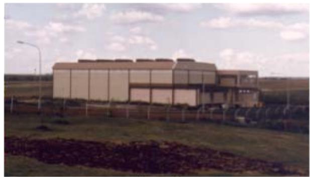
(a)
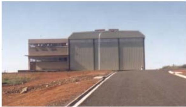
(b)
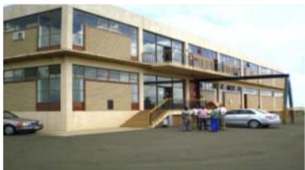
(c)
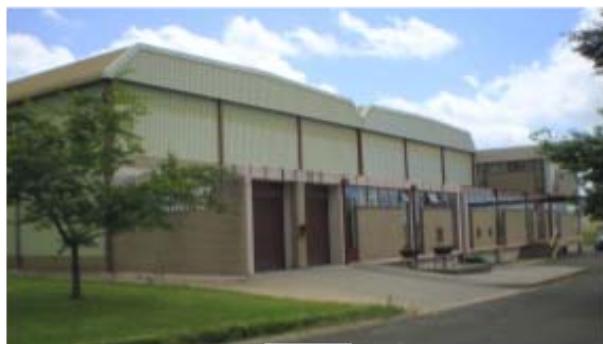
(d) Figure 26: The Saulspoort waterworks
The impact of the reduced footprint on the waterworks layout is best evident by the double story Buildings shown in Figure 26 and their dimensions:
a) Technology Building (18 x 36 m) combined with Pumps Building (6 x 18 m) create one module,
b) Side view of Administration and Operation Building and Building of Technology, one modulus capacity $20\mathrm{ML.d}^{-1}$,
c) Building of Administration and Operation (9.6 x 42 m),
d) Buildings of Technology and Pumps enlarged to two modules - capacity 40 ML.d $^{-1}$.
The Technology Building accommodates raw water flow measurement, hydraulic flash mixer, flow division box, two HR clarifiers and the filtration plant. The filtration plants in both modules consists of four dual media rapid gravity filters. The filters are designed for a filtration velocity $v_{F} = 10 \, \text{m.h}^{-1}$; filter media consist of filter sand $d_{50-S} = 0.9 \, \text{mm}$ and height $L_{S} = 600 \, \text{mm}$ and hydroantrazine $d_{50-A} = 1.6 \, \text{mm}$ and height $L_{A} = 300 \, \text{mm}$.
Operation of the filtration plant proved that a low concentration of suspension, conditioned with a small OAA dosage, entering the filters does not adversely affect the length of filtration cycles. However, the length of filtration cycles is affected by the efficiency of filter backwashing (the intensity of air scour and water backwash should be based on the grain size of the filter medium), and proper filter geometry, which are often ignored in the filter design.
The benefit of HRCT concerning the reduction of capital costs is evident from the reduced waterworks footprint.
## VIII. P-CLARIFIER RECOVERING WATER FROM EUTROPHIC SLUDGE
The City of Salisbury, Rhodesia (now the City of Harare, Zimbabwe) operated the Hunyani waterworks. This waterworks purifiers water from the Hunyani dam. The Hunyani dam water is highly eutrophic and of low turbidity; for most of the time it seldom exceeds 15 NTU.
This raw water was purified in Pulsator clarifiers. These are vertical flow sludge blanket clarifiers. Pulsators were designed to operate at an upflow velocity $v_{UP} = 2.5 \, \text{m.h}^{-1}$. Aluminium sulphate was used as aggregation agent. The maximum sludge concentration in the Pulsator sludge blanket did not exceed $1500 \, \text{mgSS.L}^{-1}$, and its performance was very unstable. Stabilization of the plant performance required up to $50\%$ of the inlet flow to the Pulsators to be drained. In order to maintain the required waterworks capacity, the water contained in the clarifier sludge had to be recovered and delivered to filtration. For this reason the municipality issued a tender for the installation of a plant that would recover $70\%$ of the water from the drained Pulsator sludge; the maximum concentration of the


suspended solids permitted in the recovered water was $25\mathrm{mgSS.L^{-1}}$
For this project, a $13.0\mathrm{m}$ diameter P-Clarifier sized for an upflow velocity of $\nu_{UP} = 3.4\mathrm{m.h^{-1}}$ was proposed and installed by E L Bateman Ltd. The dewatering process was based on the POA of the Pulsator sludge; the SF-A110 was used as the OAA. It was anticipated that OAA dosage would not exceed $D_{OAA} = 1.5\mathrm{mg.L^{-1}}$. Obviously, the actual OAA dosage had to be determined by the quality and the concentration of sludge entering the P-Clarifier and the required SS content at its outlet.
The P-Clarifier performed as follows [40]:
- $\succ$ Capacity
- $\succ$ Concentration of suspended solids at the inlet to P-Clarifier varied between
- Average SF-A110 dosage
- > Upflow velocity
- Average water recovery
- $\succ$ Residual suspended solids in the recovered water
- The content of SS in the P-Clarifier underflow
The storage time of the Pulsator sludge before its delivery to the P- Clarifier had to be very short due to its tendency to become septic.
The P-Clarifier proved capable dewatering the highly eutrophic sludge effectively in a simple and reliable operation. During its service life the volume of the Pulsator's sludge gradually increased as the waterworks capacity expanded. Owing to that the P-Clarifier was finally running successfully at about three times its design capacity [39].
## IX. P-CLARIFIER DESILTING UNDERGROUND GOLD MINE WATER
A pilot P-Clarifier was installed to test its efficiency for removing the high content of suspended
### a) Performance Results
The P-Clarifier was operated from 1976 to 1993, when it was taken out of service [39]. The results below were obtained during the acceptance testing carried out continuously at the maximum rated capacity $Q = 10$ $\mathrm{ML.d^{-1}}$ during March 2 to 9, 1979. The SF-A110 stock solution of a concentration $C_{\mathrm{OAA}} = 1.0 \mathrm{~g.L^{-1}}$ was prepared in 0.025 N NaOH electrolyte prepared from soft water. The OAA stock solution was matured for a minimum of 12 hours before its use.
$$
\begin{array}{l} Q = 1 0 \mathrm{M L}. \mathrm{d} ^ {- 1} \\\mathrm{S S} _ {\text{i n}} = 4 0 0 - 1 0 9 0 \mathrm{m g}. \mathrm{L} ^ {- 1} \\\text{averageSS} _ {\text{i n}} = 8 6 0 \mathrm{m g}. L ^ {- 1} D _ {O A A} = 0.5 \mathrm{m g}. L ^ {- 1} \\v _ {U P} \quad = 3.4 \mathrm{m . h} ^ {- 1} \\R = 82 \% \\\mathrm{S S} _ {\text{out}} \leq 4.0 \mathrm{m g}. L ^ {- 1} \\S S _ {S} = 2.4 2 - 4.0 8 \mathrm{g . L} ^ {- 1} \\\end{array}
$$
solids from the underground mine water before pumping to the surface. Because this clarifier and the OAA dissolving and dosing plant would be installed underground next to the sedimentation system to reduce pumping cost, required the smallest footprint for this system.
 Figure 27: The pilot P-Thickener dewatering underground mine water
The pilot P-Clarifier (600 mm diameter) was installed at No. 10 Shaft, Vaal Reefs Gold Mine and was operated at an upflow velocity $v_{s} = 34.4 \, \text{m.h}^{-1}$ (Figure 27). The content of suspended solids at the inlet to the

P-Clarifier varied up to $20,000 \mathrm{mg} \cdot \mathrm{L}^{-1}$. The OAA (N351) was dissolved in $0.025 \mathrm{~N}$ NaOH electrolyte at a concentration of $0.5 \mathrm{~g} \cdot \mathrm{L}^{-1}$. The flow through the plant was by gravity and varied considerably as it depended on the pumping arrangement from the mine; likewise concentration of suspended solids in the mine water varied considerably. At a $C_{0} = 5,000 \mathrm{mg} \cdot \mathrm{SS} \cdot \mathrm{L}^{-1}$, $D_{\mathrm{OAA}} = 1.5 \mathrm{mg} \cdot \mathrm{L}^{-1}$ and an upflow velocity $v_{\mathrm{s}} = 34.4 \mathrm{~m} \cdot \mathrm{h}^{-1}$ the content of suspended solids at the P-Clarifier outlet was $C_{\mathrm{C}} < 20 \mathrm{mg} \cdot \mathrm{L}^{-1}$.
A significant benefit of the P-Clarifier design is its ability to effectively float, collect and remove oil from the underground water at the top of the agglomeration compartment.
Important Notice
The great potential of HRCT evident from the presented results may probably not be duplicated in full extent as shown in this article. The reason is that the water soluble polymers used in the operation of High Rate Clarifiers were Superflocs provided by Cyanamid Co. of USA which no longer exists. Unfortunately, these Superflocs in the quality provided by Cyanamid Co. are no longer available. We believe the USA Cytec Co. manufactured the Superflocs for Cyanamid Co. and the Cytec Co. was acquired by Kemira Water Solutions, Inc. Based on our experience the polymers now supplied as Superflocs are remarkably of a poorer quality differing from the quality originally provided by Cyanamid Co. as day and night. If Kemira Water Solutions is the manufacturer/supplier of Superflocs they should return the Superflocs to their original quality. If they are not capable of doing it then they should supply the polymers of present-day quality under a different name to prevent any adverse and misleading information to their users.
## X. CONCLUSIONS
1. A new water purification technology, the High Rate Clarification Technology, significantly accelerates the formation of flocculent suspension and its gravity separation never achieved before. This technology consists of two processes, namely the Inline High Density Suspension formation process, which takes place under a very high agitation intensity ( $\overline{G} >> 50 \, \text{s}^{-1}$ ) until the aggregation is completed followed by the Post-Orthokinetic Agglomeration process under which the dense micro-aggregates are agglomerated to large, heavy and rapidly settling agglomerates utilizing water soluble anionic or non-ionic polymers.
2. It was proven that the customary method of application of the water soluble polymers as coagulation and/or flocculant aids results in an impairment of the quality of purified water and the performance of rapid gravity filters. In addition, it does not form the most rapidly settling flocculent
suspension. Therefore, this is not the most effective method for the use of water soluble polymers. The optimum method for the use off anionic and nonionic polymers is when they are applied as agglomeration agents and not as coagulation or flocculation aids, which is present common practice. The agglomeration capability of anionic and non-ionic polymers is influenced by the physical-chemical conditions under which they are dissolved and their solution applied.
3. Degree of aggregation $\gamma$ has been developed as a simple tool for assessing the level of aggregation reached at the point of addition of anionic or nonionic polymers. The optimum is that at which aggregation is completed, $\gamma = 1$; the $\overline{G} T_{0}$ value used for calculation of $\gamma$ value is aggregation agent dependent.
4. Two different types of clarifiers incorporating principles of the HRCT were developed:
a) HR clarifier, a fully fluidized sludge blanket type, incorporating flocculation, sludge blanket, clarified water and sludge thickening compartments,
b) P-clarifier, a circular, horizontal flow, sludge scraper free, high rate sedimentation type clarifier, incorporating the following compartments: flocculation, sedimentation, clarified water and sludge accumulation/thickening compartments; when it should operate as a high rate clarifier the function of the internal Flocculator is changed to the POA process and the Flocculator is installed externally next to the P-Clarifier.
5. A $3.0 \mathrm{~m}$ diameter HR clarifier was continuously operated by waterworks staff for a period of 7 years. Experience gained with the operation of this pilot plant can be summarized as follows:
a) The purified water produced was filtered with waters discharged from three Clariflocculators installed at the waterworks. On average this pilot HR clarifier purified more than $1500\mathrm{m}^3.\mathrm{d}^{-1}$ of dam water and this water was used to cover the waterworks shortfall capacity.
b) The highest operational flow rate of $2877 \, \text{m}^3 \cdot \text{d}^{-1}$ corresponds to an upflow velocity at the sludge blanket level of $25.5 \, \text{m.h}^{-1}$ (83.66 ft.h $^{-1}$ ) and total retention time in the clarifier of 11.9 minutes. The highest concentration of sludge discharged from the clarifier was $73.05 \, \text{g.L}^{-1}$ (7.305%). This indicates the significant positive effect of high intensity agitation on the density of formed flocculent suspension.
c) The operation pilot HR clarifier proved to be very efficient, simple and user friendly and, unlike the old waterworks, allowed the process controller (plant operator) to remain master of the plant at all times.
d) Owing to the outstanding experience with the HRCT, the City Council decided to accept the HRCT and the HR Clarifiers for their new Saulspoort waterworks.
6. Two $10 \mathrm{ML.d}^{-1}$ capacity HR clarifiers were initially installed and about 13 years later another two HR clarifiers were installed. The experience gained with operation of this waterworks can be summarized as follows:
a) The HR clarifiers were designed for an upflow velocity of $11.0\mathrm{m.h^{-1}}$ and retention time of 45 mins. However, they were successfully operated for 6 years at an upflow velocity between 11.0 and 16.5 $\mathrm{m / h^{-1}}$, retention time in the clarifier between 45 and 30 minutes and consistently produced a very good quality purified water, when a hydrolyzing coagulant was used. The use of organic coagulants proved they are not an equivalent replacement for the hydrolyzing coagulants.
b) The operation of the waterworks also proved, the best purified water quality is produced when the degree of aggregation $\gamma = 1$ before addition of OAA.
c) The HR clarifiers sludge can very effectively and economically be dewatered to spadeable consistency by centrifugation.
d) The low dosages of OAA applied to the POA process did not produce any filterability problems because the filter media grading and filter backwashing system were appropriately designed.
7. A $10 \mathrm{ML.d}^{-1}$ P-clarifier designed for POA process was installed for the recovery of water from the Pulsator clarifier sludge; the Pulsators purified highly eutrophic dam water. The experience gained with this installation is summarized as follows:
a) The employer requested to recover at least $70\%$ of water to contain less than $20\mathrm{mgSS.L^{-1}}$ as the recovered water is delivered to filtration. The Pclarifier was successfully recovering $82\%$ of water containing less than $4\mathrm{mgSS.L^{-1}}$.
b) Over the years the P-clarifier flow increased about three times. It was taken out of service after some 25 years of operation.
8. A small pilot P-clarifier designed for desilting of the gold mine underground water was tested. The underground water containing up to about 20,000 mg SS.L $^{-1}$ was pumped to surface. Outstanding performance results were obtained. The underground water containing about 5 000 mg SS.L $^{-1}$ was desilted to contain less than 20 mg SS.L $^{-1}$ at an OAA dosage $D_{OAA} = 1.5 \, \text{mg.L}^{-1}$. Another significant benefit of the P-clarifier is its ability to float, collect and remove oil from the desilted water at the top of the agglomeration compartment.
### ACKNOWLEDGEMENT
The authors wish to gratefully acknowledge:
1. The Rand Water Board (RWB) of Johannesburg, South Africa, for allowing Mr. Polasek
a) To continue testing a great variety of different polymers and thus contributing to the development of the POA method,
b) To Dr R. Wells for convincing RWB management to install the first 3 m diameter pilot HR clarifier.
#### 2. The Edw. L. Bateman Ltd:
a) For installation of the second $3\mathrm{m}$ diameter pilot HR clarifier,
b) For trusting Mr. Polasek with his proposal of using the P-Clarifier for a very delicate application of recovery of water from highly eutrophic sludge.
3. The City of Bethlehem for acceptance of the HRC technology in their new Saulspoort waterworks. In addition, the authors wish to extend their gratitude to the waterworks superintendent Mr W. Coleske and his staff for operating the pilot HR clarifier so successfully that the confidence in the HRC technology was gained and enabled the municipal authorities to issue permission for its implementation in the new Saulspoort waterworks.
4. The City of Salisbury, Rhodesia (now the City of Harare, Zimbabwe) for accepting the P-Clarifier for dewatering the eutrophic sludge from the Pulsator clarifiers installed at their Hunyani waterworks and its staff for the most successful operation of this plant.
Dedication
This article is dedicated to:
- The memory of our dear friend and colleague Dr Silvestr Mutl of the Institute for Hydrodynamics of the Czech Academy of Sciences who developed, among others, the Test of Aggregation which is an indispensable tool for the evaluation of aggregation efficiency as well as the performance efficiency of waterworks. Dr Mutl also contributed, through his knowledge and laboratory investigations carried out with his team of doctoral students, to the explanation of certain characteristics of the micro-aggregates formed under high agitation intensity. Some of these findings were subsequently included in the PhD thesis of Martin Pivokonsky.
- The memory of our dear friend and colleague Dipl. Ing. Arch. Vladimir Selzer who did the architectural design of the Saulspoort waterworks.
- > all open-minded water purification specialists and waterworks operators.
Generating HTML Viewer...
References
38 Cites in Article
Pavel Polasek (1980). Methodology for Evaluating and Monitoring of Waterworks Performance Efficiency —Part 1: Methods and Testing Procedures.
P Polasek,S Mutl (2005). High Rate Clarification technology.
P Polasek,S Mutl (2005). Optimisation of reaction conditions of particle aggregation in water purification – back to basics.
P Polasek,Mutl S (2002). Cationic polymers in water treatment, Part 1: Treatability of water with cationic polymers.
(2002). Cationic polymers in water treatment, Part 2: Filterability of CPE-formed suspension.
A Amran,N Zaidi,K Muda,L Loan (2018). Effectiveness of Natural Coagulant in Coagulation Process: A Review.
P Polasek,Cj Wantenaar (2023). The inability of organic coagulants to purify potable water to its best attainable quality.
Frantisek Hereit,Pavel Polasek (1977). Methodology for Evaluating and Monitoring of Waterworks Performance Efficiency—Part 2: Test of Filterability.
P Polasek (2014). Methodology for evaluating and monitoring of waterworks performance efficiency -Part 1: Methods and testing procedures.
P Polasek (2014). Significance and determination of fraction of non-separable particles of impurities in water purification.
Mooyoung Han,Desmond Lawler (1992). The (Relative) Insignificance of G in Flocculation.
T Camp,C Stein P (1943). Velocity gradient and Internal Work in Fluid Motion.
J Soucek,J Sindelar (1967). The use of a dimensionless criterion in the Characterization of flocculation.
P Polasek (2011). Influence of velocity gradient on optimisation of the aggregation process and physical properties of formed aggregates: Part 1: Inline high density suspension (IHDS) aggregation process.
P Polasek (2011). Influence of velocity gradient on optimisation of the aggregation process and physical properties of formed aggregates: Part 2: Global Journal of Research in Engineering ( E ) XXIV Issue I Version I Year 2024 Quantification of the influence of agitation intensity and time on the properties of formed aggregates.
Kateřina Součková,Tomáš Klír,Michal Hejcman (2002). Medieval Farming Practices in Deserted Villages Can be Determined Based on the Nitrogen Isotopic Signature in Recent Forest Soils.
Martin Pivokonsky,Petra Bubakova,Petra Hnatukova,Bohuslav Knesl (2011). A fluidized layer of granular material used for the separation of particulate impurities in drinking water treatment.
M Pivokonsky,P Vasatova,J Naceradska,Pivokonska L (2020). Koagulace pri uprave vody, Teorie a praxe (Coagulation in water purification, Theory and practice).
B Bolto,Gregory (2007). Organic polyelectrolytes in water purification.
Raid Shatat,Shaik Niazi,Fawaz Batati (2019). Synthetic Polyelectrolytes Based on Polyacrylamide: Non-ionic, Anionic and Cationic Polyacrylamides and Their Applications in Water and Wastewater Treatment: Literature Review.
A Amran,N Zaidi,K Muda,Loan (2018). Effectiveness of Natural Coagulant in Coagulation Process: A Review.
Deb (1965). Theory of Water Filtration -Discussion.
F Hereit,S Mutl,V Vágner (1980). Networks.
Marek Blatný,Iva Šolcová,Petr Květoň,Martin Jelínek,Kateřina Zábrodská,Jiří Mudrák,Kateřina Machovcová (1995). The Influence of Personality Traits on Life Satisfaction Through Work Engagement and Job Satisfaction among Academic Faculty Members.
J Moravec (1969). Intensifikace ciriciho procesu pomoci organickych flokulantu (Intensification of clarification process by organic flocculants).
) Ltd (1971). Plowman, Sir Claude, (1895–5 Sept. 1954), Chairman: Rajciph Ltd, Manufacturing Enterprises Ltd, Sealanes Pty Ltd, Georgenia St Pty Ltd, etc.; Silverwater Rubber Co. Pty Ltd, etc.
P Polasek,F Van Duuren (1981). AWWA C519-25 High-Performance Waterworks Butterfly Valves--3 In. (75mm) Through 60 In. (1,500 mm).
R Van Steenderen,Theron Engelbrecht A (1982). An investigation into the occurrence and concentration of trihalomethanes and their precursors in South African drinking waters.
R Van (1983). Analytical results of water quality.
P Polasek (1995). Optimized conditions for application of organic flocculant aids in water purification.
C Avery (1981). Sharples Polymizer for dewatering sludge from the water purification process.
F Hereit,Polasek P (2014). Methodology for evaluating and monitoring of waterworks performance efficiency -Part 2: Test of filterability.
Nortje N (1995). Private communication.
Smith C D L (1973). Hunyani water augmentation scheme 1971 -Contract ASM 7A.
No ethics committee approval was required for this article type.
Data Availability
Not applicable for this article.
How to Cite This Article
P. Polasek, C.J.Wantenaar. 2026. \u201cHigh Rate Water Clarification Technology\u201d. Global Journal of Research in Engineering - E: Civil & Structural GJRE-E Volume 24 (GJRE Volume 24 Issue E1): .
Explore published articles in an immersive Augmented Reality environment. Our platform converts research papers into interactive 3D books, allowing readers to view and interact with content using AR and VR compatible devices.
Your published article is automatically converted into a realistic 3D book. Flip through pages and read research papers in a more engaging and interactive format.
At present the formation of flocculent suspension and its gravity separation are lengthy processes varying between 3 and 4.5 hours. Consequently this results in high capital costs. Therefore, reconsideration of the kinetics of formation of the flocculent suspension and its effect on the gravity separation of formed suspension was needed. This reconsideration revealed that an unconventional, open-minded thinking was required to develop a new water purification technology capable of solving this problem. This technology will most likely be in direct disagreement with the traditional way of thinking in water purification engineering. The reconsideration project also revealed that the current method for the use of water soluble polymers results in a deterioration of the purified water quality and detrimentally affects the operation of filters. Therefore the development of a method for using these polymers, free of side effects, is also essential. A new technology, the High Rate Clarification Technology, combining two processes developed for addressing the above shortcomings, was developed.
Our website is actively being updated, and changes may occur frequently. Please clear your browser cache if needed. For feedback or error reporting, please email [email protected]
Thank you for connecting with us. We will respond to you shortly.