In this paper, we propose a novel mixed-integer optimization formulation for the optimal design of a reconfigurable antenna inspired by methodology to design frequency reconfigurable patch antennas using multi-objective genetic algorithms (MOGA) genetic algorithm trained by recurrent neural networks and nondominated sorting genetic algorithm II (NGSA-II) improve global optimization capability by diversity detection operation to surrogate a model optimized. Experimental validation of Pareto-optimal set miniaturized multiband antenna designs is also provided, demonstrating a new optimization technique. The oriented design here is practiced for improving reflection coefficient S11, and gain specifications at the frequency band that is achieved by sizing the design parameters using our proposed method in the author’s way the performance parameters were predicted by an iterative process of particle swarm optimization based on feed-forward neural networks (FFNN).
## I. INTRODUCTION
With the increasing demand for smarter antenna design in advanced technology applications, Several antenna structures are suitable for the implementation of reconfigurable antennas, among patch antennas are beautiful structures for various types of reconfigurations.
There are two main domains to be researched for reconfigurable antennas; one is to reconfigure the radiation patterns at fixed operating frequencies, and the other is to reconfigure the operating frequencies with uniform radiation patterns [1]. However, the core of the desired characteristics of a modern reconfigurable antenna is that the design of the antenna has a high real-time requirement for the optimization algorithm to reconfigure the radiation patterns [2] and reduce the interferences over an extensive band. There is a large gap between the present research and the ultimate objective. Our method is illustrated using a miniaturized multiband antenna design example [2,3]. Miniaturized multiband antennas and accelerated automated design optimization of antenna structures using variable-resolution computational models are highly desirable in modern wireless communications.
Integrating the GA-RNN surrogate model with multi-objective genetic algorithms (MOGA) establishes a fast multi-objective inversed optimization framework for multi-parameter antenna structures based on NSGA. NSGA is a dominance-based multi-objective optimization algorithm developed on genetic algorithms, where NSGA-II overcomes some of NSGA's shortcomings [8].
And has excellent performance in 2-3 objective optimization. Finally, a Pareto-optimal set miniaturized reflection coefficient and Gain corresponding to optimized antenna design are presented, demonstrating that the proposed model provides better prediction performance and considerable computational savings [3].
It includes evolutionary algorithms such as the Genetic Algorithm (GA), and Particle Swarm Algorithm (PSO). The signal transmission and reception systems of reconfigurable antennae that increase various diversity methods to improve the quality of the signal and lessen interference in terms of time and frequency [5], further their remarkable advantages such as cost-effective, consolidated effortless fabrication process, conformable, satisfactory bandwidth (BW)[7-6].
The optimization parametric space corresponds to design configuration, and thus, only discrete optimization algorithms can be used and trained by artificial neural networks [4]. These methods have a slower convergence rate than local methods because they can't take advantage of the solution space regularity. Second, the newly added sample operators are well-fitted regarding the optimization objectives to speed up convergence [7].
This paper aims to briefly describe the algorithms and present their application to antenna design problems.
The rest of the paper is organized as follows. Section 2 formulates the data antenna concerning the space design problem. Section 3 presents the performance of the antenna parameters predicted by the model based on the PSO-FNN. Section 4 achieves the output and inputs for the GA-RNN model to estimate the desirable values of S11 and Gain accurately establishes the fast inversed multi-objective antenna optimization framework by combining the result of data antenna offering by HFSS and GA-RNN for the multi-objective optimization improved with NSGA2. Section 5, offers the result of the parameters surrogate the simple model of the patch antenna and gives the result of Pareto optimal design, secondly demonstrates the performance by simulating the fitness and accuracy of neural networks.
## II. METHODOLOGY AND PROBLEM DESCRIPTION
In the first step of the GA process, the initial population is created and the fitness value of each individual in the population is calculated. Then, individuals selected from the population according to the fitness value are crossed and the two parents create a new individual from the individual's genetic codes [3-5]. The search space is expanded by making random changes in the individual's genes with the mutation in the next step.
The next step of Data generation. After confirming the initial antenna shape of the patch antenna, optimal design parameters must be determined. All the optimization processes are performed automatically [10]. For accurately modeling the antenna, a suitable amount of data set includes training, validation, and test data (XTrain, XVal, and XTest) [5], and corresponding desired outputs (YTrain, YVal, and YTest) of recurrent neural networks based on model sequential of Keras and weighting by genetic algorithm process.
MOGA optimization is used in the field of surrogate models mainly to design the characteristics of the patch-feed [5], width, and length with the objective of performance enhancement.
There are two objectives to be satisfied. The first is that the antenna should be impedance-matched over a frequency range [3], The second objective is acceptable to gain performance over the same, with the corresponding cost function as in Equation (1). The overall fitness function is given by Equation:
$$
Ft1 = \frac{1}{N} \sum_{f^2}^{f^1} Ob1(f) \tag{1}
$$
N is the total number of sampling frequencies
$$
Ob1(f) = \left\{ \begin{array}{c} -S11 \text{for} S11 \geq -10db \\0 \text{for} S11 < -10db \end{array} \right\} \tag{2}
$$
The second objective and fitness function given by
$$
Ft2 = \frac{1}{N} \sum_{f1}^{f2} Ob2
$$
$$
Ob2(f) = \left\{ \begin{array}{l} 0 \text{ for } 0.5 \leq \operatorname{Gain}(dB) \leq 5 \\ \operatorname{norm}(\operatorname{Gain}(dB)) \text{ elsewhere} \end{array} \right. \tag{4}
$$
the input reflection coefficient in dB, f1, and f2 are frequencies included in the range of BW, defining the operating band. N is the number of frequency samples taken between f1 and f2.
MOGA consists of n-size parameters in the antenna to be optimized; that is, each chromosome consists of n-size parameters in the antenna to be optimized; for each individual in the new generation represents a space of design parameters.
After determining the suitable antenna configuration, it is time to obtain the optimized design parameters as length (L) and width (W) ground (G). This part aims to enhance the fitness of reflection coefficient S11 within the BW [10]. Hence, advanced multi-objective optimization methods such as NSGA2 are required for multi-objective specifications and the diversity of solutions. When MOGA reaches the set number of iterations, the procedure ends, and the obtained Pareto Front is shown [5-4].
The theoretical values of $W$ and $L$ are given by:
$$
W = \frac {c}{2 f _ {r}} \sqrt {\frac {2}{\epsilon_ {r} + 1}}
$$
$$
L = \frac{c}{f _ {r} \sqrt{\epsilon_ {r , e f f}}} - 2 \Delta L
$$
When $f_{r}$ notes operating frequency and $\epsilon_{r}$ represented the dielectric constant, The efficient patch length is different and its length is increased through $\Delta L$. In general, the multi-objective and multi-parameter antenna designs can be mathematically described as:
min $F(x) = [f1(x),f2(x)\dots,f n(x)]$ Ts.t. $x\in X$ (20 $X\subseteq Rm$
When
$f j(x),(j = 1,2,\dots,n)f j(x),(j = 1,2,\dots,n)$ are $n$ objective functions to be optimized $\mathbf{x}$ present the parameters design $\mathbf{x} =$
$$
\left\{\left(W _ {s}, L _ {s}, W _ {p}, L _ {p}, W _ {k}, L _ {k}, W _ {e}, L _ {e}\right) \right\}
$$
and $F(x)$ is a vector of $m$ objective functions $(g_j(x))$
min $y = f(x)$ s.t. $g(x) = (g1(x), g2(x), \ldots, gm(x)) \leq 0$ where $x = (x1, x2, \ldots, xn) \in x$,
$$
x = \{x \mid l \leq x \leq u \} l = (l 1, l 2, \dots , l n), u = (u 1, u 2, \dots , u n) (1)
$$
$$
U(x) = G(x) = 1
$$
$$
U (x) = \frac {1}{F} \int_ {f 1} ^ {f 2} G (x, f) d f \tag {5}
$$
and U stands for the scalar merit function that quantifies the designer's view concerning the design quality Constraint:
$$
| S 1 1 (x, f) | \leq - 1 0 d B f o r f \in F
$$
$$
\mathrm {U P} (\mathrm {x}) = \mathrm {U} (\mathrm {x}) + \beta 1 \mathrm {c} 1 (\mathrm {x}) ^ {2} \tag {6}
$$
were
$$
c1(x) = \frac{\max(S11(x)+10)}{10}
$$
The functions $c1(x)$ measure constraint violations, whereas $\beta 1$ is the proportionality factor.
where $x$ is the decision vector, $l$ and $u$ are the lower and upper bounds of $x$, $f(x)$ is the objective function [7], and $g(x)$ are constraints. A solution $x$ is feasible if it satisfies all constraints $g(x) \leq 0$, otherwise, it is infeasible, and $y$ is the predicted value using the algorithm MOGA [5].
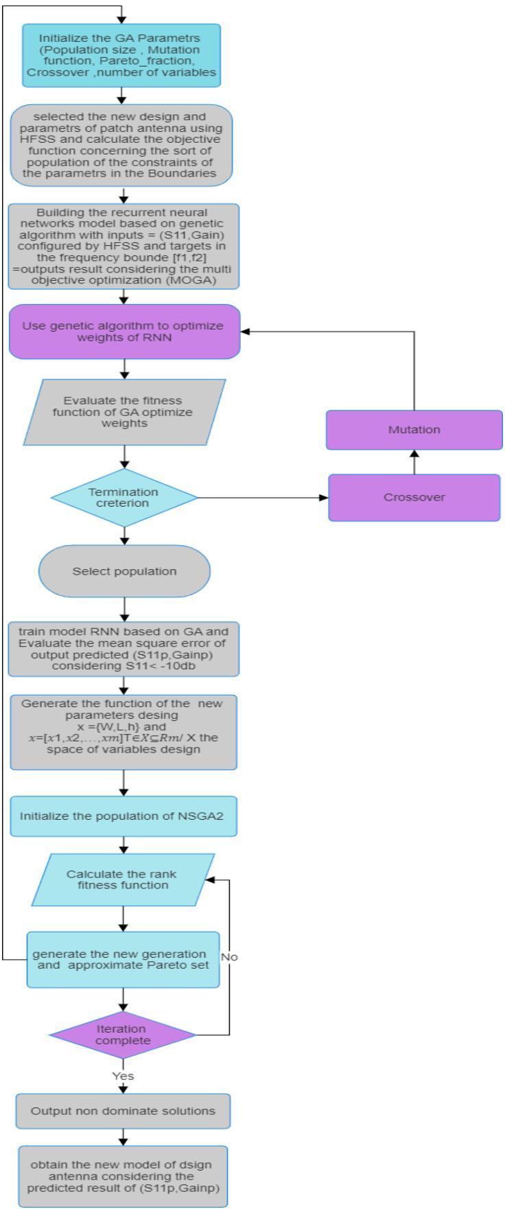
After constructing the initial configuration of the patch antenna, the optimized values for design parameters must be achieved. The brief definitions for this algorithm are as follows the steps:
1. Predefine the design space;
2. Determine the number of neurons in each layer of RNN and the antenna geometry vector $x$;
3. Sample design space using HFSS and acquire the response set y construct the targets;
4. Adjust the RNN_genetic algorithm mapping S11 and Gain by the first iteration 11 of optimization;
5. Construct an $I_{1}$ -MOGA surrogate model $R_{s}(x)$;
6. Optimize the population by MOGA with an NSGA2 surrogate model;
The relative error is defined as$|R(x) - R_s(x)| / |R(x)|$, where$R_s$stands for the surrogate.
The computational model R is simulated in HFSS and corresponds to the experiment parameters design of the patch antenna [8].
Enhanced genetic algorithm (RNN-GA), this redundant information is fed back into the GA's objective function via the recurrent neural network. The neural network learns the optimal weights of the objective function by identifying trends and optimizing weights.
The fitness value of each chromosome represents the accuracy of the network. to evaluate the antenna performance. After confirming the initial antenna shape, optimal design parameters must be determined. All the optimization process is performed automatically in the created platform constructed antenna surrogate model, which is a black box for mapping the relationship between the antenna structure parameters and performance indexes (reflection coefficient S11, gain resonant frequency) [5-8].
In another way, the PSO technique was applied to this problem due to its robust convergence for optimizing the weights [4]. It enhanced the model PSOFNN for predicting the desirable reflection coefficient S11 in BW concerning the range frequency.
Problems that are multimodal, non-differentiable, and discontinuous. HFSS in conjunction with PSO-FNN is used to find the optimal values and targets for all the parameters specified.
### a) Recurrent Neural Networks
Recurrent Neural Network (RNN) is a type of neural network where the output from the previous step is fed as input to the current step. In traditional neural networks, all the inputs and outputs are independent of each other, when it is required to predict the next word of a sentence, the previous words are required and hence there is a need to remember the words. Thus, RNN came into existence, solving this issue with the help of a hidden layer. Recurrent Neural Networks (RNNs) have become a popular technique for language modelling tasks such as speech recognition, machine translation, and text generation [11].
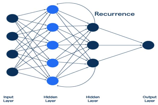
Recurrent Neural Network Figure 1: General View of the Architecture of RNN
b) Artificial Neural Network based on PSO And Genetic Algorithm Used In Optimization Performance And Design Parameters Of Patch Antenna:
The MOGA-HFSS process of the objective function converges results showed that the average fitness approaches the global best value, which is typically a good indication that the optimization run has converged, and no significant improvements are to be expected [6]. This can also indicate that the design tolerates our main objective, which is to obtain good impedance-matching 10dB over two specified frequency bands. the fitness of the design parameter set does not satisfy the constraint equations.
The boundaries and the constraints define the solution space and feasible space and thus account for all the geometrical aspects of the optimization. The aim is to find the optimal solution vector for decision variables. This solution vector must satisfy specific constraints. and non-dominated sorting genetic algorithm II (NGSA-II) to show the effectiveness of our improved MOGA [9].
The space of variables $x$ is the randomly generated population. The population is mutated and crossover to get a new population in the MOGA algorithm. The best fitness value is compared with the desired value and the antenna parameter is updated for the next generation population.
The algorithm is initialized by creating a population of N random neural networks. the fitness functions that force to have a reflection coefficient less than -10 dB give a better bandwidth than those considered the reflection coefficient at the expected resonant frequency or over a frequency band. When multiple objectives in addition to the broadband performance are considered, the cost function needs to be modified by considering all the objectives [6-8].
Optimal design parameters must be determined after configuring the initial configuration of the antenna using HFSS. All the optimization processes are performed automatically in the inputs created concerning the gain and reflection coefficient for the RNN-genetic model.
 Figure 2: Flowchart of the Improved MOGA/NSGA2 with A Dynamically Updatable using GA_RNN Surrogate-Optimized Model
### c) Optimization Performance Parameters Antenna Using Feed-Forward Neural Networks Based on PSO Algorithm
Maintain the Patch reconfigurable antenna. The boundaries and the constraints define the solution space and feasible space and thus account for all the performance parameters of the optimization [8]. acquiring high directivity to obtain the optimal solution established on the action of the swarm that adopts the fitness function.
We have used double PSO optimization. the first time is for creating the NN model with the least error and the second time, while optimizing the NN_model to get the best output parameters [10]. The FFNN-PSO model behaves as The S11 and Gain operated by HFSS. Since the antenna had to be optimized, we have taken this NN model and optimized parameters by feeding different objectives and targets.
#### Algorithm1 PSO_FFNN:
Input: Input The parameters of the Result patch antenna (S11, Gain, frequency):
Outputs: Optimized value of (S11, Gain) maximum iterations: Max, size of
swarm: begin and end, inertia weights: $\omega$ begin and $\omega$ end, acceleration constants: c1, c2, maximum of velocity:
vmax frequency variable f ('2.4,2.8') for each optimization set
Initialization of PSO algorithm:
Social and cognitive coefficients C1, C2;
Inertial weights $W(\mathrm{i})$
Update Velocity V(i);
Populations, Iterations;
#### 1: Set iteration index $k = 0$. Initialize the velocities and positions of n particles, $\omega \gets \omega$ begin - k/Max * (ωbegin - ωend).
- 2: For every particle in the swarm evaluate the fitness function
- 3: Obtain corresponding expectations of the parameter's performance of
- the patch antenna.
- 4: Update the personal best position of each particle, the global best
- position of the swarm Gbest(i), the local best position, and corresponding values. and best fitness
- 5: while $k < \text{Max do}$
- 6: For every Iteration do:
- 7: Obtain corresponding constraints of antenna parameters and update the objective function based on the result obtained using HFSS (S11, Gain).
- 8: if the Current position is the personal best position for this
- particle then
- 9: Update its personal best position
- 10: Request result from HFSS (S11, Gain)
#### 11: evaluate the objective function:
$$
\operatorname{Fit} = - \operatorname{F G} - \min (\operatorname{F G} - 2 0, \operatorname{Gmin}) + \max (| S 1 1 |, 1 0 d B)
$$
Improve in-band matching within the frequency range F
Ensure that in-band matching does not exceed -10 dB in F
$|S11(x,f)| \leq -10$ dB for $f \in F$;
$$
12: Evaluate targets for neural networks, Fit = Targets;
$$
$$
Inputs = {S11, Gmin, F}, net = outputs;
$$
PSOFFNN_run_model (net, inputs);
#### ALGORITHM2 GA_RNN/MOGA_NSGA2:
- X: {XTRAIN, YTRAIN}
1. GENERATE INPUTS AND OUTPUTS OF RNN
- INPUTS $=$ SIZE{S11,GAIN)
- OUTPUTS = SIZE {TARGET (1)}
- TARGETS = {S11s.GAINs};
- NET = RNNNETWORKS (NET, INPUTS, TARGETS);
2. INITIALIZATION OF GA ALGORITHM PARAMETERS
- POPULATION SIZE;
- MUTATION RATE, CROSSOVER
- GENERATION
- NUMBER OF VARIABLES
3. INITIALIZER LEARNING PARAMETERS
- MUTATION POWER, POPULATION SIZE, TRUNCATION SIZE;
4. EVALUATE POLICYINITFUNCTION
5. TRAIN NETWORK FOR THE PARAMETERS (M, POP, TS, I, O, TARGETS)
- EVALOPTI = GA_RNNMODEL (NET, O)
- COMPARE OBJECTIVE FUNCTION ( $\left| {S11}\left( {X,F}\right) \right| \leq - {10}$ DB,FOR $F \in F$ ) OF EVALOPTI
6. EVALUATE THE NEW DESIGN OF THE PATCH ANTENNA USING AN INVERSE PROCESS OF MULTIOBJECTIVE GENETIC ALGORITHM (NSGA2) BASED ON THE RESULT OBTAINED USING THE RNNGENETIC MODEL (S11, GMIN)
7. REQUEST THE RESULTS OF ANSYS HFSS
8. EVALUATE THE DECISION VARIABLES OF PARAMETERS BASED ON THE SPACE OF SOLUTIONS DESIGN PARAMETERS $\in \in \in \square$ $\subseteq \subseteq \subseteq \dots$
## III. SIMULATION AND RESULTS
This section of the paper illustrates that 0.01 GHz increased the frequency of the optimized parameters design and simulation results.
All other values were kept to their default value during the simulation. The figure.1 shows the general structure of the microstrip patch antenna. The proposed antenna is simulated using HFSS Ansys simulation software.

 Figure 3: The General Structure of the Microstrip Patch Antenna and Simulated Model using HFSS Software
Consider the antenna structures paired in Fig. 1 along with their reflection responses $|S11|$, obtained for different optimized parameter values.
Figure 2 shows the predicted S11 by optimization. The predicted S11 well matches the simulated S11 in the results optimized through FFNN based on the PSO algorithm.

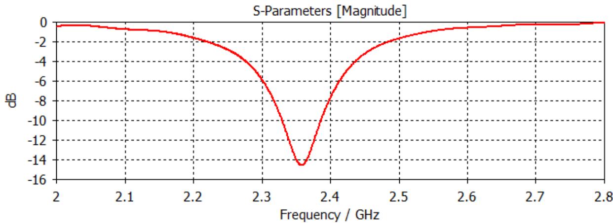 Figure 4: Reflection Responses of Predicted S11 Using PSO_FFNN and Simulated Results in the Dual-Band
Table 1 shows the detailed sizes of the patch antennas. within the range specified of frequency demonstrate the optimized parameters design, indicating that compared to predictive results of s11 and Gain.
Table 1 shows the detailed sizes of the patch antennas. within the range specified of frequency demonstrate the optimized parameters design, indicating that compared to predictive results of s11 and Gain.
<table><tr><td>Parameters Design(mm)</td><td>Boundaries</td><td>Optimized Parameters</td><td>Max |S11| (dB)</td><td>Gain (dB)</td><td>Frequency Range (MHz)</td></tr><tr><td>"Substrate dimension" Ws: 80</td><td>[45, 89]</td><td>87</td><td>-28.1798</td><td>9.10295</td><td>[196.87, 197]</td></tr><tr><td>"Substrate dimension Ls": 80</td><td>[45, 89]</td><td>87</td><td>-27.9522</td><td>9.09736</td><td>[197.75,197.12]</td></tr><tr><td>"Dielectric Height" h: 1.6</td><td>[1, 5.4]</td><td>1.3</td><td>-26.1151</td><td>8.96144</td><td>[198.12,197.87]</td></tr><tr><td>"Antenna patch dimension" Wp: 35</td><td>[19, 63]</td><td>38</td><td>-22.9891</td><td>8.83201</td><td>[198.5,200]</td></tr><tr><td>" Antenna patch dimension": Lp:29</td><td>[16, 30]</td><td>29.4</td><td>-12.6065</td><td>8.82812</td><td>[201.5,210.33]</td></tr><tr><td>"Transmission line x" We: 2.98</td><td>[1.6, 5.3]</td><td>3.8</td><td>-9.25723</td><td>8.9755</td><td>[223.5,223.62]</td></tr><tr><td>"Inset dimension x": Wk: 1.4</td><td>[1, 6.45]</td><td>1.52</td><td>-6.7947</td><td>7.90189</td><td>[223.87,224]</td></tr><tr><td>"Inset dimension y" Lk:7.16</td><td>[7,7.18]</td><td>6.7</td><td>-0.111962</td><td>6.76174</td><td>[224.12,224.25]</td></tr></table>
Changes in the location of the finder solution for particle swarm performance in the later stage of evolution, such as concurrent accuracy for two variables S11 and Gain examine probability for 4 generations.


 Figure 5: The Finder Solution for Particle Swarm Performance and Location in the Later Stage of Evolution, for two Variables S11 and Gain
Consider the antenna structures appaired in Fig. 3 along with their refection responses S11, obtained for different values of parameter optimized and experimented.

 Figure 6: Reflection Responses of Optimized and Experimental Parameters in the Dual-Band Arranged the BW
Multi_objective genetic algorithm optimization is used in conjunction with the surrogate model and prediction of performance parameters of the antenna (S11, Gain, BW). The RA is capable of simultaneously steering its beam in different directions.
The radiation pattern for both parameters simulated and optimized for the patch antenna at two different frequencies has been achieved accordingly.
 Figure 7: The Radiation Pattern for both Simulated and Optimized Parameters Designed for the Patch Antenna
The optimization process is stopped meaning that the desired antenna goals are obtained. At this time, the non-dominated solution set appeared. All solutions in the non-dominated solution set constitute the Pareto front (PF).
Initial Pareto set identified using MOGA executed NSGA2; evaluated the reflection coefficient S11 and Gain from the initial Pareto set, in next step obtained Pareto front in two-objective optimization using high-fidelity-based optimization, shown in Figure 9.
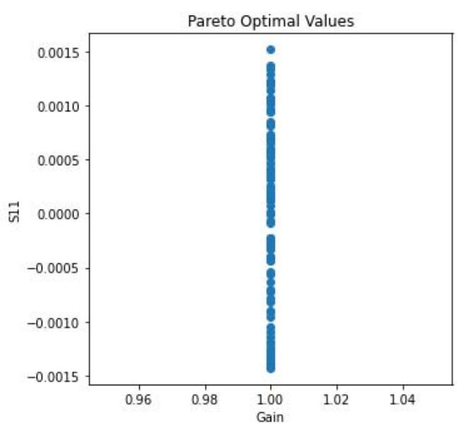
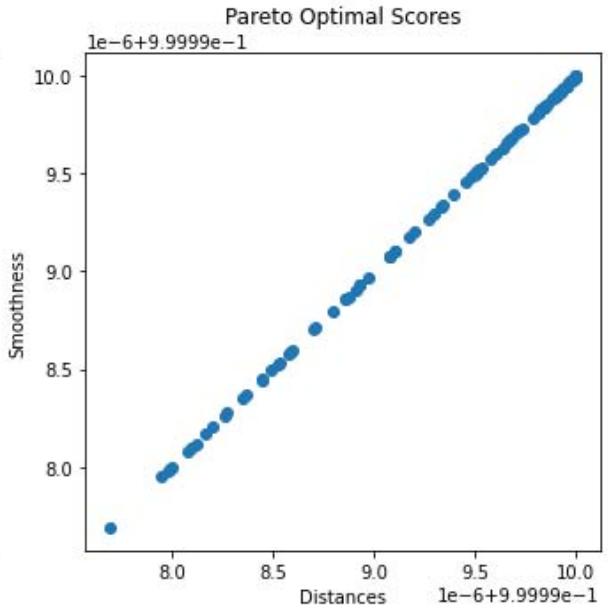 Figure 8: The Selected Pareto Optimal Designs' Reflection Coefficient and Realized Gain Characteristics
Initial Pareto set identified using MOGA executed with NSGA2 for 2 objective functions concerning the performance parameters on the space of design optimized
 Figure 9: Example of Pareto Front in two-Objective Optimization for S11
Whereas Figure 10 provides a fitness function according to the generation of GA and illustrates a comparison of the simulated and measured reflection coefficient and realized gain characteristics.

 Figure 10: The Evolution of Fitness Functions for the GA Algorithm Accurately with Upgrade the Generation, Such as Concurrent accuracy for two Variables S11 and Gain, Examines Probability for 4 Generations
## IV. CONCLUSION
The proposed method is then employed to optimize the antenna parameters and predict the reflection coefficient S11 and gain. At the same time, an additional branch is built to run the simulation tools (e.g., HFSS) and update the data set during the training process instead of constructing the targets for the RNN_GA model.
The results demonstrate that reconfigurable antennas can be designed using an efficient optimization method. We therefore need to combine the objective function with a suitable search procedure.
The main objective of this research is to explore the effectiveness of Artificial Neural Networks (ANN) Based on PSO and GA algorithms in designing and optimizing parameters of the reconfigurable patch antenna and identifying optimal antenna parameters such as S11 and Gain. The study aims to create a fully automated environment for antenna design to minimize the risk of errors and improve the overall efficiency of frequency reconfiguration.
The study aims to demonstrate that the NN-based evaluation algorithms approach can successfully optimize the antenna design process and produce antennas with improved performance.
In our method, two specifications gain and S11 are optimized, and broadside direction with radiation efficiency and optimization of reconfigurable polarization antenna design will be considered as the future work.
Generating HTML Viewer...
References
12 Cites in Article
(2002). Pefanis, Julian 88 Smith, Graham 10 Pétillon, Pierre-Yves 32, 34, 36 Starobinski, Jean 80 Picard, Raymond 23 Steiner, George 78 Piemme, Jean-Marie 45 Stock, Brian 34 Poe, Edgar Alan 9, 27 Stourdzé, Yves 45–6 Pompidou, Georges 47 Pontaut, Alain 5 Poole, Roger 40–1 Takemura, Kenichi 1, 16 Pound, Ezra 56 Tassart, Maurice 105 Texier, Jean 38 Theall, Donald 12, 68, 81, 107–8 Reagan, Ronald 79, 116 Thenot, Jean-Paul 74 Resnais, Alain 87 Thibau, Jacques 46 Rickels, Lawrence 53 Todorov, Tzvetan 50 Riesman, Paul 18–19, 22 Torgovnic, M. 106, 108 Rigby, Brian 6, 17, 33, 60 Trudeau, Pierre 5, 46–7, 91, Robbe-Grillet, Alain 87 103–4 Robert, Gilles 118 Rokeby, David 10 Rosenthal, Raymond 2 Vermillac, Michel 25, 27 Vernay, Alain 50 Virilio, Paul 4, 16, 89, 95–7 Said, Edward 22 Sarick, Lila 14 Sarrazin, Jean 105 Watson, Wilfred 119–20 Sartre, Jean-Paul 26 Weinstein, M. A. 12 de Saussure, Ferdinand 80, 90 Weiss, Peter 83 Schaeffer, Pierre 56–8, 60 Williams, Raymond 34 Schafer, R. Murray 83 Wolf, Gary 13 Schwartz, Eugene 15 Wolfe, Tom 104 Sevette, Christian 11 Wolton, Dominique 47 Smart, Barry 94 Zingrone, Frank 9 ŽiŽek, Slavoj 59, 62.
Shefin Nandana,Shoukhath Design of MEMS Reconfigurable E-Shaped Patch Antenna Design for Cognitive Radio.
Ioannis Gravas,Zaharias Zaharis,Pavlos Lazaridis,Traianos Yioultsis,Nikolaos Kantartzis,Christos Antonopoulos,Ioannis Chochliouros,Thomas Xenos (2020). Optimal Design of Aperiodic Reconfigurable Antenna Array Suitable for Broadcasting Applications.
H Mohammed,F Abdulsalam,A Abdulla,R Ali,R Abd-Alhameed,J Noras,Y Abdulraheem,A Ali,J Rodriguez,Abdelgader Abdalla (2016). Evaluation of genetic algorithms, particle swarm optimisation, and firefly algorithms in antenna design.
Z Wang,J Qin (2022). Multi-Objective Antenna Design Based on BP Neural Network Surrogate Model Optimized by Improved Sparrow Search Algorithm.
Farzad Mir,L Kouhalvandi (2022). Deep neural learningbased optimization for automated high-performance antenna designs.
J Dong,Yingjuan Li,Meng Wang (2019). Fast Multi-Objective Antenna Optimization Based on RBF Neural Network Surrogate Model Optimized by Improved PSO Algorithm.
Slawomir Koziel,Anna Pietrenko-Dabrowska (2023). On nature-inspired design optimization of antenna structures using variable-resolution EM models.
S Koziel,A Pietrenko-Dabrowska (2020). Rapid multiobjective optimization of antennas using nested kriging surrogates and single-fidelity EM simulation models.
Yu Guo,Yukun Wang,Yi Cao,Zhengwei Long (2023). A New Optimization Design Method of Multi-Objective Indoor Air Supply Using the Kriging Model and NSGA-II.
Ratna Sarbagya,Matthew Shakya,Kube (2023). A comparative analysis of the machine learning approach for optimizing antenna design.
Muhammad Al Haromainy,Dwi Prasetya,Anggraini Sari (2023). Improving Performance of RNN-Based Models With Genetic Algorithm Optimization For Time Series Data.
No ethics committee approval was required for this article type.
Data Availability
Not applicable for this article.
How to Cite This Article
Rajaa Amellal. 2026. \u201cOptimization of Frequency Reconfigurable Antenna Parameters Design Using Genetic and PSO Algorithms Based on Neural Networks\u201d. Global Journal of Computer Science and Technology - D: Neural & AI GJCST-D Volume 24 (GJCST Volume 24 Issue D2): .
Explore published articles in an immersive Augmented Reality environment. Our platform converts research papers into interactive 3D books, allowing readers to view and interact with content using AR and VR compatible devices.
Your published article is automatically converted into a realistic 3D book. Flip through pages and read research papers in a more engaging and interactive format.
In this paper, we propose a novel mixed-integer optimization formulation for the optimal design of a reconfigurable antenna inspired by methodology to design frequency reconfigurable patch antennas using multi-objective genetic algorithms (MOGA) genetic algorithm trained by recurrent neural networks and nondominated sorting genetic algorithm II (NGSA-II) improve global optimization capability by diversity detection operation to surrogate a model optimized. Experimental validation of Pareto-optimal set miniaturized multiband antenna designs is also provided, demonstrating a new optimization technique. The oriented design here is practiced for improving reflection coefficient S11, and gain specifications at the frequency band that is achieved by sizing the design parameters using our proposed method in the author’s way the performance parameters were predicted by an iterative process of particle swarm optimization based on feed-forward neural networks (FFNN).
Our website is actively being updated, and changes may occur frequently. Please clear your browser cache if needed. For feedback or error reporting, please email [email protected]
Thank you for connecting with us. We will respond to you shortly.