The Unified Modeling Language (UML) is the de facto standard for object-oriented software model development. The UML class diagram plays an essential role in design and specification of software systems. The purpose of a class diagram is to display classes with their attributes and methods, hierarchy (generalization) class relationships, and associations (general, aggregation, and composition) between classes in one model. A model designing process can include a large number of designers. An issue with this is that the models created may be incorrectly designed. Moreover, there are many concepts in the UML that give rise to potential conflicts, uncertainty, and ambiguity. This paper evaluates the concept of software system model correctness. In this paper,a systematic literature review is conducted to examine how researchers identify problems related to software system model correctness. There are seven papers included in the literature review which cover different approaches for handling model correctness in software systems. The results of this review indicate that UML model correctness is a highly active area of research. There are already some valuable contributions in this direction. However, there are many concepts in the UML with imprecise semantics, which limit the use of the UML and reduce the quality of the UML models. This paper is concluded by providing some directions to identify and prove the mathematical equivalence of the UML class diagram models using standard graph theorems.
## I. INTRODUCTION
UML (Unified Modeling Language) [1] is a graphical modeling language used to specify, simulate, and construct software system components. The UML has been adopted and standardized by the Object Modeling Group [2].
UML is considered the standard for object-oriented software model development that allows modeling of various aspects of complex systems [2]. However, there are many concepts in the UML with imprecise semantics, which limit the use of the UML and reduce the quality of the UML models. Thus, developing technologies for the analysis and verification of UML models is significant to developers who use UML for system modeling.
This work considers the UML class diagram, which is the most fundamental and widely used among all UML models. A Class Diagram provides a static description of system components. The purpose of a class diagram is to display classes with their attributes and methods, hierarchy (generalization) class relationships, and associations (general, aggregation, and composition) between classes in one model [3].
There is number of designers involved in the model designing process who are prone to making mistakes, which gives rise to potential conflicts, uncertainty, and ambiguity. Also, the development of these models is a highly time-intensive process. Therefore, it is extremely important to check the correctness of these models and identify the problems in the early stage of the software design process.
In this paper, seven articles related to the field of software system model correctness were extracted and considered for review. The primary goal of this work is to provide a summary of approaches considered in selected articles, along with the quality of their results and conclusions.
Research articles included in this review are based on several different criteria in the scope of model correctness: problem identified, the approach taken in addressing the identified problem, results and conclusions, differences between the selected articles, and deficiencies in the research of the publications. This review will be useful to understand the important open issues in existing methods and limitations that need to be addressed in the area of model correctness.
The remainder of the paper is organized as follows. Section 2 gives a brief theoretical background of UML models and UML class diagram which is the most fundamental and widely used in UML models. Section 3 describes the review process in the area of verification and correctness of UML models. Section 4 discusses the review summary and important open issues in the domain of software system model correctness followed by the conclusion in Section 5.
## II. BACKGROUND
### a) Theoretical Background
This section covers some of the theories and prior work in the area of UML models along with various aspects of UML class diagrams.
## i. Unified Modeling Language (UML)
UML [2] has been widely accepted as the standard language for modeling and documenting software systems. Their significance has been enhanced with the beginning of the Model-Driven Development (MDD) approach, in which analysis and design models play an essential role in the process of software development. The UML offers a number of diagram forms to describe particular aspects of software artifacts. These diagram structures can be divided into two categories static or dynamic views:
Static view: It describes the structural aspect of the system and its components. It includes objects, classes, attributes, operations, and their interrelationships. The structural view can be represented by class diagrams and composite structure diagrams.
Dynamic view: It describes the behavioral aspect of the system. The dynamic view reflects the changes related to the internal states of individual objects and changes in the system's overall state. This view can be represented by sequence, activity, and state chart diagrams.
## ii. UML Class Diagram
The UML class diagrams are used to represent the static structure of system components [2]. It describes the system structure in terms of classes, attributes, and constraints imposed on classes (operations) and their inter-relationships. Class diagrams are used at the analysis phase to present a view of the static entities in the problem domain, and at the design phase to present a view of the static entities (classifiers) in the solution domain. A class diagram is best described as a set of graph elements connected by their relationships.
Classes in UML models are represented as rectangles. Each class consists of a name, set of attributes, and set of operations on the class's attributes. Figure 1 shows an example of a class diagram consisting of classes, associations (aggregations and compositions), and generalizations.
## iii. UML Association (Aggregation, Association, Composition, generalization)
There are some rules and requirements for combining the classes to construct partial or complete UML class models.
Association — It can be depicted as bidirectional or unidirectional. The association lines indicate the possible relationship between the class entities [4].
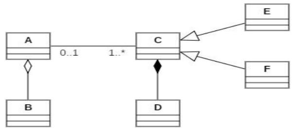 Figure 1: UML Class Diagram
An association represents attributes and objects from the related classes, such as the relationship between class A and class C seen in fig. 1. Association ends can be annotated with labels, known as association end names and multiplicities. For example, multiplicity can be expressed as specific numbers, ranges of numbers, or unlimited numbers, as shown in fig. 1 between classes A and C.
Aggregation $\rightarrow$ An aggregation is represented as an association with a white diamond on one end, where the class at the diamond end is the aggregate (container class). It includes or owns instances of the class (contained class) at the other end of the association [4](e.g., the relationship between class A and B in fig. 1).
Composition $\rightarrow$ It is a special type of aggregation in which instances of the contained class are explicitly owned by instances of the container classes [4]; if an instance of the container class is deleted, the instances of the contained class are also deleted. Fig. 1 shows class C, the container class, and class D, the contained class. It is represented as an association with a black diamond.
Generalization A generalization is represented by an association with a triangle on one end represents, where the class at the triangle end of the association is the parent class of the classes at the other ends of the association, called subclasses [4]. A subclass inherits all of the parent class's attributes, operations, and associations (e.g., subclasses E and F inherit properties of parent class C in fig. 1).
## III. LITERATURE REVIEW
In this section, several studies related to the verification and correctness of UML models are discussed.
### a) Review Process
Seven publications were selected for this study, each covering a distinct technique to dealing with model correctness in software systems. The following is a list of distinct stages that are being considered during the review process for each publication:
1. Problem identified in the selected publication
2. The approach taken in addressing the issue
3. Results and Conclusion
4. Statement of deficiencies in the research of the publication
In AGG: A graph transformation environment for modeling and validation of software [7], the author Taentzer briefly discussed the graph transformation tool, that defines the rule-based manipulation of graphs. Graph grammars and graph transformations are very mature approaches used to generate, manipulate, recognize, and evaluate graphs [8].
Taentzer proposed a graph transformation tool (AGG) [7] which supports the modelling and verification of software. It has visual editors for graphs, graph grammars as well as the formal foundation based on the algebraic approach for graph transformation. Transformation in AGG can be performed using debug or interpretation mode. In debug mode one selected rule is applied exactly once to the current host graph while in interpretation mode whole sequence of rules applied to host graph. AGG also offers support for model validation techniques like graph parsing, consistency checking, along with the conflict detection of graph transformation rules. It consequently implements the theoretical results available for algebraic graph transformation to support their validation.
The authors extended their work and compared AGG to other transformation tools (PROGRES, Fujaba, DiaGen, and GenGED). They found that AGG is the only tool that implements the theoretical results available for algebraic graph transformation.
However, there is number of limitations associated with AGG tool. AGG does not support the represent of aggregation and composition concepts used by the UML meta model. Therefore, the type graph needed to be simplified by using the more generic concept of association. AGG does not provide a satisfactory control structure for organizing and combining rules, also the supplied mechanisms for composing rules were not sufficient to describe model refactoring. Along with that, the specification techniques found in graph grammars and transformation languages were not sufficient, as they do not follow UML concepts.
In [9], Towards formal verification of UML diagrams based on graph transformation, authors Zhao et al. presented a meta-level and highly automated technique that could formally transform UML diagrams for verification. UML has a lack of precise formal semantics [10], which hinders the formal verification and validation of system design. So, transformations of UML models in various mathematical domains such as Petri-nets are significant for the analysis and verification of the UML model.
Zhao et al. suggested an approach for transforming UML diagrams into Petri nets based on meta-modelling and graph transformation techniques [9]. First, they formally transform UML statecharts and behavioral diagrams to Petri nets for verification. Then, they identified three layers of relationship among various UML diagrams: the relationships among the same UML diagram from different contextual instances; the relationships among various diagrams from the same view of a system; and the relationships among various diagrams from different views of a system.
Authors extended their work and proposed a debugging approach to modify the transformation rules according to the concrete semantic constraints through a case study. They have also conducted experiments on the verification of relatively simple UML statechart diagrams. However, a drawback still persists in modeling large complex problems. In this work, the authors only considered experiments on verifying simple UML statechart diagrams. Also, the third layer, which describes the relationship between the diagrams of static structure view and the diagrams of dynamic behavior view, is rarely considered in this work i.e., related to the verification and transformation of UML models. Along with that, author did not consider the diagrams of static view (e.g., class diagram) which is an essential part of UML.
In Verifying UML diagrams with model checking: A rewriting logic-based approach[11], Mokhati et al. presented a framework supporting the automatic translation of UML diagrams into a formal specification and verification using the Maude language. UML allows the modelling of various aspects of complex systems. However, there are many inconsistencies and ambiguities associated with UML models. Therefore, UML suffers from a lack of formal semantics [12].
Mokhati et al. presented an approach for formal verification of static and dynamic features of UML diagrams using object-oriented and concurrent Maude language specifications [11]. In this work, the authors transformed UML models into formal languages and verify the system's dynamic aspects. The authors extended their work by defining some Linear-time Temporal Logic (LTL) properties and used Maude's model checker to validate those properties associated with UML models.
Authors in this workclaimed to transform all the static and dynamic aspects of UML models into formal languages and validating them using Maude's model checker [11]. However, they could only translate simple UML statechart and communication models and a drawback still persist in translating complex dynamic models (statechart and communication models). Along with that, the authors did not mentioned how translation could be done for other static and dynamic models.
In Verification of UML/OCL class diagrams using constraint programming [13], Cabot et al.
suggested an approach for using the Constraint Programming paradigm to verify UML/OCL class diagrams.
UML models become the primary artifacts of the software development process. Unfortunately, formal verification of software models is a difficult process. As a result, verifying the correctness of such models is a key issue. This is also the case when focusing on verifying UML class diagrams extended with Object Constraint Language (OCL). As a consequence, specification and design problems are not recognized until the implementation stage, causing the development process to be more expensive.
In [13], authors presented an approach to translate UML class models annotated with OCL constraints into a constraint satisfaction problem (CSP). The authors briefly discussed translation of UML/OCL classes, associations, generalization sets, and OCL invariants into CSP. A tool based on CSP (UMLtoCSP) is then used to verify a predefined set of correctness properties for the original UML/OCL diagrams. The UML/OCL language combination integrates well with automated inference systems.
The CSP tool supports bounded reasoning about satisfiability, consistency, finite satisfiability, independence of invariants, and partial state completion. It handles class diagrams with multiplicity, class hierarchy, association-class constraints but does not allow multiple inheritance. Along with that, tool does not support all the features in OCL specification, such as constraints on a string.
In Model checking and code generation for UML diagrams using graph transformation [14], Chama et al. developed a formal specification framework that allows automatic translation of UML models into its equivalent Maude code using AToM3 graph transformation tool. UML contains a large number of diagrams that are used to describe various aspects of a software system. However, the developed UML models can contain inconsistencies and uncertainties, which are difficult to detect manually as UML suffers from a lack of formal semantics.
Chama et al. [14] presented a visual modelling based automatic approach and a tool to check UML models using the graph transformations. They considered both static and dynamic models for inconsistency checking. Their idea was to map class diagrams, statecharts, and communication diagrams into an equivalent Maude specification. They used a meta-modelling approach that could help in model checking. The subset of UML diagrams is considered to develop a metamodeling tool AToM3 integrated framework for model checking by transforming them into a rewriting system expressed in the Maude language and graph grammars. The formal verification is performed using the Linear Temporal Logic (LTL) Model
Checker. They also used Maude's model checker to verify objects interactions.
In Chama et al. [14], the UML models used for Maude language and LTL model verification were incorrectly drawn. Since UML models are ambiguous, validated models can be ambiguous as well.
In Towards an automatic evaluation of UML class diagrams by graph transformation [15], Outair et al. presented an approach for evaluating UML diagrams produced by the students during their course work. As the number of university students enrolled in courses is growing, the evaluation of UML diagrams produced by students is often experienced by teachers as a tedious and challenging task. Since UML does not provide the methodology for modeling, the students have difficulties constructing a class diagram. Furthermore, when students construct a UML diagram with several solutions, it might be presented in different ways and points of view. For this reason, the authors proposed an approach to offer assistance to the teacher to evaluate the UML diagrams produced by students. In this work, the authors mainly focused on evaluating the class diagram because it is the most used and considered the most important aspect of object-oriented modeling.
The authors proposed a student diagram assessment system that provides a verification mechanism wherein the teacher manually compares his/her solution with the ones designed by the student. At the end of the comparison process, the system generates a list with the differences and comments that a student can use to improve his/her diagram. The contribution revealed in this work is the proposal of a transformation method of the class diagram into a graph using UML metamodel. In addition, authors considered a case study for a library management system to demonstrate their approach.
Outair et al. discussed a student diagram assessment system where authors considered an example of a model containing a teacher's class diagram and a student's class diagram to detect all differences between them [15]. They have found several differences in class, attribute, method, relationship, orientation relationships, and multiplicities. However, those differences have been listed manually, so there is a chance of uncertainty and ambiguity. Moreover, for graph transformation, the authors considered a library management system case study in which the graph model is designed manually from a UML diagram. These manually generated graph models can be incorrectly designed. Therefore, a tool for verifying the converted graph model is required to ensure the correctness of the generated graph.
In the Automation and Visualization of Program Correctness for Automatically Generating Code [16], Jason developed a Tool using mathematical analysis that can verify the correctness of the generated code from the input specifications in program synthesizer.
Program synthesis systems [17] are used to generate code automatically from given specifications. It can be considered as a tool that can make programs. It involves different applications such as data analysis for air traffic control data, satellite guidance, navigation, and control system. Two program synthesis systems developed by NASA researchers are easy to use, semi-automated, and quick. However, it includes the manual design of graphical system models. The development of these models is highly time-intensive and can be incorrect. The user would require active assistance to refine the specification. The results are not easy to verify manually for a large amount of data. Due to which these systems suffer from an issue that is the correctness of the generated code. Mathematical analysis can be used to correct such models but require a tremendous amount of work.
Jason [16] extended a technique developed by Grant et al. in collaboration with NASA researchers [17] of program correctness (for verification of generated code from the input specifications) by applying it to AUTOBAYES. This approach models the input specifications, the output code, and the relationships between them using UML Class models and OCL constraints. The author used Code Generator, in which input is in the form of a statistical model (class diagram) and output in the form of a program file in the requested language, which can be used to define a relationship between the input and output constraint. Then as a next step, a class diagram, and constraints for both input and output are defined. Then, these constraints were transformed into the formal specification language and analyzed with the USE tool. Finally, the USE Tool checks whether the constraints defined on the class diagram satisfied the model representation or not.
Jason developed techniques for AUTOBAYES in [16], employing UML class diagrams as an input to a code generator to offer code verification. However, the issue still persists in the system as the class diagrams used as an input for verification are manually designed, which can be ambiguous. Moreover, the USE Tool checks whether the constraints defined on the class diagram satisfied the model representation or not. However, USE is not concentrating on the correctness or verification of the class diagrams.
### b) Significant difference in research publications
Table 1 briefly described the differences between the selected research publications. The comparison of selected approaches will be beneficial for researchers to understand existing approaches more efficiently.
For each reference, the following information is listed: the approach or tool used to transform UML models into graphs, supported UML models (static or dynamic), the translation procedure from UML to graph manual, semi-automatic, or automatic), the verification process (manual, semi-automatic, or automatic) and other limitations of the associated method.
Table 1: Significant difference in research publications
<table><tr><td>Reference</td><td>Approach</td><td>Diagram support</td><td>Translation</td><td>Verification</td><td>Limitation</td></tr><tr><td>[7]</td><td>AGG</td><td>UML Models</td><td>Automatic</td><td>Automatic</td><td>It does not support aggregation and composition concepts used by the UML metamodel.</td></tr><tr><td>[9]</td><td>UML metamodel</td><td>UML Statechart diagram</td><td>Automatic</td><td>Automatic</td><td>It does not consider diagram of static view.</td></tr><tr><td>[11]</td><td>Maude Model Checker</td><td>UML Statechart and Communication diagrams</td><td>Automatic</td><td>Automatic</td><td>It does not consider diagram of static view.</td></tr><tr><td>[13]</td><td>UMLtoCSP</td><td>UML/OCL Class diagrams</td><td>Automatic</td><td>Automatic</td><td>It does not support aggregation and composition relationship of UML class models.</td></tr><tr><td>[14]</td><td>AToM3 tool based on Maude Model Checker</td><td>UML Statechart, and Communication diagrams</td><td>Manual</td><td>Automatic</td><td>The UML models used for Maude language and LTL model verification were incorrectly drawn. However, no ambiguities found at the end of verification process.</td></tr><tr><td>[15]</td><td>UML metamodel</td><td>UML Class diagram</td><td>Manual</td><td>Manual</td><td>A manually generated models are used for translation and verification.</td></tr><tr><td>[16]</td><td>USE</td><td>UML Class diagram</td><td>Manual</td><td>Automatic</td><td>Does not provide meaningful feedbackNot efficient with large and complex UML class models</td></tr></table>
In UML metamodel [15], both the translation and verification of UML class models done manually while UML metamodel [10], Maude Model Checker [12], and UML to CSP [13] offer both automated translation and verification procedures, although [10] and [12] do not take static view diagrams into account. UML to CSP [13] supports static diagrams (UML class models) with general OCL constraints but does not consider multiple inheritance or the aggregation and composition relationships in the UML class model.
In [14] authors used the AToM3 tool, which is based on the Maude model checker, although the translation into UML meta model is done manually. Furthermore, the UML models utilized for verification were incorrectly drawn, resulting in ambiguous verified models.
AGG [8] utilizes semi-automatic approach for both the translation and verification procedures of UML models. The only limitation is that it does not support some UML metamodel concepts (e.g., aggregation and composition). USE tool [17] considers a manually generated class diagram as an input for translation while the verification process is automatic.
## IV. REVIEW SUMMARY AND CONCLUSION
There are several studies related to the verification and correctness of UML models identified for this review, of which seven were selected for this work. These studies are selected based on methodology used and level of automation for the translation and verification process in the domain of software system models. The result of this review shows that model correctness is a highly active area of research. There are several approaches proposed in this area. However, it still has some important open issues and limitations e.g., these studies did not provide enough support for verification and correctness of UML class model.
It is important to check and verify the correctness of UML models to enhance its usability. To achieve that goal as a first step, my plan is to consider the UML class diagram, which is the most fundamental and widely used among all UML models. Therefore, future work can concentrate on identifying and proving the mathematical equivalence of features of the UML class diagram models by applying standard graph theorems.
Mathematically equivalency would reduce concepts in the UML class diagram model, thus leading to a better understanding of the model. An approach to resolve this problem is to simplify the semantics of the class diagram through the application of mathematical formality to the definition and usage of class diagram concepts. The applicable mathematical principles result in a reduction of complexity in the UML class diagram model. Along with that, we can eliminate redundant components (e.g., generalization/specialization relationship) by applying mathematical principles and set theory.
A correlating effort of the future work would be proving the correctness of the class diagrams developed with the reduced number of model concepts. A tool that transforms the class diagram into a graph representation and then applies appropriate graph theories to identify anomalies in the class diagram model's design will be developed. Then, this work will be validated by integrating the class diagram correctness technique with an industrial program synthesizer input/output validation process.
By resolving certain limitations and open issues associated with verification and correctness of UML class model, we can produce simplified and formalized concepts of software system modeling notation that will advance learning and appreciation of skills fundamental to producing the next generation of reliable and correct software systems. It will also contribute to the work on program correctness that is complementary to existing work on verifying the synthesizer input/output validation process.
Program synthesizers are used in multiple safety-critical domains; one is that of space exploration. These tools have specification language problems, instance inputs and output a program that implements a solution of the input problem. However, verifying the output with respect to the input has been a challenging area of research. A promising approach lacks proof of correctness of the used UML class diagrams. These issues can be resolved as a part of future work. This work will also be beneficial to software engineering pedagogy, as a simpler set of software modeling components should lead to a greater appreciation of modeling strategies.
Generating HTML Viewer...
References
17 Cites in Article
G Booch,J Rumbaugh,I Jacobson (1997). The Unified Modeling Language, Rational Software Corporation.
(2012). Information technology. Object Management Group Unified Modeling Language (OMG UML).
C Gutwenger,M Jünger,K Klein,J Kupke,S Leipert,P Mutzel (2003). A New Approach For Visualizing UML Class Diagrams.
S Pfleeger,J Atlee (2010). Pfleeger’s Approach to Software Metrics Tool Evaluation.
J Spivey,J Sanders,J (1992). The Z notation.
B Potter,J Sinclair,D Till (1996). An Introduction to Formal Specification and Z 2nd ed.
G Taentzer (2003). AGG: A graph transformation environment for modeling and validation of software.
Grzegorz Rozenberg (1997). Handbook of Graph Grammars and Computing by Graph Transformation.
Y Zhao,Y Fan,X Bai,Y Wang,H Cai,W Ding (2004). Towards formal verification of UML diagrams based on graph transformation.
G O'regan (2017). Concise Guide to Formal Methods: Theory, Fundamentals and Industry Applications.
Farid Mokhati,Patrice Gagnon,Mourad Badri (2007). Verifying UML Diagrams with Model Checking: A Rewriting Logic Based Approach.
Gianna Reggio,Roel Wieringa (1999). Thirtyone Problems in the Semantics of UML 1.3 Dynamics.
Jordi Cabot,Robert Clariso,Daniel Riera (2008). Verification of UML/OCL Class Diagrams using Constraint Programming.
Wafa Chama,R Elmansouri,A Chaoui (2012). Model Checking and Code Generation for UML Diagrams Using Graph Transformation.
L Outair,T Abdelouahid,Mariam (2014). Towards an automatic evaluation of UML class diagrams by graph transformation.
K Dailey,R Jacobson,J Kim,S Mallik,A Brooks (2020). PROBING CLINICAL RELEVANCE: ESTABLISHING THE EFFICACY OF C. NOVYI AGAINST A PANEL OF 2D CULTURED PANCREATIC CANCER CELLS.
E Grant,J Whittle,R Chennamaneni (2003). Checking Program Synthesizer Input/Output.
No ethics committee approval was required for this article type.
Data Availability
Not applicable for this article.
How to Cite This Article
Kruti P. Shah. 2026. \u201cSoftware System Model Correctness using Graph Theory: A Review\u201d. Global Journal of Computer Science and Technology - H: Information & Technology GJCST-H Volume 23 (GJCST Volume 23 Issue H1): .
Explore published articles in an immersive Augmented Reality environment. Our platform converts research papers into interactive 3D books, allowing readers to view and interact with content using AR and VR compatible devices.
Your published article is automatically converted into a realistic 3D book. Flip through pages and read research papers in a more engaging and interactive format.
The Unified Modeling Language (UML) is the de facto standard for object-oriented software model development. The UML class diagram plays an essential role in design and specification of software systems. The purpose of a class diagram is to display classes with their attributes and methods, hierarchy (generalization) class relationships, and associations (general, aggregation, and composition) between classes in one model. A model designing process can include a large number of designers. An issue with this is that the models created may be incorrectly designed. Moreover, there are many concepts in the UML that give rise to potential conflicts, uncertainty, and ambiguity. This paper evaluates the concept of software system model correctness. In this paper,a systematic literature review is conducted to examine how researchers identify problems related to software system model correctness. There are seven papers included in the literature review which cover different approaches for handling model correctness in software systems. The results of this review indicate that UML model correctness is a highly active area of research. There are already some valuable contributions in this direction. However, there are many concepts in the UML with imprecise semantics, which limit the use of the UML and reduce the quality of the UML models. This paper is concluded by providing some directions to identify and prove the mathematical equivalence of the UML class diagram models using standard graph theorems.
Our website is actively being updated, and changes may occur frequently. Please clear your browser cache if needed. For feedback or error reporting, please email [email protected]
Thank you for connecting with us. We will respond to you shortly.