Tilt and Swivel Vertical Axis Wind Turbine for High Speed Regions on or Off Shore. Model Rotor(s) Experiments Lead as Instructive Scaffold to the Prototype
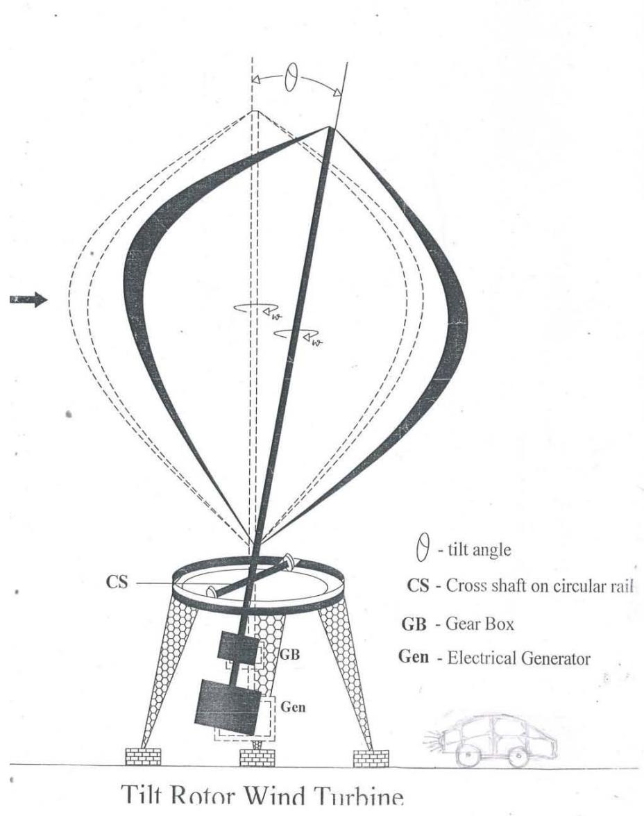
To harness high velocity and fluctuating wind, this new tilt & swivel type vertical axis rotor, as an original idea is investigated. If the conventional anchoring of its top end with guy wires to the ground is simply done away with, the rotor axle becomes a cantilever; requires it to be more rigid, strong and hence heavy. Instead, the lower end of the axle is modified with fulcrum and the rotor is kept upright with the counterweights. Hence the whole balanced assembly of rotor and generator located on opposite ends, can easily tilt about the turnnion, in tune with the wind speed. Counter weight to the rotor can include additional dead weights, along with the generator and gear train. By automatic tilting, the rotor can work through and up to higher cut-out wind speed. Change of wind direction causes the axle to swivel and align for the continued smooth rotor operation. Hence both the tilt and swivel freedom of the vertical axle/axis, renders a complete new design of the wind turbine for high speed regions up to 50 m/s.
## I. INTRODUCTION
Horizontal Axis wind Turbines (HAWT) have been popular for large scale power generation right from the beginning. Favourable turbulence intensity and higher wind velocities over the sea, encourages offshore wind farms as well [1], [4]. However, several practical issues such as wing production of airfoil blade type, logistic and assembling difficulties should also be addressed along with the impact on environment and economy [1]. Since the
$\pmb{R}$ Publishing of this research (a decade old) due to its growing relevance globally and hence terming it as "Rubric report 2023" is explained as an attachment.
stiffness is not increased proportionately, as the wind turbines grow in size, the big structures become severely dynamical sensitive. Nonlinear systems may experience almost periodic and even chaotic response[1]. The cantilevered blades with its considerable tip displacements, sometimes fouling against the tower and the nearly solid disc-like high speed rotors taking head on the high wind as thrust load on tower, are the major vulnerabilities of the HAWT. Particularly the blade hitting the tower is the notorious self destruction. And due to the heavy wake rotation issues, the spacing between the turbines has to be more, resulting in larger farm area for the same power capacity[1].
In the aforesaid (HAWT) uncomfortable background, the vertical Axis Wind Turbine (VAWT) is considered as an alternate candidate especially in the highwind conditions, of course with crucial design changes. It will not certainly be as fast and fiercely efficient as the HAWT; it need not! But with its moderate speed, medium efficiency and rigidly closed shell-like rotor geometry, it can maneuver through the torrential wind currents, safely and easily!. Also the present design strategy can lend the rotor to rock and roll in the turbulent wind and find its own stable rhythm, to sustain and operate continuously[2]. With minimal effort of installation and maintenance, also by working in the high wind for a long duration, Tilt & Swivel type turbine can become a winner in its own right. As for its safety beyond the cut-out wind speed, the rotor may degenerate into either an idle spinner saving the blades by centrifugal stiffening, or can get stopped by brake and become just a drag chute in the wind current. Cantilever blades accidentally dashing against the tower just does not exist here at all! Also the blades of the present turbine is of symmetric airfoil; hence economical in the case of any replacement, if it arises.
a) Physical Experiments, An Overview: Exp (1) Mini Rotor(s) Spin, Tilt and Oscillate
Mini model rotors of Savonius, Darrieus and Gyromill types, of average $0.23\mathrm{m}^2$ size and about 3 kg mass are chosen for the trials. They are cantilever axle supported, with pivot and collar bearing rotors, freely spinning and orbitally oscillating "top-alikes" in the horizontal air flow. The vertical axis of the rotor (12mm dia steel rod of 1.5m length) with its free top-end, is able to rock over the horizontal fulcrum-bar, located at the lower end. The tilt angle of the rotor is proportional to the wind velocity; apart from the tilt, it also oscillates orbitally with a cone angle. Model rotor is kept upright with suitable counter weight at the opposite end of the axle, it also governs the tilt angle along with the wind velocity. The counter weight is about 5 kg dead weight. The turnnion rolls in two simple caller bearings mounted on the high pedestal structure. An electric fan blower is the source of wind flow, locating the models at desired wind flow potential depends directly proportional to its distance from the fan. For each rotor, after it has been self-started or kick-started and reached a steady state, the following data are noted down. The tilt angle of the axle from the vertical, rotors spin rate in r.p.m and the concomitant orbital oscillation rate in c.p.m. The oscillation is just an artifact of projecting the three dimensional trajectory onto the two dimensional visual plane. This experiment was repeated for different orientation of the fulcrum-bar. That is 0, 90 and 45 degrees w.r.t. the horizontal wind direction. As expected, the 90 degree position allows the rotors to gain maximum tilt angle and settle in there, for smooth operations with minimum vibration. The twin needs of the axle's tilt as well as swivel freedom became evident.
### b) Exp(2) Tilting Vertical Axis Rotors on Load Test
Next, two bigger rotors of cantilevered-sleeve types: one Gyromill type and the other modified Darrius type were fabricated and tested in the open air flow field. Electric fan blower is the source of flow, small dynamo meant for bicycle was the token load on the rotor. Both the rotors demonstrated satisfactorily; they are fully tiltable vertical axis types, sans swivel freedom.
### c) Exp(3) Swivel Plus Tilting Rotor on Load Test
Finally, the turbine-to-be was provided with the swivel bearing as well. The fulcrum-bar swivels with support-wheels which were directly mounted and guided on a circular rail, integral with the pedestal structure. Modified Durries type of medium size rotor was preferred of all the three rotor types. This specially fabricated rotor had its vertical axle changed into a rotating shaft, to check the rotor's behavior. During performance, the tilt rotor aligning automatically to the changing wind direction was witnessed; hence the need for swiveling stands vindicated. In this experiment also, the electric fan blower is the flow source and the bicycle dynamo acted as the token load on the rotor.
## II. RESULTS AND ANALYSIS
# a) Tilting Mini Rotors on Spinning Spree!
Figures 2.5/pp12, 2.7/pp14 and 2.9/pp16 of the guided project [3] are the photos of the tilt type vertical axis mini rotors. These three model rotors were tested one at a time, positioned at 200 cms from the fan blower, in an open air flow of $10\mathrm{m / s}$ velocity. Figures 2.10/pp 17, and 2.27 & 2.28/pp 32, of the project [3] show the experimental set-up and the tilting angle of rotor axle $(\Psi)$ for various fulcrum positions $(\theta)$ in degrees. Figures 4.2 and 4.3/pp 40 give $(\Psi \text{ Vs } \theta)$ and $(\Psi \text{ Vs } \lambda)$ T.SR -Tip speed ratio relations graphically, for all the rotors [3]. Due to no load, the rotors were on the spinning spree.
Taking as an example for Darrieus rotor: as the fulcrum orientation $\theta$ changes from 0 to 90 degrees, the tilt angle of the axis from the vertical increases from 10 to 39 degrees. Spin rate of rotor drops from 265 rpm to 218 rpm – down by $20\%$ but the axle orbital oscillation goes up from 50 cpm to 99 cpm – up by $200\%$. Spin rate and orbital oscillation rate are universally related. This trend continued for all the three rotors. Rotational and orbital kinetic energy share is such that the whirling axle trajectory is comfortable with least action.
A point to note is that, the $(\Psi)$ minimum of 10 degree is actually not the tilt of the axle; rather it is the cone angle of its whirling nutation. All the rotors prefer to gain maximum tilt possible, hence yearn for swiveling also. Orbital oscillation seemed either forward whirl or backward whirl, and also either periodic or chaotic. The Savonius rotor showed the least tip-speed ratio, of all the types of rotors tested.
### b) Tilt only type Regular Rotor(s) on Load
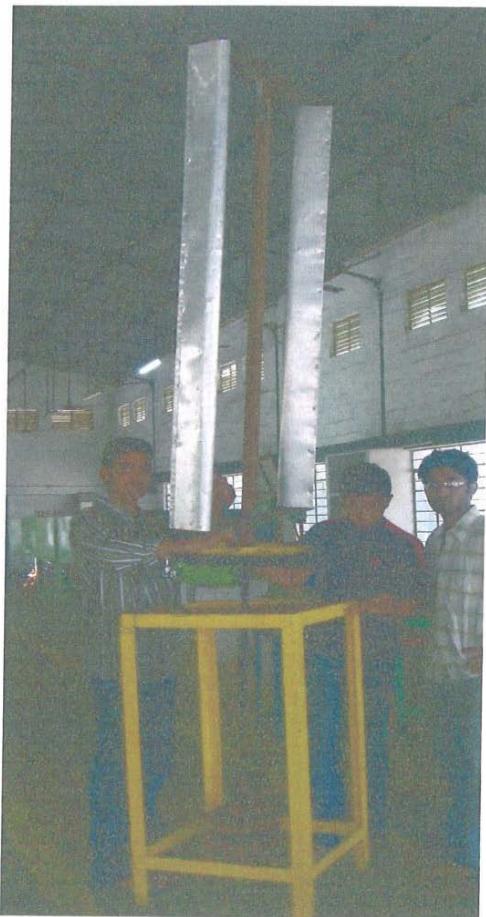
Bigger Rotors: Darrieus (170cm x 100cm) with wooden core with FRP skin symmetric airfoil blades and Giromill (170 cm x 86cm) with symmetric airfoil blades of mild sheet, were fabricated. Both are cantilever supported, with pivot bearing and sleeve type rotors. The sleeve acts as the torque-tube and the blades are attached directly to it. Bicycle dynamo was to be the token load on the rotor. Photos in page 55 and page 56 of the guided project [5] show both the rotors, the square shaped pedestal structure of steel, dynamo, the gear wheel, and the fan blower in the far behind. Fulcrum round bar is positioned snugly and diagonally on to the square top of the pedestal structure. When the spinning rotor tended to tilt due to the wind thrust, as a gyroscopic reaction, the fulcrum-bar was thumping down one end and lifting up the other end alternatively. Flip-flopping the heavy rotor as if tossing a doll, was a wonderful phenomenon to watch and consolidate the learning of gyroscope in practical application. It reminded rotors for high wind up to $50\mathrm{m / s}$ [4] and their complex dynamics.
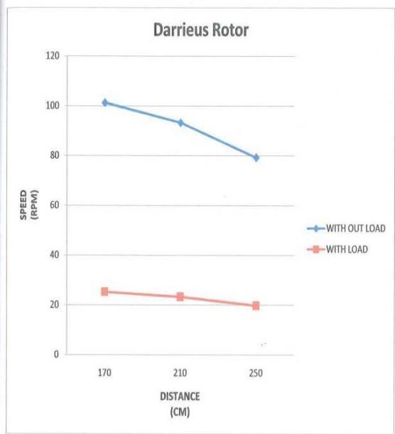
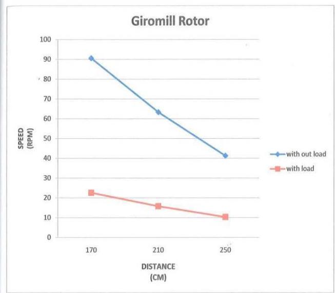
Graphs in page 44 and page 45 of the guided project [5] indicate the rotor(s) spin rate for three flow potentials with and without load. Darrieus rotor being bigger, both by size and inertia, its no-load steady state spin rate shows greater values of 100 to 80 rpm, whereas the Giromill shows values of 90 to 40 rpm.
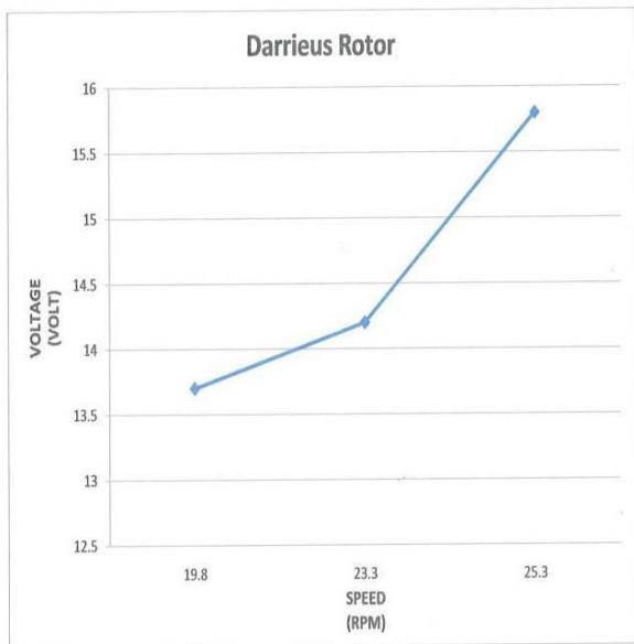
Upon applying the load, spin rates of both rotors precipitously decline to nearly one fourth of their no-load values. During operation, both the rotors maintained upright position; with the axle oscillating cone angle was about 15 degrees. Graphs in page 47 and page 49 of the report [5] show the output voltage as the quality marker of the rotor performance; (that of the future turbine-to-be) which was satisfactory with about 12 to 16 volt.
### c) Tilt & Swivel Darrigenous Rotor's Performance
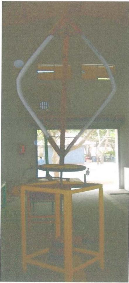
Figure 5/pp 10 of the guided project [6] shows the tilt plus swivel type vertical axis rotor set-up as a precursor to the new wind turbine. The fan blower, positioned in the far behind is visible. This medium sized, modified, Darrieus type is (67cm x 40cm) of two-bladed wooden rotor and with its steel vertical shaft weighing about 8 kg. It is kept up right by the counterbalanced dead weights of 20 kg, positioned below the fulcrum shaft. Figure 7/pp13 shows the details of swivel-base with circular-rail, and the guided support wheels of the fulcrum shaft. The rotor's token loading using the bicycle dynamo is also indicated. A brightly glowing 16 volt DC bulb is the indicator of performance. One crucial change is, the vertical axle has been changed to rotating shaft and fitted with two ball bearings to improve the spin rate of rotor. The top-end of the rotor continues with the pivot bearing, but the lower end in integrally fixed to the shalt by a base clamp plate.
The rotor is experimented for three flow potentials. Maximum r.p.m of 250 was reached on no-load. The data are presented as: (i) performance with load (ii) automatic tilt of axis in degrees (iii) swivel duration taken by the rotor for aligning with the changing wind direction. These have been shown respectively in graphs: (i) Figure 19/pp 32, (ii) Fig.21/pp 34 and (iii) Fig. 23/pp 36 of the guided project [6]. Despite the two-bladed, modified Darrieus rotor being used here for the simplification purpose, full scale design analysis for the prototype may favor a three-bladed rotor, also the one with troposkein shape. Upon pursuing, the geometrical solution of this dissipative nonlinear dynamical system would be a fascinating fractal composition in the phase-space with strange attractors amidst chaotic motions/ trajectories.
## i. Instructive Scaffold to the Prototype
This rudimentary experimental study, consisting of six primitive rotors, lasting for about sixty hours render certain qualitative insights about the tilt and swivel type vertical axis wind turbine, to harness high velocity winds, say up to $50\mathrm{m / s}$ [4].
Next is to go in for the prototype of the first generation: a virtual one leading to the optimally physical one, with the required design-life. Beyond the cut-out wind speed, the rotor's tilt angle may be large enough/say $40^{\circ}$ causing the blade's stall condition, leading to zero power output. Then the rotor either spins idly or by applying brakes, it just becomes a drag chute with zero spin. These options being configuration specific, have to be assessed using the virtual prototype with numerical modeling [7]. Probably, the results may favor a three-bladed Darrieus type rotor with its troposkein geometry, both from the structural and aerodynamic considerations. Avoidance of self-oscillation might be a crucial criterion for the overall stability aspects and control system for safe operation!
The cantilevered-sleeve type rotor, with the sleeve acting as a torque tube seems highly worthy of incorporating. Torque tube could be roomy enough to accommodate large bending deflection of the cantilever axle. The tilt plus swivel axle-turnnion-frame shall have the stability to maneuver the spin & whirl of the rotor and endure the fatigue load due to the turbulent wind. If needed, maximum tilt angle shall be constrained by tying the axle's lower tip, with a leash chain of fixed length anchored to the ground/zero point. The counter weight's bulk and leverage manipulation is one crucial aspect of the overall control system with feedback; its full potential may pave the way for the smoother and safe continuous turbine operation, as a dynamical navigation.
Mass and rotational inertia of the rotor, counter weight, fulcrum point of the vertical axis, maximum allowable tilt angle, elbow room for counter weight movement, within the pedestal structure, swivel bearing base circle diameter, its height from the ground level, and all such parameters are to be delicately balanced in the wind flow, to produce this turbine as a dynamic entity. Frustum of the cone-like shell frame is suitable for the pedestal support structure. The present swivel base may require a top retainer rail additionally and make a cage-type bearing. This helps to tackle gyroscopic reaction couples and extreme severe lift up the rotor, in the stormy and gusty winds up to $50~\mathrm{m / s}$; as if to pluck away the rotor!
As for safety, at the worst blades may buckle or break but never a towering inferno is waiting in the wing, as in the case of HAWT. Any newly designed turbine has to undergo meticulous laboratory and extensive field trials & fine tunings for its assessment. Taming this seemingly chaotic "spinning-top-alike" to deliver a regulated performance is both challenging and beautiful! Hence, these strategic observables, gleaned from the rudimentary experiments seem to render an instructive scaffold for realizing the successful prototype.
The artistic impression of this new version of turbine shown in the last page, kinematically resembles to fit in between the Lagrange-top and Kovalveskayatop. This is just a coincidence and even if it is a pareidolia, to be in their rank is truly the windfall. May this device be blessed to identify its singularities and steer clear toward success.
## III. CONCLUSION
Harnessing through high winds up to large cutout wind speed, with major safety and minimal maintenance, is the hallmark of the new Tilt & Swivel type vertical axis wind turbine T&S (VAWT). It is expected that loss of efficiency due to its tilting can be more than compensated by its prolonged working duration in high winds up to $50~\mathrm{m / s}$. Beyond the cut out speed for safety, the rotor can degenerate into a drag chute in the flow field, either with spin or no spin. At the worst, the blades may break or buckle, but can never cause self-destruction of the whole power plant, which is a strong plus point of this design.
Also, the Darrieus type three-bladed rotor with its troposkein geometry results in a light and strong shell structure, to freely spin, toss, and harness the high speed turbulent wind. For the offshore installation as mentioned earlier, the buoyancy and fluid damping effects have to be considered appropriately, with floating base option. This report is about qualitatively suggesting a pertinent design evolved experimentally, for a new turbine meant for high energy wind field. As touched upon in the introduction, there is no qualm in repeating that, this new device is visualized to perform more as a tossing and turning daffodil in the breeze, yet a flexible and tenacious prime mover generating power!
Note on Author's Name
Githaguru and Geethaguru both refer to the same author; phonetic identity triggers the variant spelling.
1. "Nonlinear dynamics of wind turbine wings" (Danish off shore Wind Farms: 5MW Turbines). A technical Report by Jesper Winther Larsen about 163 page report, vol 132/011021-1. Feb, (2005).
2. "Study on Tilt Rotors" - technical article by Dr.
V. Githaguru, Prof. Dept. of Mech. Engg. Present News Letter (2008) by Dept. of Library, B.S.A Present Engg. College, Anna University Chennai, TamilNadu, India.
3. "Experimental Study on Tilt Rotors as New Wind Turbine Models"-Under graduate guided project (2009) by V. Githaguru Dept. of Mechanical Engg. Present Engg College.
4. "Field operations and Track Tests of 1KW small wind turbine under high wind conditions"- upto 50 m/s Hikaran Mastsumiya et.al Journal of Solar Energy Engineering ASME(2010).
5. "Vertical Axis wind Turbine as a free rotor"-Under Graduate guided project (2010) by V. Githaguru Dept. of Mech. Engg, Present Engg. College.
6. "Development of Transmission Gear for tilt Rotor wind Turbine"- U.G. guided project (2013) V.
- Githaguru Dept. of Mech. Engg. Present Engg. College.
7. "Comparative CFD Analysis of Vertical Axis wind Turbine in upright and tilted configuration"-Abdullah mobin et.al Journal of Renewable Energy, Vol.85, Jan(2016) pp 327-337.

- 2.3 TYPs OF ROTORS USED:
- 2.3.1 GIROMILL:
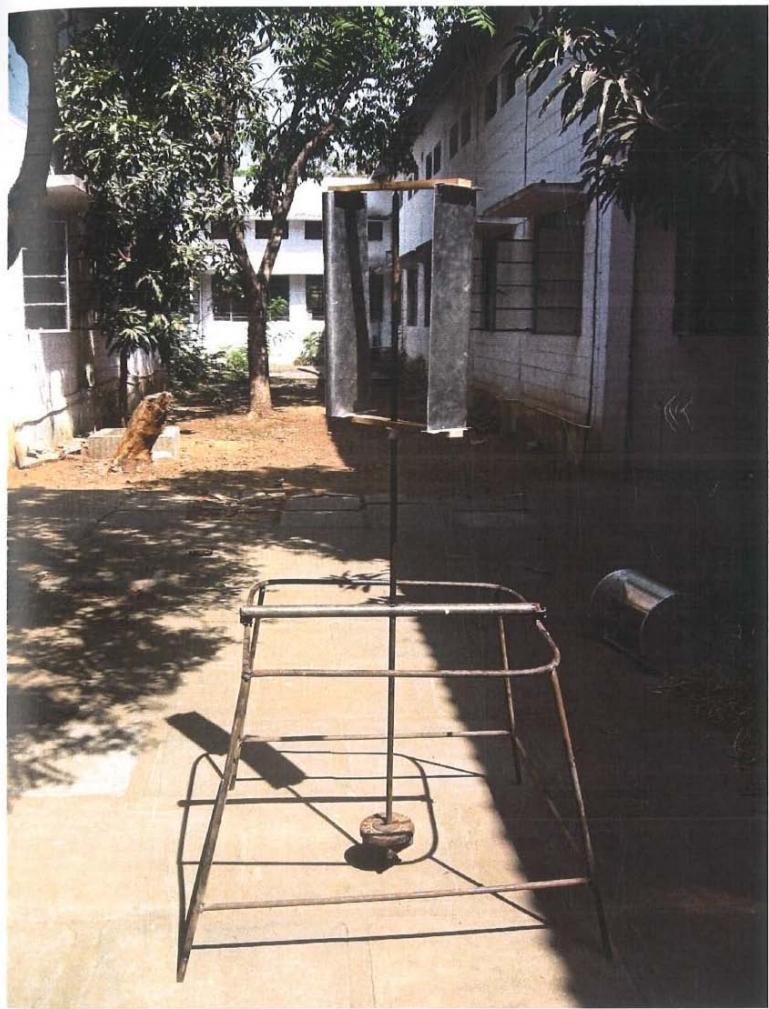
Figure 2.5: Experimental Setup With Giromill Rotor

### 3.2 SAVONIUS ROTOR:
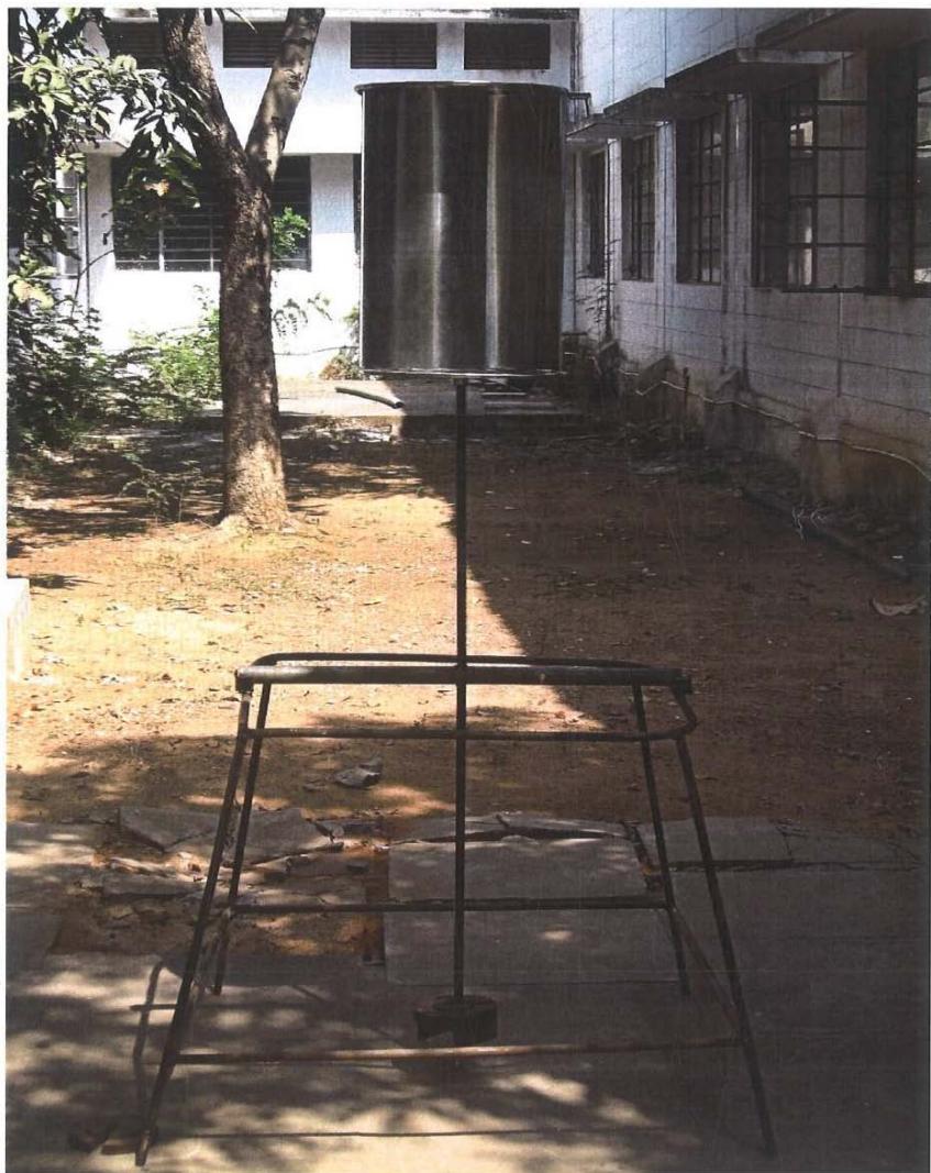
Figure 2.7: Experimental Setup With Savonius Rotor
#### 3.3 SIMPLIFIED DARRIEUS ROTOR:
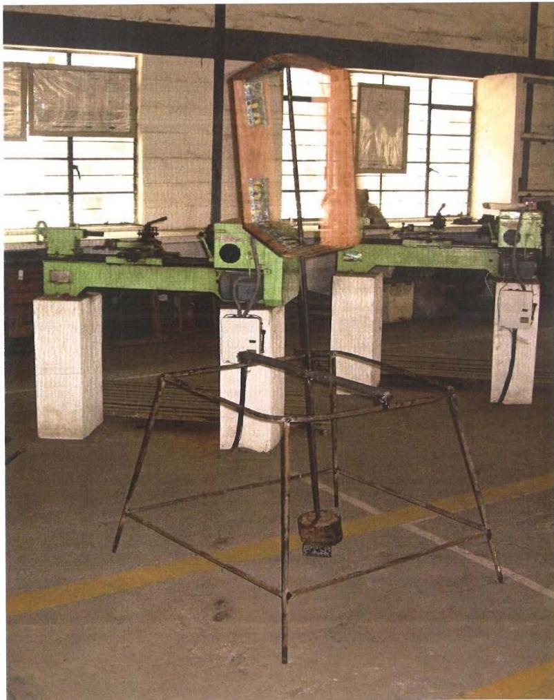
Figure 2.9: Experimental Setup With Simplified Darrieus Rotor

#### 2.3.3.1 SIMPLIFIED DARRIEUS ROTOR'S DIMENSIONS:
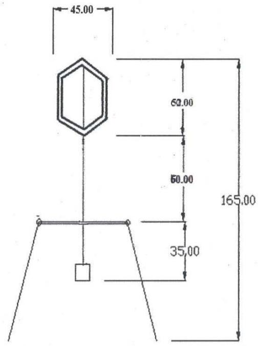
Figure 2.10: Rotor Dimensions (Simplified Darrieus)
ALL DIMENSIONS ARE IN cm
#### POSITION 2:
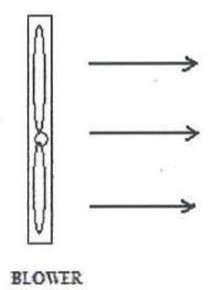
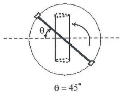
Figure 2.27: Position 2 Setup (Simplified Darrieus Rotor)
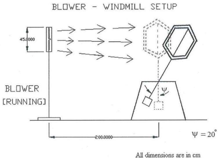
Figure 2.28: Angle Of Tilt For Position 2 Setup (Simplified Darrieus Rotor)
#### 4.2 $\Psi$ Vs $\theta$:
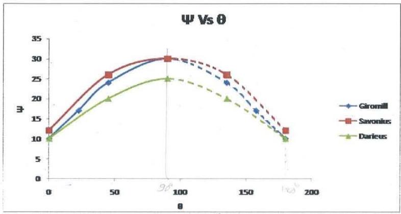
Figure 4.2: $\Psi$ Vs $\theta$
#### 4.3 $\Psi$ Vs TSR $(\lambda)$:
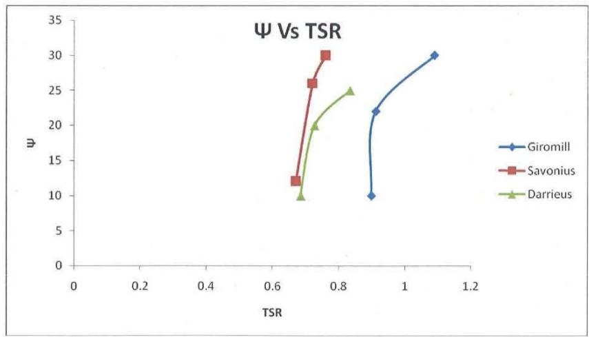
Figure 4.3: $\Psi$ Vs TSR ( $\lambda$ )
#### 11.1. DARRIEUS ROTOR


#### 11.2. GIROMILL ROTOR
8.3.GRAPH:DARRIEUS ROTOR
X AXIS - DISTANCE (CM)
YAXIS-SPEED(RPM)
8.4.GRAPH:GIROMILL
X AXIS - DISTANCE (CM)
YAXIS -SPEED (RPM)
#### 8.5.2. GRAPH: SPEED VS VOLTAGE
X AXIS-SPEED(RPM)
Y AXIS-VOLTAGE (VOLTS)
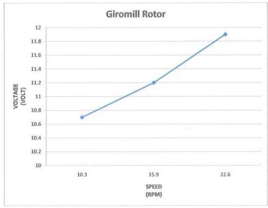
8.5.4.GRAPH: SPEEDED VS VOLTGE
XAXIS-SPEED(RPM)
YAXIS-VOLTAGE(VOLT)
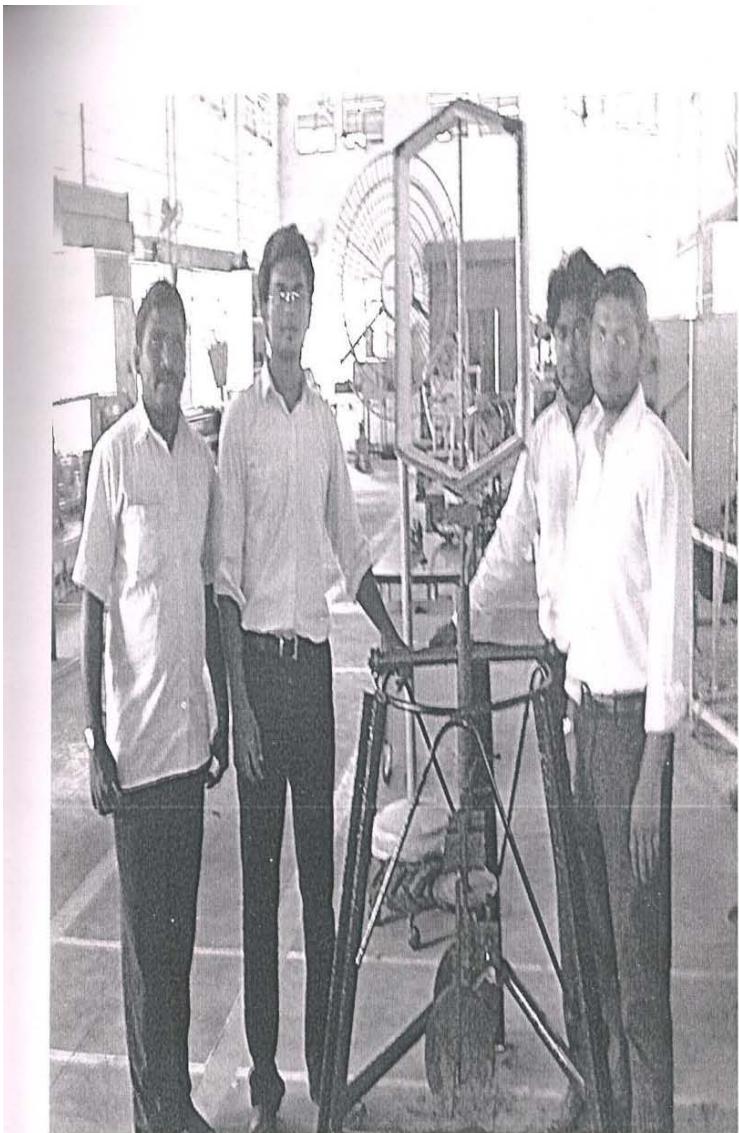
Figure 5: Tilt rotor


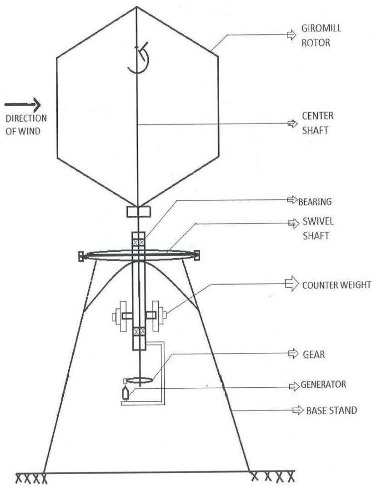
Figure 7: Parts of the tilt rotor
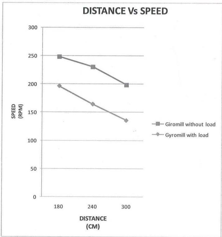 Figure 19: Graph of distance vs speed (with and without load)
X axis - DISTANCE (CM)
Y axis - SPEED (RPM)
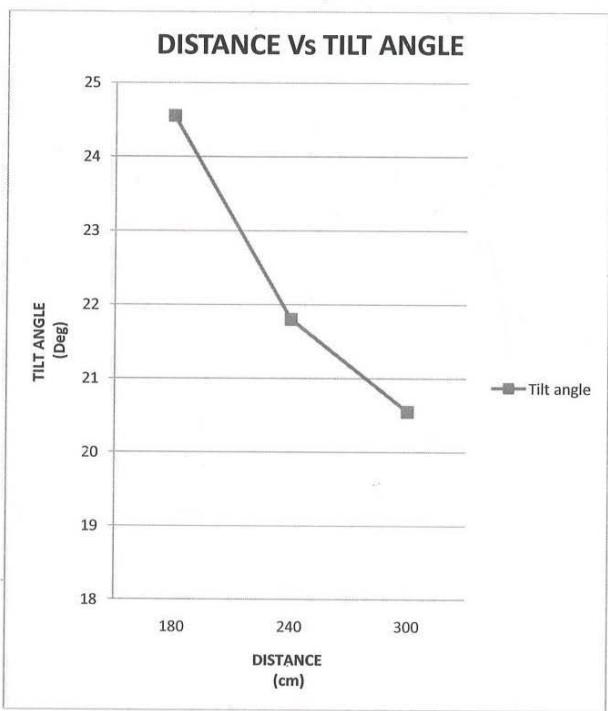 Figure 21: Graph of distance vs tilt angle
X axis - DISTANCE (CM)
Y axis - TILT ANGLE (Degree)
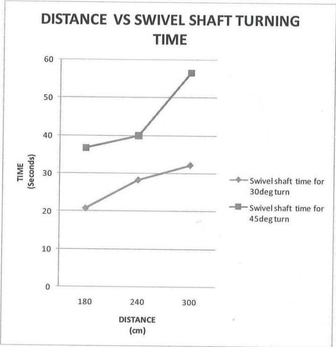 Figure 23: Graph of distance vs swivel shaft turning time
X axis - DISTANCE (CM)
Y axis - TIME (Seconds)
Generating HTML Viewer...
References
7 Cites in Article
O Ljungstrom (2005). New concepts in vertical axis wind turbines /VAWT/ and applications to large multi-MW size, off-shore wind turbine systems.
Boopathy R. (2008). Detecting Phishing Web Sites by a Content-Based Approach CANTINA.
(2009). Experimental Study on Tilt Rotors as New Wind Turbine Models"-Under graduate guided project.
Hikaru Matsumiya,Ryosuke Ito,Masafumi Kawakami,Daisuke Matsushita,Makoto Iida,Chuichi Arakawa (2010). Field Operation and Track Tests of 1-kW Small Wind Turbine Under High Wind Conditions.
(2010). Vertical Axis wind Turbine as a free rotor"-Under Graduate guided project.
Dr. Dhurvey,Dr. Chandrakar,Dr. Ashtankar,Dr. Rothe (2013). RBFN Based IPFC for Enhancement of Power System Security.
Abdullah Chowdhury,Hiromichi Akimoto,Yutaka Hara (2016). Comparative CFD analysis of Vertical Axis Wind Turbine in upright and tilted configuration.
No ethics committee approval was required for this article type.
Data Availability
Not applicable for this article.
How to Cite This Article
V. Githaguru. 2026. \u201cTilt and Swivel Vertical Axis Wind Turbine for High Speed Regions on or Off Shore. Model Rotor(s) Experiments Lead as Instructive Scaffold to the Prototype\u201d. Global Journal of Research in Engineering - A : Mechanical & Mechanics GJRE-A Volume 23 (GJRE Volume 23 Issue A2): .
Explore published articles in an immersive Augmented Reality environment. Our platform converts research papers into interactive 3D books, allowing readers to view and interact with content using AR and VR compatible devices.
Your published article is automatically converted into a realistic 3D book. Flip through pages and read research papers in a more engaging and interactive format.
To harness high velocity and fluctuating wind, this new tilt & swivel type vertical axis rotor, as an original idea is investigated. If the conventional anchoring of its top end with guy wires to the ground is simply done away with, the rotor axle becomes a cantilever; requires it to be more rigid, strong and hence heavy. Instead, the lower end of the axle is modified with fulcrum and the rotor is kept upright with the counterweights. Hence the whole balanced assembly of rotor and generator located on opposite ends, can easily tilt about the turnnion, in tune with the wind speed. Counter weight to the rotor can include additional dead weights, along with the generator and gear train. By automatic tilting, the rotor can work through and up to higher cut-out wind speed. Change of wind direction causes the axle to swivel and align for the continued smooth rotor operation. Hence both the tilt and swivel freedom of the vertical axle/axis, renders a complete new design of the wind turbine for high speed regions up to 50 m/s.
Our website is actively being updated, and changes may occur frequently. Please clear your browser cache if needed. For feedback or error reporting, please email [email protected]
Thank you for connecting with us. We will respond to you shortly.
Lorem ipsum dolor sit amet, consectetur adipiscing elit. Ut elit tellus, luctus nec ullamcorper mattis, pulvinar dapibus leo.
Tilt and Swivel Vertical Axis Wind Turbine for High Speed Regions on or Off Shore. Model Rotor(s) Experiments Lead as Instructive Scaffold to the Prototype